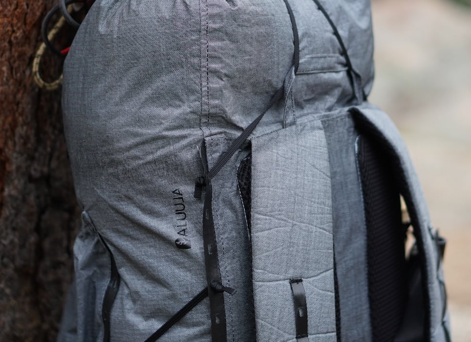
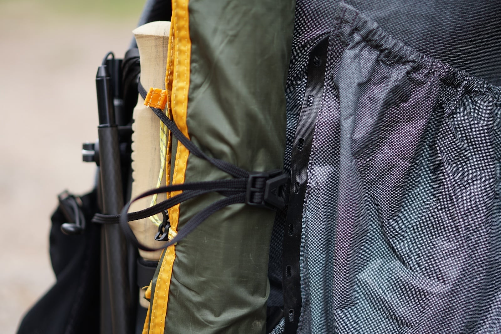
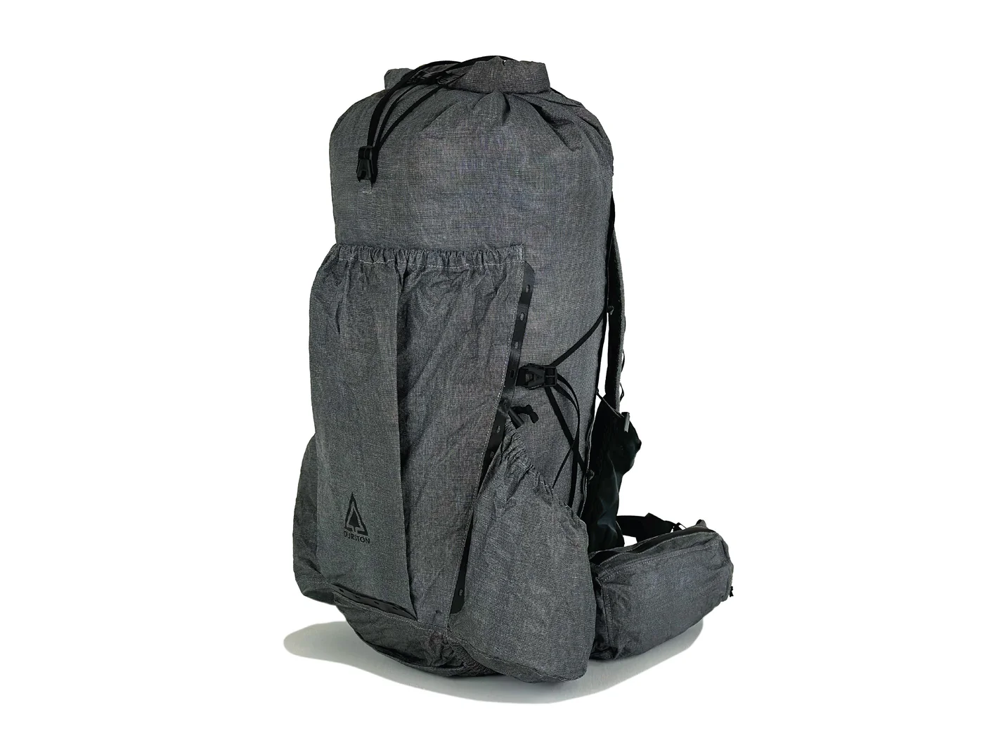
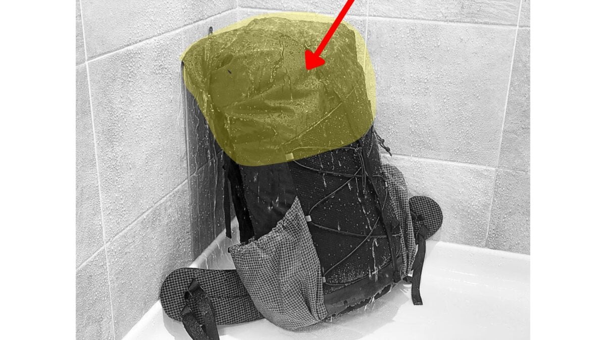
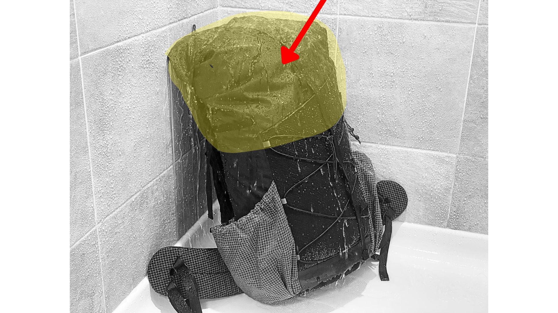
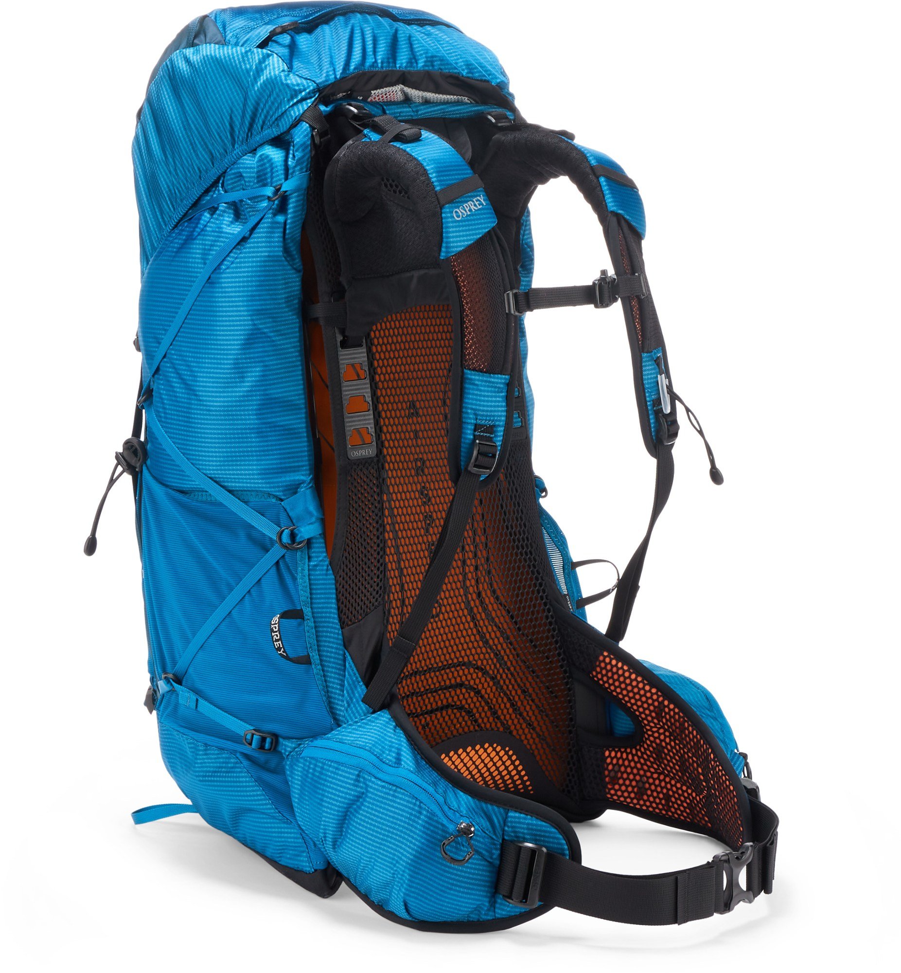
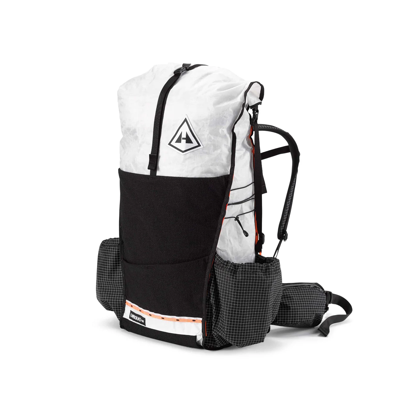
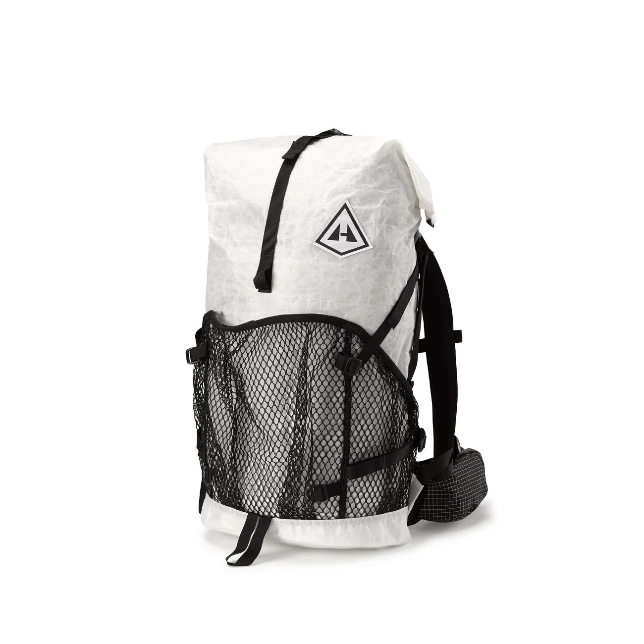
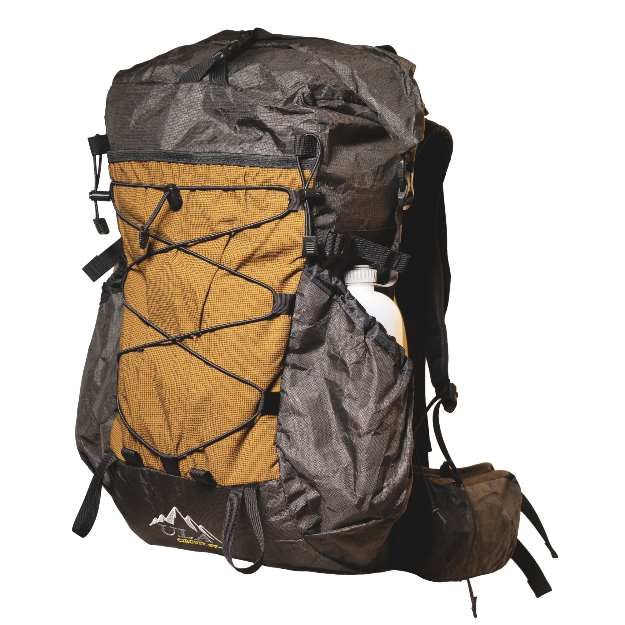
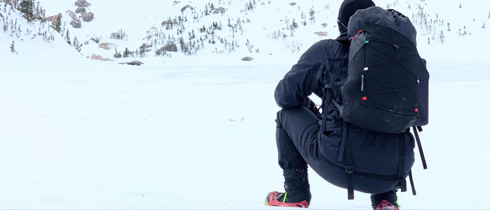
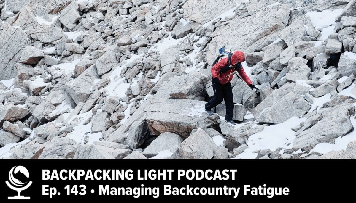
This is Part 1 (of 4) in a new series called Principles of Outdoor Gear Design and focuses on the topic of outdoor gear durability. Ryan Jordan examines durability through the relationship between product, use case, and user behavior. Backpack examples connect materials, manufacturing, and engineering to wear, damage, repair, and continued function. Learn how to interpret durability claims and evaluate the weight, cost, and maintenance tradeoffs involved in choosing gear. (This series is made possible by support from Vaer Watches as part of the Built by Vaer initiative, a partnership collaboration between Backpacking Light and Vaer to bring in-depth educational resources about product design to the Backpacking Light community.)
Show Notes
What do we mean by durability – and what do we value?
Surviving a difficult trip, remaining functional for years, and retaining a nearly new appearance describe different outcomes.
Product × use case × user behavior: construction gives gear physical capabilities; environmental exposure, trip demands, and handling influence how long it remains useful.
Our expectations determine how much deterioration, maintenance, and repair we accept. Those judgments are distinct from the physical changes in the gear.
Years of ownership need context: amount of use, loads, conditions, handling, and repair history.
How is durability engineered?
Finished-product behavior depends on materials, geometry, connections, and manufacturing quality – not the main fabric alone.
Abrasion, puncture, and tearing involve different processes. Evidence from one test does not answer every question about field damage.
Shoulder-strap attachments illustrate how stitches, fabric, and reinforcement transfer loads, and why stronger thread alone may not solve a seam failure.
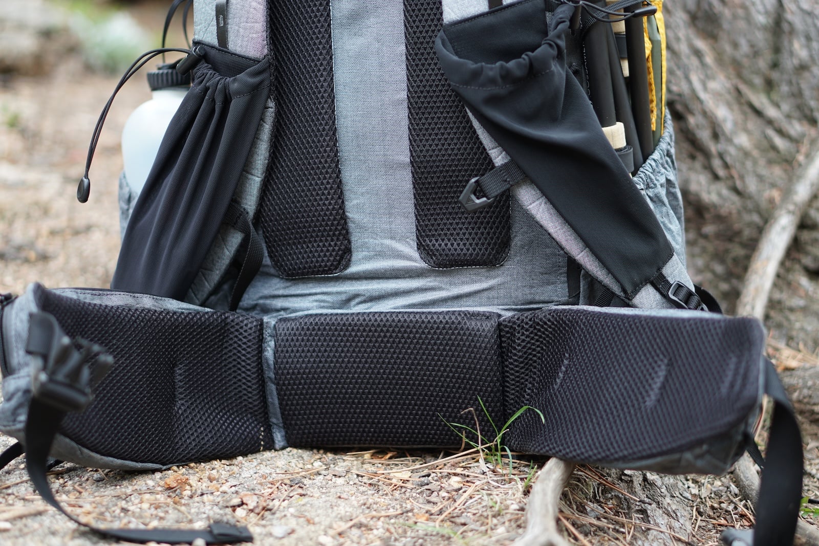
Frame sleeves and suspension connections show why an intact frame can lose useful support when surrounding components deteriorate.
Strength, stiffness, toughness, fracture toughness, fatigue resistance, and creep resistance describe different responses to loads and damage.
Environmental exposure, hardware slippage, damage tolerance, repairability, and design margin also affect continued function.
Additional weight or cost helps only when it addresses the construction or failure mechanism limiting useful life.
How do use case and user behavior affect durability?
Thru-hiking adds repeated loading and prolonged exposure, with loads changing between resupplies.
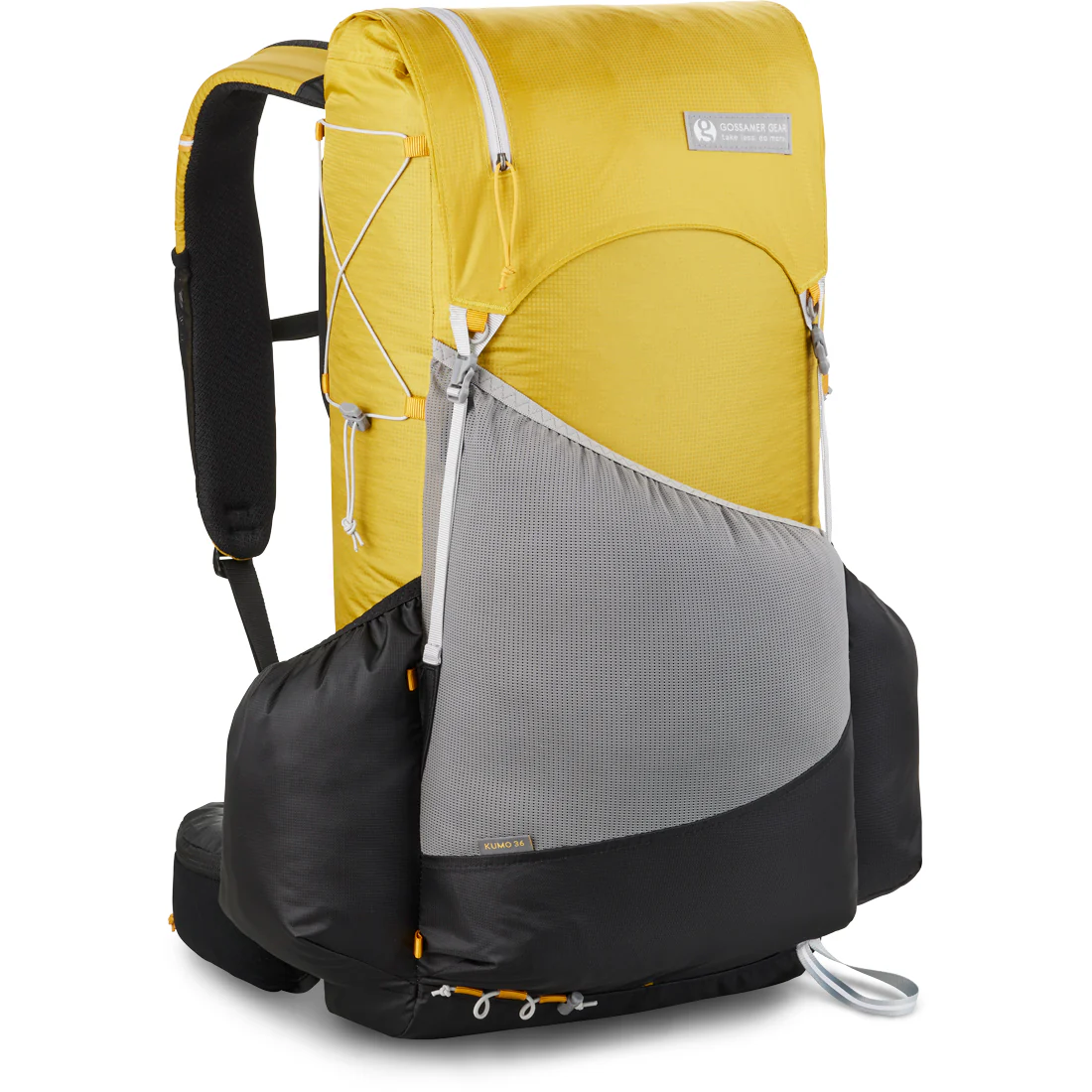
Brush can snag exposed pockets and their attachments; how the pocket is packed and how the user frees a snag change the demand.
Sandstone scrambling exposes fabric to abrasion and may require lifting the pack through different attachment points.
Heavy carries place demands on the frame, sleeves, seams, and suspension connections together.
Setting down, dropping, lifting, sitting on, inspecting, and repairing gear influence the forces and damage it experiences.
Considering user behavior does not excuse poor design or manufacturing. Evidence is needed before assigning a cause to a failure.
How do we apply this when choosing and using gear?
Interpret positive and negative durability reports against the use and handling behind the reported outcome.
Identify the function and component that need to last under your conditions before accepting more weight or paying more.
Include the skill, time, and willingness required for maintenance and repair in the buying decision.
Recognize that continued function through repair and preservation of original parts reflect different expectations of endurance.
These resources support the general concepts discussed. They do not establish the remaining service life of a particular product or the cause of an individual failure. ASTM links provide standard descriptions; full procedures may require purchase.
Principles of Outdoor Gear Design is a four-part series created in partnership with Vaer Watches that features episodes about durability, usability, simplicity, and performance in outdoor gear design. It combines philosophy, engineering, and practical backcountry experience for outdoor industry professionals and users.
A technical comparison of modern fabrics used in backpacks, shelters, and storage systems, including DCF, Ultra, X-Pac, ECOPAK, silnylon, silpoly, and ALUULA. The tables compare weight, tear strength, abrasion resistance, waterproofness, dimensional stability, construction, and key tradeoffs using current manufacturer data.
Technical fabrics are often classified by material family, including DCF, Ultra, X-Pac, ECOPAK, silpoly, and silnylon. That level of classification is useful, but it is not sufficient for material selection for specific product use cases. Individual constructions within the same family can differ substantially in mass, tear strength, abrasion resistance, waterproofness, dimensional stability, and construction method.
The tables below separate three major applications: packs, shelters, and storage systems. Each application imposes a different set of mechanical and environmental demands.
How to Read These Tables
Published test values are only directly comparable when the test methods are sufficiently similar. Tear, puncture, abrasion, and waterproofness results can vary with specimen geometry, test standard, loading method, and manufacturer protocol.
Where manufacturers publish compatible test data, the values provide useful comparative information. Where they do not, the table reports the available specification without implying equivalence. Where no useful value is published, the table states Not published.
Values produced using different test methods or manufacturer protocols should not be treated as directly equivalent.
Fabric Families and Construction Types
The materials in these tables use several different construction strategies. Understanding those constructions helps explain differences in weight, stiffness, tear resistance, abrasion resistance, waterproofness, and manufacturing requirements.
Dyneema Composite Fabric (DCF)
Dyneema Composite Fabric uses nonwoven Dyneema fibers arranged primarily in 0-degree and 90-degree orientations and bonded between thin film layers. The resulting laminate has very low stretch, low water absorption, high tensile strength for its mass, and high waterproofness. Lighter constructions are commonly used in shelters and ultralight storage products, where low mass and dimensional stability are priorities. Their principal limitations include relatively low puncture resistance in the lightest constructions and an exposed film surface that provides less abrasion protection than a woven-faced composite.
DCF Hybrid constructions add a woven face fabric to the composite structure. The face improves abrasion resistance and handling durability while increasing mass. Dyneema also now produces woven composite constructions in which a woven Dyneema face is bonded to the composite core.
Challenge UltraWeave
UltraWeave is a woven composite developed primarily for packs and other high-load applications. The face combines UHMWPE, marketed by Challenge as Ultra-PE, with high-tenacity polyester and is laminated to a waterproof film. Current UltraX constructions also use Ultra-PE CrossPly reinforcement.
UltraWeave differs fundamentally from DCF. Its woven face carries structural loads and provides substantial abrasion resistance, while the film provides waterproofness and dimensional support. Ultra100X, Ultra200X, Ultra400X, and heavier versions primarily differ in face-fabric denier, mass, and mechanical durability.
UltraWeave specifications are from Challenge Outdoor’s current UltraWeave Collection page; legacy/alternate Challenge pages may show different nominal weights.
Challenge UltraTNT
UltraTNT is an ultralight film laminate intended primarily for tents, tarps, and other low-mass structures. It uses polyester film layers reinforced with UHMWPE yarns rather than a conventional woven face fabric. This produces a light, dimensionally stable, waterproof material, but with different abrasion, puncture, and construction characteristics than UltraWeave.
Challenge ECOPAK
ECOPAK is a family of laminated pack fabrics that combines woven face fabrics with reinforcement and waterproof backing structures. EPX constructions use a woven face, reinforcement structure, waterproof film, and woven backing. EPLX constructions remove some structural layers to reduce mass and bulk. These materials represent a more conventional sewn-laminate architecture than UltraWeave and generally provide predictable stitch support and handling characteristics.
Challenge TX Ultra
TX Ultra constructions combine lightweight woven or composite reinforcement with a laminated structure intended for lower-mass applications such as pack liners, accessory bags, and storage systems. They occupy a design space between very light film composites and heavier structural pack laminates.
X-Pac
X-Pac is a family of laminated technical fabrics derived from sailcloth manufacturing methods. The family includes several distinct constructions rather than one material type.
X3 fabrics generally combine a woven face fabric, X-PLY reinforcement, and a polyester film backing. X4 constructions add a woven backing layer. LiteSkin, or LS, fabrics use a nonwoven polyester exterior face with a UV-resistant coating, waterproof film, and woven backing. The LS series is designed to provide high surface abrasion resistance with a different exterior structure than conventional woven-face X-Pac.
X-Pac hyperTEC uses high-modulus fibers for lower stretch and higher strength-to-weight performance. Current UX constructions use a 100 percent Ultra-PE woven face with Ultra-PE X-PLY reinforcement. These fabrics should be considered separately from conventional nylon-faced X-Pac constructions because their fiber system and mechanical behavior are substantially different.
Silnylon
Silnylon is woven nylon fabric impregnated or coated with silicone. It remains widely used in shelters because it provides low mass, good tear resistance, flexibility, and reliable waterproofing. Nylon absorbs more moisture than polyester and can elongate under wet conditions, which may reduce shelter tension during prolonged rain.
Silpoly
Silpoly uses woven polyester rather than nylon as the structural fabric, typically with silicone-based waterproof coatings. Polyester absorbs less water and generally changes dimensions less when wet. This can improve pitch stability in shelters. Mechanical properties vary substantially with yarn size, weave, coating formulation, and finished fabric weight, so silpoly should not be treated as a single standardized material.
ALUULA Composites
ALUULA produces thermoplastic composite fabrics that use high-strength fiber reinforcement bonded to polymer films without conventional adhesive lamination. Graflyte is oriented toward high-strength, abrasion-resistant technical products, while Aeris X is designed for lightweight tensioned structures such as shelters.
These materials differ from conventional sewn laminates because some constructions can be thermally bonded or welded. This can change seam design, reinforcement methods, and waterproof construction. Public comparative mechanical data remain less complete than for several longer-established fabric families, so direct quantitative ranking should be made cautiously.
Pack Fabrics
Pack fabrics must resist sustained loads, concentrated stitching loads, abrasion, puncture, and repeated flexing. Material selection therefore requires more than a comparison of nominal strength.
The primary variables are mass, tear strength, abrasion resistance, stitch support, structural stability, waterproofness, and long-term laminate durability. These properties are not necessarily correlated. A lighter fabric may provide exceptional tear strength while offering less surface abrasion resistance. A heavier laminate may provide better stitch support and surface durability at a substantial mass penalty.
Differences within a single material family can also be large. X-Pac constructions, for example, vary substantially in face fabric, reinforcement structure, backing, weight, abrasion resistance, and tear strength. Ultra constructions likewise span different weights and durability levels.
From a design perspective, the optimum pack fabric is not necessarily the strongest. Which construction provides the required combination of strength, abrasion resistance, sewing performance, durability, and mass for the intended part of the pack must be considered.
Material Technology Comparison - Backpack Fabrics
Material
Weight
Construction
Tear strength*
Abrasion
Waterproofness
Construction notes
Best use
Primary limitation
ROBIC — 210D ROBIC Ripstop Nylon
4.4 oz/yd² (124.7 gsm)
210D ROBIC nylon 6; 3 mm ripstop; UTS backside coating; DWR face
Not published
Not published
Not published
Easy to sew; conventional seam construction.
Conventional pack bodies, pockets, and bags where sewing simplicity matters
Lacks current public quantitative tear/abrasion/HH data for rigorous comparison
X-Pac X4 — VX21
6.2 oz/yd² (210 gsm)
210D nylon face; polyester X-PLY at 22 deg; 0.25 mil polyester film; 50D polyester taffeta backing
24.4/17.2 lb warp/fill; method not stated
500 cycles; ASTM D3884
200 psi; 13.8+ bar
Good stitch support; sew and optionally seam-tape.
General-purpose structured pack bodies
Heavier than newer high-modulus laminates for its tear strength
X-Pac X3 — X21
5.2 oz/yd² (177 gsm)
210D nylon face; polyester X-PLY at 22 deg; 0.5 mil polyester film backing
16/12 lb warp/fill; method not stated
900 cycles; ASTM D3884
200 psi; 13.8+ bar
Reinforce concentrated stitching; sew and optionally seam-tape.
Lighter waterproof pack bodies and panels
Less stitch-supporting backing than VX21
X-Pac LS — LS21
6.3 oz/yd² (214 gsm)
Nonwoven polyester LiteSkin face with UVt coating; 0.5 mil polyester film; 210D nylon backing
9.3/6.3 lb warp/fill; method not stated
2,000 cycles; ASTM D3884
200 psi; 13.8+ bar
Good stitch holding; sew and seam-tape as needed.
High-abrasion pack panels and bags
Low published tear values for weight compared with high-modulus alternatives
X-Pac hyperTEC — UX10
85 gsm
100% Ultra-PE woven face; Ultra-PE X-PLY at 22 deg; polyester film backing
61.8/50.4 lb warp/fill; method not stated
500 cycles; ASTM D3884
200 psi; 13.8+ bar
Reinforce high-load points; sew and seam-tape.
Ultralight high-strength pack panels with reinforced load points
Only 500 abrasion cycles; limited public long-term flex/stitch durability data
Overbuilt for many ultralight applications; cost/stiffness
ALUULA Graflyte — Graflyte V-78
78 gsm
ALUULA Core fused to V-film without glue; 100% PE family architecture per manufacturer
No public quantitative tear method/value located
Not published
Waterproof; quantitative HH/pressure value not published
Heat-weldable; can reduce reliance on stitched seams.
Welded waterproof pack components and experimental pack bodies
Public quantitative tear/abrasion/HH data are insufficient for direct ranking
Published tear and abrasion values are useful screening metrics, but they do not determine pack durability by themselves. Nearly all pack failures I have experienced outside of incidental punctures or mesh tears, the failure is most often localized. Shoulder-strap anchors, hipbelt interfaces, compression points, bottom panels, seam intersections, and repeated fold lines experience much higher stresses than the average panel.
This is why a material with exceptional laboratory tear strength can still require careful reinforcement and load spreading. Conversely, a heavier fabric with more modest “headline” (raw fabric) strength may perform very well if its woven backing, stitch support, and surface durability are better matched to the structure.
For pack design, I generally care less about identifying the strongest fabric than about identifying the lightest construction that preserves adequate margin at the actual failure points.
Shelter Fabrics
Shelter fabrics are governed by a different set of requirements. Important properties include mass, waterproofness, tear resistance, puncture resistance, dimensional stability, wet stretch, UV durability, and seam construction.
Low mass alone is not a sufficient design objective. A shelter fabric must also maintain geometry under sustained tension, resist localized damage, tolerate repeated packing, and retain adequate waterproofness over its service life.
The distinction between silpoly and silnylon illustrates the importance of dimensional behavior. Fabrics of similar weight and waterproofness can respond differently to moisture. Polyester generally absorbs less water and exhibits less wet stretch than nylon, which can reduce shelter sag in wet conditions, but this is not a universal rule that can be applied to all silnylon vs. silpoly comparisons.
DCF occupies a different design space. It provides low mass, low stretch, and high waterproofness, but the lightest constructions provide less puncture and tear margin than heavier versions. Increasing DCF weight can produce a substantial increase in mechanical durability.
Shelter material selection should therefore consider both initial weight and the durability margin required for the expected loading, weather exposure, construction method, and service life.
Material Technology Comparison - Shelter Fabrics
Material
Weight
Construction
Tear strength*
Puncture
Waterproofness
Wet stability
Seam method
Best use
Primary limitation
Silnylon — RBTR 1.1 oz Silnylon
1.24 oz/yd² (42 gsm)
20D x 20D ripstop nylon; silicone/PU impregnated both sides
Not published
Not published
2000 mm H2O; supplier value
More water uptake and wet sag than comparable polyester; no quantitative value published.
Sewn; seam sealing required for waterproof finished article
Conventional lightweight shelters where supple handling matters
Wet stretch/sag and water uptake relative to polyester/composites; lower HH than film laminates
Silpoly — RBTR 1.1 oz Silpoly
1.24 oz/yd² (42 gsm)
20D x 20D ripstop polyester; silicone/PU impregnated both sides
Not published
Not published
2000 mm H2O; supplier value
Lower water uptake and wet sag than silnylon; qualitative supplier claim.
Sewn; seam sealing required for waterproof finished article
Conventional lightweight shelters where low wet sag matters
Lower puncture/abrasion margin than heavier fabrics; HH far below film laminates
Dyneema Composite Fabric — DCF 0.55 (CT1E.08)
0.55 oz/yd² (19 gsm)
Polyester film / 0-90 Dyneema fiber / polyester film
Slit tear: 14 lb, Mil-C-21189
1.8 lb; ASTM F1342 Probe B
15000 mm H2O; AATCC TM127
Very low stretch; low water absorption; resists material sagging per manufacturer
Bond/tape or sew + tape depending design; construction-specific
Minimum-mass bonded/taped shelters
Low puncture margin and exposed-film durability at 19 gsm
Dyneema Composite Fabric — DCF 0.75 (CT2E.08)
0.75 oz/yd² (25 gsm)
Polyester film / 0-90 Dyneema fiber / polyester film
Slit tear: 18 lb, Mil-C-21189
3.1 lb; ASTM F1342 Probe B
20000 mm H2O; AATCC TM127
Very low stretch; low water absorption
Bond/tape or sew + tape depending design
DCF shelters needing more puncture margin
Still puncture- and abrasion-limited relative to woven-faced laminates
UltraTNT — UltraTNT 0.94
0.94 oz/yd²
Ultra-reinforced thin-film shelter laminate
Not published
Not published
200+ psi; manufacturer
Dimensionally stable; does not absorb water per manufacturer
PSA seam/reinforcement tape system; use manufacturer-recommended widths.
Very low-mass taped shelter construction
Manufacturing (cut and sew) precision tooling and process critical
ALUULA Aeris X — Aeris X AX-33
32.9 gsm
100% PE reinforced 0/45/45 X-weave architecture; heat-weldable
Third-party relative strength/tear claims only; no absolute method/value on product page
Not published
Not published
Designed for stretch/tear resistance; low water uptake expected from PE but do not infer numeric behavior
Absolute public test values and field history are limited compared with mature shelter fabrics
I don’t look just at waterproofness or tear strength for shelter fabrics. I’m interested in how the material behaves while continuously tensioned, repeatedly packed, exposed to UV, cycled wet and dry, and loaded by wind.
A very low-stretch laminate can maintain excellent geometry but transfer more load into seams, reinforcements, and attachment points. A woven fabric may deform more, but some of that deformation can distribute transient loads. Neither behavior is inherently superior. The design has to account for it.
Storage-System Fabrics
Storage systems should be evaluated as a separate application class. Stuff sacks, zip bags, pack liners, dry bags, food bags, and organizers experience different loads than either packs or shelters.
These products generally carry lower structural loads than pack bodies, but they are subjected to repeated folding, rolling, compression, closure cycling, localized puncture, and frequent handling. These demands change the relative importance of material properties.
Relevant variables include mass, puncture resistance, flex durability, abrasion resistance, waterproofness, closure compatibility, seam construction, stiffness, and packing characteristics.
Several material strategies are common:
coated woven fabrics that provide flexible handling and conventional sewn construction;
lightweight film composites that minimize mass;
woven-faced composites that improve abrasion and surface durability;
thin tapeable laminates used for liners and ultralight storage products; and
weldable composites used where waterproof construction is a primary requirement.
Closure and seam design are particularly important in storage products. The base fabric may not determine product life. Zippers, roll-top closures, fold lines, seam tape, stitching, and repeated flexing can become the dominant failure points.
Material Technology Comparison - Storage Bag Fabrics
Material
Weight
Construction
Tear strength*
Puncture
Abrasion
Waterproofness
Handling & construction
Best use
Primary limitation
Silpoly — RBTR 1.1 oz Silpoly
1.24 oz/yd² (42 gsm)
20D x 20D ripstop polyester; silicone/PU impregnated both sides
Not published
Not published
Not published
2000 mm H2O; supplier value
Supple and easy to pack; works well with drawcords, zippers, and roll-tops; seam-seal for waterproofing.
Stuff sacks and organizers where suppleness matters more than minimum mass
Lower puncture/abrasion margin than heavier fabrics; HH far below film laminates
ROBIC — 210D ROBIC Ripstop Nylon
4.4 oz/yd² (124.7 gsm)
210D ROBIC nylon 6; 3 mm ripstop; UTS backside coating; DWR face
Not published
Not published
Not published
Not published
Supple, durable, and easy to sew; excellent zipper/drawcord/roll-top compatibility.
Durable stuff sacks, zip bags, and organizers
Lacks current public quantitative tear/abrasion/HH data for rigorous comparison
X-Pac X3 — X21
5.2 oz/yd² (177 gsm)
210D nylon face; polyester X-PLY at 22 deg; 0.5 mil polyester film backing
16/12 lb warp/fill; method not stated
Not published
900 cycles; ASTM D3884
200 psi; 13.8+ bar
Moderately stiff; works with zippers and roll-tops; film side can be seam-taped.
Waterproof zip/roll-top bags with conventional sewing
Less stitch-supporting backing than VX21
ECOPAK EPLX — EPLX200
4.8 oz/yd² (162 gsm)
C0 DWR 200D recycled polyester face; 45 deg Blue CrossPly; 0.5 mil RUV matte film
21.3/24.2 lb warp/fill; ASTM D2261
Not published
500 cycles; ASTM D3884
200 psi; 13.8+ bar
Light film-backed laminate; good for liners, pouches, and roll-tops; PSA tape compatible.
Lightweight pouches, liners, and roll-top bags
Lower stitch-holding than backed EPX; reinforcement required at high-load stitching
Dyneema Composite Fabric — DCF 1.6 (CT5K.18)
1.6 oz/yd² (53 gsm)
Polyester film / 0-90 Dyneema fiber / polyester film
Slit tear: 34 lb, Mil-C-21189
5.2 lb; ASTM F1342 Probe B
Not published
20000 mm H2O; AATCC TM127
Very light and crinkly; well suited to taped/bonded stuff sacks and roll-tops.
Minimum-mass stuff sacks and dry-bag-style storage
No published abrasion-cycle metric; film surface can be damage-sensitive
50D woven polyester face / 0-90 Dyneema fiber / polyester film
Slit tear: 42 lb, Mil-C-21189
7.3 lb; ASTM F1342 Probe B
Not published
20000 mm H2O; AATCC TM127
Woven face improves handling and surface protection; good zipper and roll-top compatibility.
Light woven-faced zip bags and pouches
No standardized abrasion-cycle value published in Fabric Finder
UltraWeave — Ultra100X
3.6 oz/yd² (122 gsm)
100D Ultra-PE/high-tenacity polyester face; Ultra-PE CrossPly; 0.75 mil film backing
69.4/89.6 lb warp/fill; ASTM D2261
Not published
3,600 cycles; ASTM D3884
200 psi; manufacturer
Light and crisp; strong pouch/roll-top candidate; PSA tape compatible.
Ultralight durable pouches and roll-top storage
Film-backed stitch/flex behavior needs construction discipline
UltraWeave — Ultra200X
4.6 oz/yd² (155 gsm)
200D Ultra-PE/high-tenacity polyester face; Ultra-PE CrossPly; 0.75 mil film backing
103.1/133.2 lb warp/fill; ASTM D2261
Not published
4,400 cycles; ASTM D3884
200 psi; manufacturer
Crisp and robust; suited to hard-use pouches and roll-tops; PSA tape compatible.
Robust technical storage and hard-use pouches
Higher cost; film-backed construction requires careful seam/load design
TX Ultra — TX70 Ultra
2.9 oz/yd²
70D recycled polyester ripstop face; 45 deg Ultra CrossPly; 0.25 mil PET film
ASTM D2261: manufacturer reports does not tear (no numeric value)
Not published
500 cycles; ASTM D3884
200 psi; 13.8+ bar
Very light, thin laminate designed for small bags and liners; tapeable seams.
Small bags, pack liners, and accessories
Not intended for concentrated pack loads without reinforcement
UltraTNT — UltraTNT 0.94
0.94 oz/yd²
Ultra-reinforced thin-film shelter laminate;
Not published
Not published
Not published
200+ psi; manufacturer
Extremely light film laminate for bonded/taped sacks; crease durability remains an evidence gap.
Experimental minimum-mass taped sacks or liners where flex/crease durability is acceptable
Current quantitative product specs need a direct manufacturer sheet before publication
ALUULA Graflyte — Graflyte V-78
78 gsm
ALUULA Core fused to V-film without glue; 100% PE family architecture per manufacturer
No public quantitative tear method/value located
Not published
Not published
Waterproof; quantitative HH/pressure value not published
Soft hand with strong welding/bonding potential; attractive for welded waterproof storage.
Welded dry bags, pouches, and waterproof storage
Public quantitative tear/abrasion/HH data are insufficient for direct ranking
In storage products, I’ve learned that the strongest fabric may not produce the longest-lived product. Repeated rolling, folding, zipper cycling, seam-tape flexing, and crease formation can dominate service life. For very light laminates, I would treat flex durability as a first-order design variable rather than an afterthought.
Interpreting the Comparison
Technical fabrics should not be ranked on a single performance axis. Material selection is a multi-variable engineering decision.
A fabric that improves tear strength may increase stiffness or cost. A construction with high abrasion resistance may carry a significant weight penalty. A very light laminate may reduce system mass while providing less puncture tolerance or more demanding seam requirements.
Fiber type also does not determine finished-fabric performance by itself. Face fabric, film structure, reinforcement architecture, coatings, adhesives, backing layers, and seam construction all affect the behavior of the finished material.
The most useful comparison is therefore application-specific. The objective is to identify the construction that provides sufficient strength, durability, waterproofness, dimensional stability, and manufacturability at the lowest appropriate mass for the intended use.
A Practical Material-Selection Framework
I evaluate technical fabrics in this order when I’m shopping for gear or specifying materials for an MYOG project:
Identify the dominant failure modes for the product and the specific panel or component.
Determine the minimum required strength, abrasion, puncture, waterproofness, and dimensional stability.
Evaluate how the material interacts with seams, bonding, reinforcement, and load transfer.
Add durability margin for uncertainty, contamination, aging, field repair, and manufacturing variability.
Only then optimize for weight reduction.
Related
Advances in Materials and Manufacturing in Ultralight Backpacks – A detailed technical assessment of ALUULA Graflyte, DCF, woven UHMWPE laminates, seam construction, fusion bonding, delamination, and the engineering tradeoffs shaping newer ultralight packs.
Market Report – Pack and Shelter Fabrics – Ultra-light backpack and shelter fabrics: Explore materials, performance, and construction. Nylon, polyester, UHMWPE, coatings & more.
An ultralight winter stove is simple in concept—but devilishly complex in execution. This deep dive traces the evolution of a remote inverted-canister stove through eight generations of design, testing, and refinement. The result is a 75-gram V8 vortex stove shaped by careful experimentation with airflow, thermal balance, burner geometry, fuel vaporization, and field-worthy component design.
Introduction
Herewith, my latest remote inverted canister winter stove.
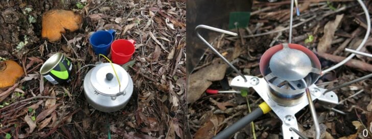
On the left, the V8 stove has disappeared into my Trangia kettle, while on the right, I have removed the kettle so you can see the stove. It weighs 75 g, including a long carbon fibre handle. There is a 76×400 mm titanium foil windscreen around the stove, weighing all of 12.5 g.
But before I tell you the tale of the stove, let me give some background to my stove-designing games.
Table of Contents • Note: if this is a members-only article, some sections may only be available to Premium or Unlimited Members.
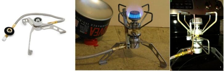
My stove adventures probably started when Brunton sent me their ‘Stove Stand’ for review. This cute device converted a high, wobbly upright canister stove into a more stable and lower one, with the canister off to one side, safely out of the way. Well, that was the idea, anyhow. It worked, and I reviewed it here many years ago.
It was a cute idea, but so limited: the canister still had to sit upright, or liquid fuel would appear on the jet, and you would get an exciting flare-up. I did wonder whether this could be fixed. Perhaps a strip of copper running down from the flames to the metal inlet fitting might carry enough heat for vaporisation? The Alpine Bomb (check the web) does this after all. So I experimented.
On the left, we have the basic Brunton Stove Stand. In the middle, I have put my GST-100 stove on the stove stand and added a copper strip from the flames to the input fitting, to vaporize the incoming liquid fuel. As you can see from the inverted canister behind it, this idea worked fine. I call this stove my V0. After I published this, Christopher Whitter had a go, using heavy copper wire (photo on right), and this too worked fine.
This got me thinking about remote inverted canister stoves for winter trips. To be sure, some commercial units existed at that time, but they were a bit heavy. Some of them were straight-out clumsy. Could I do any better? I would need a stove (or burner), a hose, and a canister connector (plus my wife really did not like the kerosene fumes from my Coleman Peak Apex II stove).
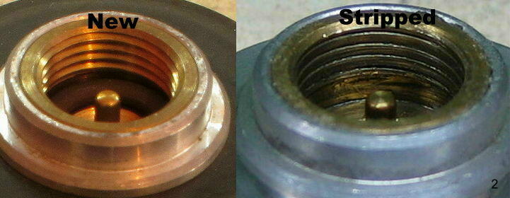
About the same time, my GST-100 stove failed partway through a 2-month-long trip in Europe’s Pyrenees, due to the rough threads on the gas canisters chewing away at the brass thread. This rather annoyed me at the time, and I did not want a repeat of the problem. My canister connector should not screw onto the canister like this.
Obviously, a better canister connector was needed. At the same time, I wanted a design with two valves: one good control valve somewhere near the burner and one fast-acting on/off valve right at the canister for safety. Fairly obviously, the control valve had to be on the gas flow rather than on the liquid flow if I wanted fine control of the flame.
The Original Stove (V1)
You can review my original design process of the stove, catalogued through five installments below:
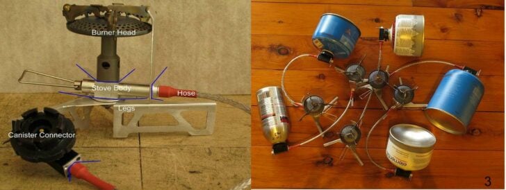
Leaping ahead a bit, I ended up with this (left photo). A stock burner top on a stove body of my own design, sitting on some support legs, a Heat Shunt (unlabeled) from the flames to the stove body, a light hose, and a versatile canister connector. A ‘light hose’ means that the hose should be flexible, unlike many commercial offerings. The connections at each end of the hose should be able to rotate, so the hose could sit flat despite any curls. The photo on the right shows the same connector attached to screw-thread canisters, CampinGaz canisters and the very light Coleman PowerMax canisters. And it does show the curls in the hoses.
The latter two canister designs have connectors which rely on lugs under the rim of the Lindal valve rather than a screw thread on the central spigot, and are in my opinion, far more reliable. Shades of Betamax. In the early days we could only get the CampinGaz canisters when wandering around in Europe, but that is (usually) no longer a problem. Never mind: I wanted the option. In the end I sold about 115 of these stoves around the world. They are V1.
I did not feel like machining 115 of these by hand, relying on every one to be identical. I may be good, but I’m not that good! And for reliability, I wanted all the parts to be interchangeable. So I bought a small CNC machine to do it for me. Programming a CNC is utterly different from writing a program for a conventional computer, so learning how to do that was great fun. Yes, you can get CAD/CAM software to write the programs for you, but at this level of complexity you would be looking at very big dollars – maybe tens of thousands. Not for me.
Vortex Burners: V2 and V3
When designing the second and third versions of my stove, I was thinking about replacing the commercial burner top on the V1 when I got diverted into playing with Vortex Burners. This design is the same as the classic MSR XGK: a chamber with the flame inside and more flames coming out the top. It has no V1-style heat shunt per se; rather heat from the flames inside the burner chamber radiates down onto the base plate and the jet, heating the stove body underneath. (The MSR XGK has a ‘preheat’ fuel line over the top of the stove, in the flames.) A small point: Vortex Burners tend to roar a bit. My wife likes the noise: it means coffee or dinner is coming.
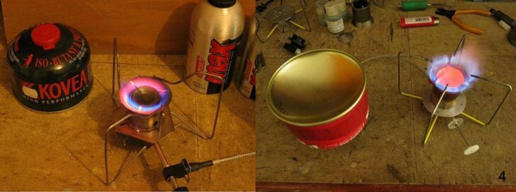
The version on the left was an early one, using titanium and stainless steel, to test the concept. It worked well, but it had two problems: it was heavy, as might be expected given the metals used, and the titanium wire pot supports were unreliable. They look nice, but they rely on ‘spot welding’ titanium wire, and that weld is not really a metal weld. It is just two wires mashed together under heat with the titanium oxide layer still between them. The joint will fail under load.
The version on the right has only the tips of the Ti wires in the flame, to get red hot. This is not only safer, it keeps the CO level right down. The glowing red disk in the middle is the splash plate, and it keeps the flames inside the chamber. Without it there, the fuel would shoot up in the air with dangerous consequences. It led to V2 and V3, which I sold.
V4: Upright Canister Stove
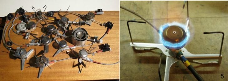
Tidying up everything after the V3, I found a box of incomplete upright burner head designs which I had been playing with but which I had abandoned for the Vortex design. I went back to experiments with an upright burner, and made the V4. It has internal baffles (inside the burner head) to mix and direct the gas. It used a Heat Shunt again. A motley collection is shown here in the left, with V1 stoves at the left and the venerable V0 (used across Switzerland) at the back. Some of the other designs in the photo – well, I was experimenting at the time.
On the right we have the eventual V4 stove design. The design of the burner head worked nicely, but it was a bit complex to make. Several fiddly bits inside the head were needed to get the gas flowing in the right direction (upwards to the pot), while not adding too much weight.
Out of all this I identified a major problem: not in the stove itself, but how to support the stove and the pot. The thing is that one has to be able to pack the stove away into a small volume, and that means the legs have to be able to be folded up a bit. In the left photo some rather nice titanium zigzag legs may be seen (try bottom right). They were nice, but tricky to make and they required rather a lot of sheet Ti. On the other hand, the wire legs on the right proved to be quite strong enough, and much lighter.
Thermal Balance
As part of the V4 design, I had to work out what size heat shunt (taking heat from the flame to the stove body) should be used. Obviously the stove body has to get hot enough to (very) reliably vaporize the incoming liquid fuel so no liquid fuel comes out the jet. After all, you do not want any flaring inside a tent in a storm in the snow. At the same time the stove body must not get too hot or it will damage the Viton O-rings and the PFA tubing. Both of these have an upper temperature limit of about 250 C, or a bit lower (figures from different vendors vary a little bit). I strongly prefer that all temperatures stay below 200 C; I prefer about 120 C.
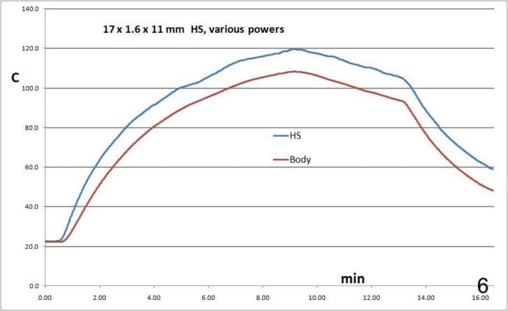
Basically what is needed is a balance. Heat coming down the Heat Shunt from the flames should match the heat required to vaporize the fuel as it enters the stove body. Now, to get this balance in the range from a very low flame to a very high flame is a bit tricky. By this stage I was doing a fair bit of temperature measurement using my marvelous LabJack data logger. The graph here shows what is going on and some of the problems (and the value of real measurements). It does not represent the final V4 stove design of course.
Now, what do the measurements look like?
The blue line labeled ‘HS’ is the temperature near the top of the heat shunt (but not in the flame). The red line labeled ‘Body’ is for the stove body. At the start the fuel feed (at a low power) was gas, not liquid, the stove heated up, and the canister cooled a bit. Around 9 minutes (just an experiment) the canister was inverted and vaporizing the liquid fuel started to take energy from the stove body. The body started to cool down, dragging the splash plate down with it. Yes, they are coupled.
Around 13 minutes the power was turned up a fair bit, more liquid fuel came in, and more energy was sucked out of the stove body. Around 16 minutes the stove body had cooled to just over 40 C in my lab at about +20 C. In the snow the stove would be hovering on flaring. Now I know what is going on, and how to measure it.
Since most of this work is done in my lab at +20 C rather than in the snow at -20C, I needed some way of converting the results from ‘lab’ to ‘snow’. It seemed reasonable to just subtract 40 C from the measurements. This is not perfect of course, but close enough. And remember: the ‘boiling point’ of a 70/30 mix of n-butane and propane is around -24 C. Below that everything gets a bit more tricky, and I go home anyhow.
V5 Design
This was meant to be a simpler burner head to replace the commercial ones in the V4, and to be simpler4, but in the end nothing gelled well enough. Part of the problem was that I lacked the facility for hot forging of sheet titanium (while Asian factories have that). I can form sheet aluminium, but it melts too easily. Pass on.
V6: another Vortex burner
And so I returned to the Vortex Burner concept. It would seem simple since it does not need a Heat Shunt. However, there were some complications I wanted to examine. Obviously the stove body has to get hot enough to (very) reliably vaporize the liquid fuel. You do not want any flaring inside a tent in a snow-storm. So – measurements.
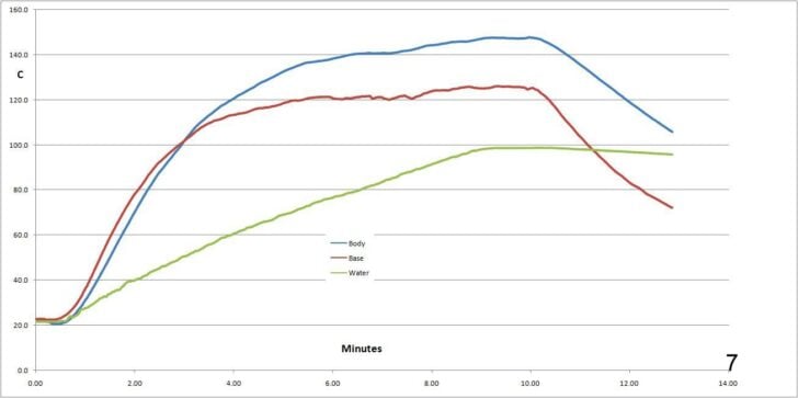
In particular, I was monitoring the temperature of the stove body, where the fuel comes in, and the flat (base) plate between the stove body and the titanium burner chamber. My theory at the time was that the flames heated the base plate, and that the base plate heated the stove body bolted to it. It turned out that there is a bit more to it than this. Anyhow, this graph shows the stove heating a litre of water in my Trangia kettle, but with a twist.
What might appear strange in this graph is that the stove body (blue) seems to have got hotter than the base plate (red). Normally the plate should be 20 – 40 degrees hotter than the stove body. The explanation is simple: the temperature probe for the base plate is a fair distance from the stove body, right out at the edge of a largish base plate, and was subject to air cooling. You do get such cooling when everything is above 100 C! As this shows, understanding what is going on and exactly what is being measured is essential.
The important bit from this graph is that the stove body got just a bit above 120 C and no further. Given that this was measured in my lab, at an ambient of +20 C, it would be reasonable to say that the stove body would still be at +80 C or more when in the snow with an ambient at -20 C. That is, subtract 40 C from everything. Nonetheless, the stove body is far above the boiling point of liquid butane, which is around 0 C. This is ‘satisfactory’.
An important detail which is not apparent from any of this concerns the air flow into the chamber. A small excess amount of air mixing with the fuel is fine: it ensures complete combustion and avoids the release of the deadly carbon monoxide CO. On the other hand a larger excess of incoming air just has to be heated up without contributing anything to the flames. An excess is simply a drag on the flame temperature, reducing the efficiency. Also, the excess air made lighting the stove difficult (explanation later). A balanced amount of air is needed.
The final design of the V6 is shown here. I sold some of them.
V7: SUL
By this stage I thought I had finished designing stoves, but a little demon crept in and got me wondering about SUL. To be sure, commercial remote inverted canister stoves are all heavier, while mine are generally about 90 g. But I wondered: how low could I go? I started to fiddle.
First up, it seemed that a Vortex Stove would not be a candidate for SUL, so I focused on the V1 design: a base with an upright burner. I could see several areas where an upgrade would be possible. A lighter canister connector, a lighter hose, a lighter stove body, and a lighter burner head.
I will briefly mention the hose. Commercial manufacturers don’t want to mess around: they buy high temperature reinforced fuel hose by the reel. This stuff was made for the race car people: it is very ‘robust’ and stiff and abrasion-resistant. Well, fine for race cars, but what has that to do with my little stoves? A bonus maybe is that it is mostly proof against novice users as well. I wanted better. Some PFA tubing with 2.0 mm outside diameter with some custom stainless steel braid was chosen: a bit thinner than the 3.2 mm PFA hose I had used on previous models.
This project ended up as V7, weighing only 45 g complete. It uses a BRS-3000T burner as the lightest available, plus the BRS-3000T has its own pot supports. The design needed a stove support of course, and this needed to be detachable for packing.
I had to use a lot of data logging in designing the Heat Shunt, to get balanced heat flow at OK temps. First of all, in my excessive enthusiasm for weight reduction, I had dispensed with the Heat Exchanger part of the stove body see previous stove articles). That did not work! Then I had to pick the right Al alloy for high thermal conductivity. The common 5005 alloy proved significantly better for this than the 5082 alloy I had been using. Then I had to design the top bit where the flames hit, to get heat into the shunt. What was interesting here was that at low power the flames hit the heat shunt nicely, but at high power the flames could go past the heat shunt – just when more energy was needed to vaporize the increased flow of fuel. This was soon solved: I bent the tip of the heat shunt slightly into the flames. You can see this in the photo.
My NEW V8 Vortex stove
I had a number of queries here: could one even make an SUL vortex burner for a start. That concerns the size of the burner chamber: would a mini-burner-chamber work? A second query was whether I could make the legs or pot supports more elegant (or more sexy if you wish).
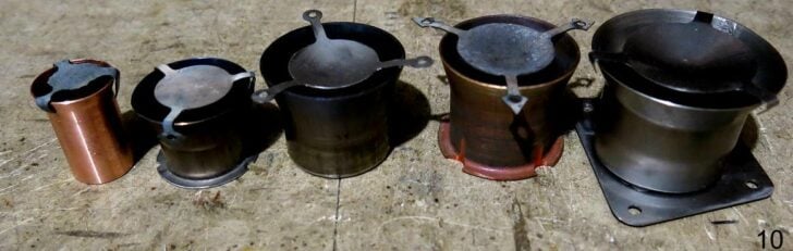
This photo shows some (not all) of the burner chambers I tested. But first let me deal with the other bits of the stove. I won’t cover the ‘new’ canister connector as that has been well covered in the V7 article. That leaves the hose and the legs.
The Hose
This uses PFA hose 2×1 mm. It was well covered in the V7 article, so I will just mention two small details.
The connectors at the two ends are now mostly symmetrical or the same, with plug-shaped ends or ‘inners’. The hose is 2.0 mm and the O-rings on it are 2.0 mm thick. That gives a total OD of 6.0 mm. The bore they go into is 5.6 mm. The difference is 0.2 mm on each side, which is 10% of the O-ring thickness, and meets the standard industry recommendation for O-ring compression (to get a good seal).
The braid is custom stainless steel, made for me in Taiwan. The crimp rings which hold the braid to the extension of the inner plug use a soft aluminium alloy which is just the right size for this. The diameter of the bit of the inner which holds the braid was adjusted to suit the available aluminium tubing.
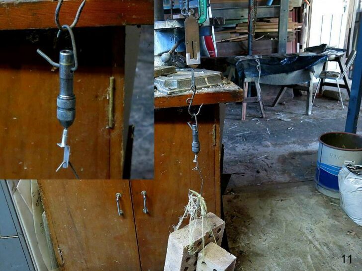
The crimping was done with another one of my crimp tools. The strength of the result was tested again: one does not want the braid sliding off.
The shiny bit below the hanging pin vise is a crimped bit of hose and braid. It is supporting 3 house bricks, which total about 9.5 kgf (21 lbf). That is enough.
The Legs
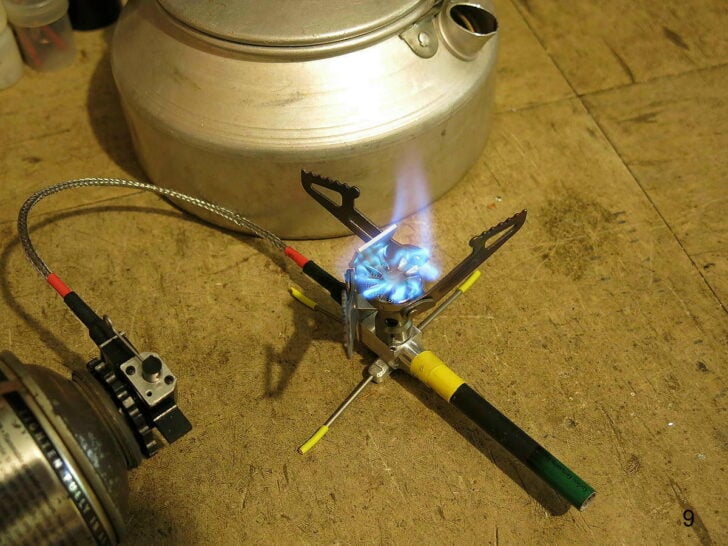
The legs on the V6 stove (shown here) were strong and functional, but they were not what I could call ‘elegant’. To be sure, they were very able to support a pot for 2 or 3 people.
The vertical part of the leg runs from the pot direct to the ground, and will not buckle. They are almost ‘too strong’. If I sacrificed a tiny bit of rigidity (not much), what could be done? Let us leap ahead past many experiments.
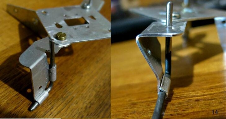
It did seem to me that the titanium Z-shaped legs are more elegant. The very short bits of aluminium that hold the bits of wire and pivot off the base plate are also far more elegant (and stronger). Ignore the M3 bolts holding the legs to the base plate: once the design was finalized they were replaced with suitable pop-rivets.
In coming up with this design I had to overcome some aesthetic problems. The first was that the simplest pivot leg held the Ti wire ‘off-centre’. That is, the wire did not point to the centre of the stove, but rather to one side. Aesthetics.
The photo on the left shows this. Some fiddling around with the design got the leg wire on the pivot axis, as on the right. At the same time the use of two crimps (left) was simplified to one crimp and one tight hole (right). The bend in the aluminium was done in my pan brake bender with a precise stop.
The crimp itself is worth mentioning: it has to be tight to stop the wire sliding around. I found that one of my crimp tools originally meant for electrical connections had a crimp-hole size just right for this. After crimping, the aluminium tab holds the Titanium wire quite tightly.
This titanium wire is 2.4 mm diameter. I also had 1.0 mm and 1.6 mm wire. The 1.6 mm wire was just a bit too bendy for my liking, so I am using the 2.4 mm wire. It is too hard to bend by hand to any degree of precision, so it is shaped in a custom wire bender I made for the job. This means every leg is identical (so to speak). With the custom wire bender, making each leg takes well under half a minute.
The Chamber and the Base Plate
I tried various smaller diameters of tubing (picture at the start of this section) for the chamber, but none of them seemed to work well enough. Why not? Examining the operation of a 25 mm chamber (copper pipe at the left of the picture), I found the flame did not make a sufficiently reliable vortex inside. On the other hand, perhaps it could work as pseudo-upright, but unfortunately the stove body still did not reliably get hot enough. A pity about that. I suspect the whole thing was just too close to all sorts of physical limits, like there was not enough room inside for the gas dynamics of a vortex flame.
Then I tried some 32 mm tube (also Ti, in middle). This gave a better flame than the 25 mm tube, but the vortex inside was not really reliable enough. Also, the only 32 mm Ti tube I could find on ebay had a 1 mm wall thickness. (Copper water pipe on the right of the Ti was readily available, but obviously very heavy.) The 1 mm wall thickness made the Ti tubing heavier than 38×0.5 mm Ti tubing (on the right) which I had been using before. So I was back to using the 38×0.5 tube – which I had in stock.
I found that both the shape and the area of the air inlets inside the chamber were significant. Much experiment followed. Logging the temperature of the aluminium base plate and the aluminium stove body with my LabJack data logger meant I could really see what was happening. The sensors used here are tiny NTC glass-bead thermistors, good to about 300 C. (Not the more readily available epoxy-encapsulated ones: the epoxy fails above 125 C. That is messy.)
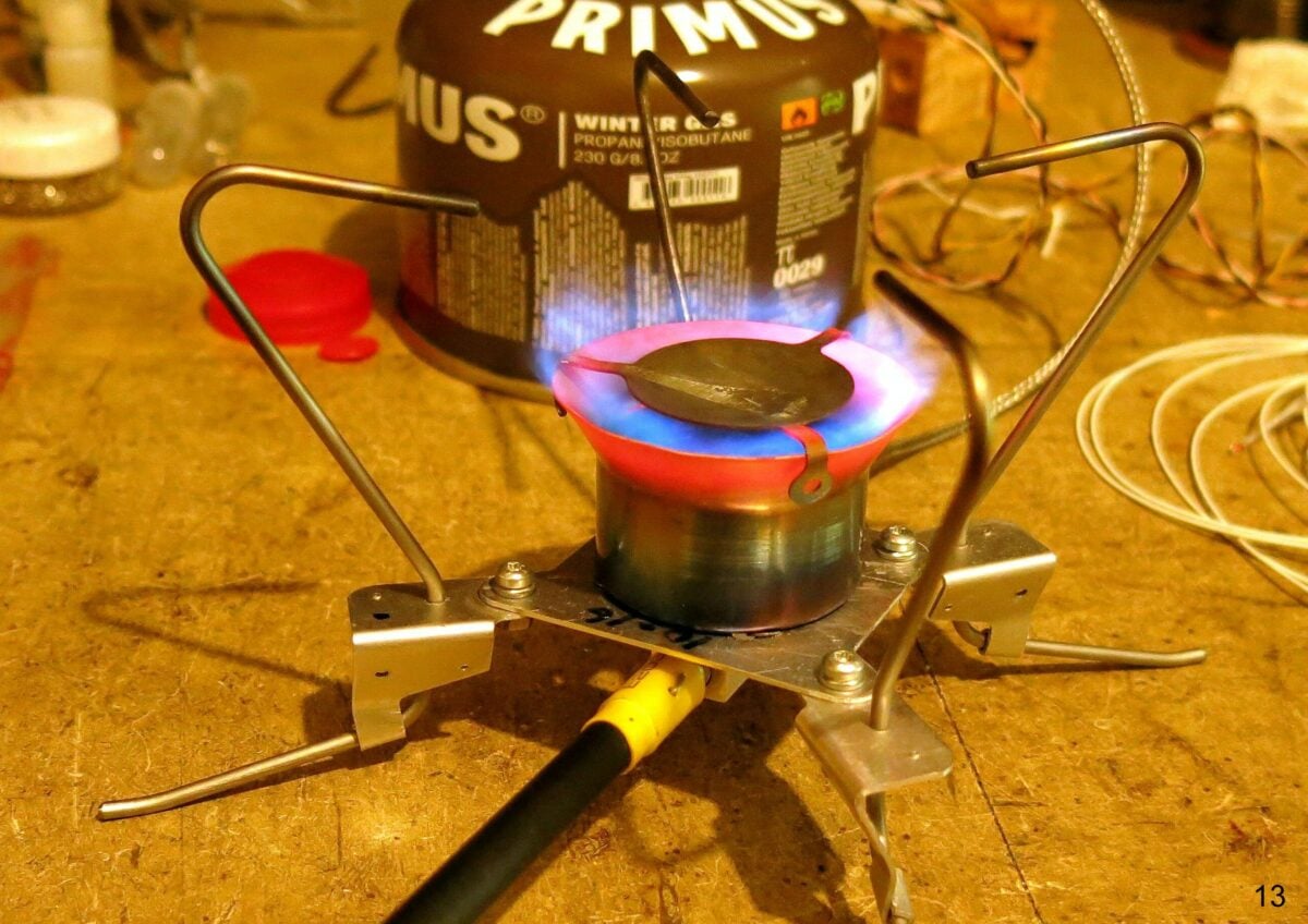
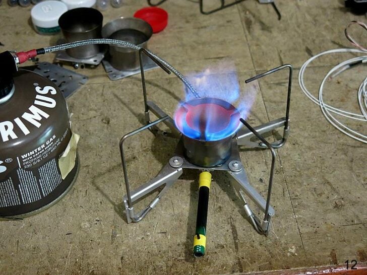
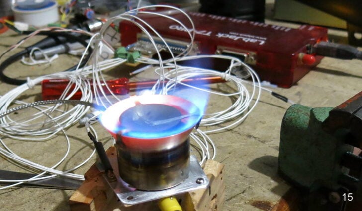
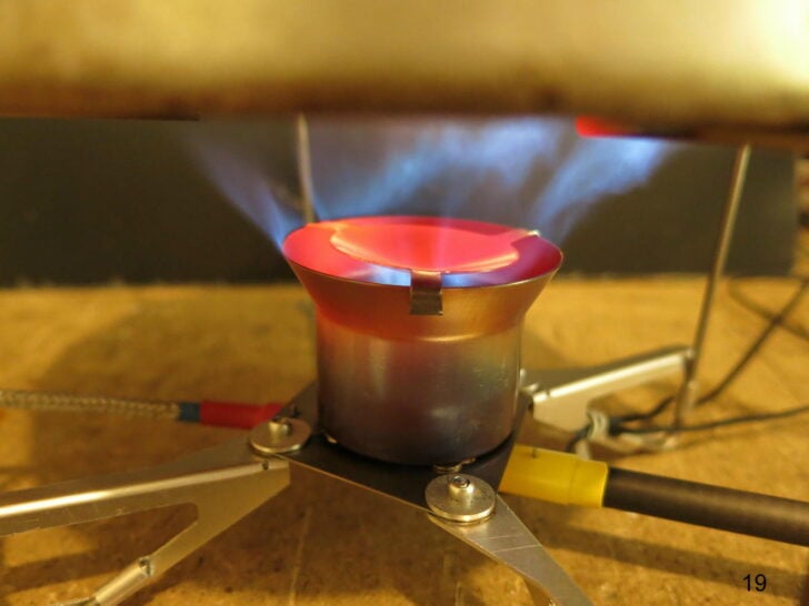
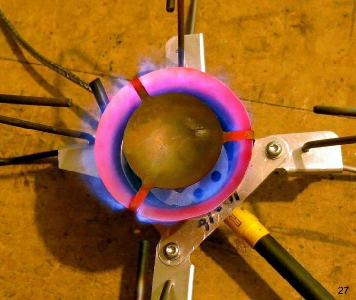
In this photo the thermistor for the base plate is inside the black ‘holder’ just to the left of the burner chamber. That is a copper tube bolted to the base plate and insulated with some black heat-shrink. The thermistor holder for the stove body is bolted to the stove body in the same way, but it is out of sight below the base. The white wires coiled up behind the stove are rather nice Teflon-coated (I think) thermistor leads: there are more of them than are being used here. (They come in bags of 10 on ebay.) The stove itself is on a wooden stand for testing. The rim is red hot, and the splash plate at the top nearly the same.
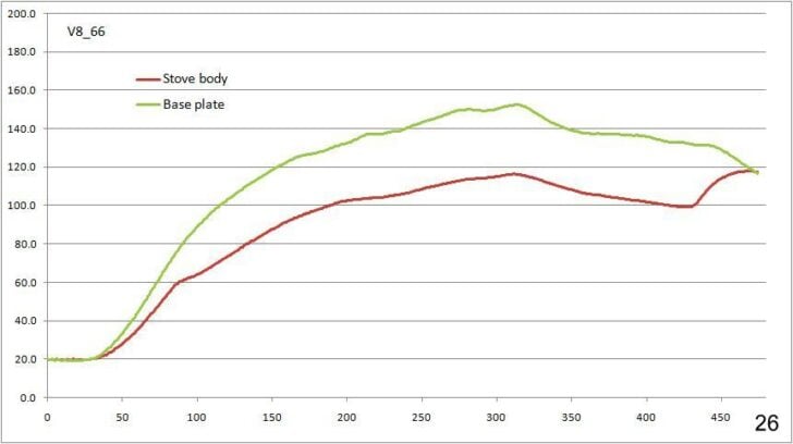
Anyhow, I shrank the aluminium base plate a bit: this was not a worry as those changes were all outside the burner chamber. Then I modified the design of the air inlet near the jet to vary the air flow. This change turned out to be rather consequential and took a lot of testing with much data logging. For instance, in this graph you can see where I varied the power level up and down in one test run.
This test run started with a gas feed (canister sitting upright), which was allowed to persist until about 250 seconds, when the canister was inverted. The 250 seconds is far longer than one should use in the field of course: I was distracted. The two temperatures rose steadily until the canister was inverted (250 sec) – when the amount of energy required to vaporize the incoming liquid fuel proved to be significant. The temperature rises stopped, with the stove body temperature really being limited. Around 320 seconds the power level or fuel flow was raised, when the temperature of the stove body actually fell a bit. This fall was despite the slight rise in the base plate temperature. Yes, there was more energy from the flames to the base plate and flowing from there into the stove body, but more fuel incoming meant more energy was being extracted out to vaporize the liquid fuel.
The next graph shows a test with a very short burner chamber. The splash plate is now closer to the base plate. The flames were pushed down by the lower splash plate to touch the base plate directly, with the contact transferring much greater amounts of energy from the flames.
In this case the stove was started with a gas feed (so no flaring), and switched to a liquid feed around 70 seconds. (There is a faint wiggle in the green curve.) The effect on the temperatures was barely noticeable as the heat radiating downwards was large. The two temperatures rose steadily. Around 200 seconds the power (fuel flow) was raised. One might expect (from the previous graph) that the temperature of the stove body would fall slightly due to the increased amount of energy needed to vaporize the increased amount of liquid fuel coming in, but not in this case. Instead the base plate got even hotter, and so did the stove body. It was touching 200 C when I shut the stove down: that is far too hot for the long-term health of the Viton O-rings and the PFA hose. I think the problem was the very low height of the burner chamber: that pushed the flames down too close to the base plate.
However, interpreting the results was not always that simple. This next case shows what can happen (and often does).
In this case the stove body was a bit warmer than the base plate due to a previous test. Ignore that, and look at what happened around 280 seconds. This was where the canister was switched off, and there was no more incoming fuel to vaporize. At this point the base plate was a lot hotter than the stove body, so heat still poured from the base plate to the stove body. Lacking any heat loss to incoming fuel, the stove body temperature climbed significantly, while the base plate cooled down quickly. When the base plate got a fraction colder than the stove body, around 325 seconds, both started cooling down.
The data presented so far implies that all the heat flow is through the base plate to the stove body, but this assumption became untenable after a while. It seemed that quite a bit of the heat flow was actually going through the brass jet, which was sticking up through the base plate, fully exposed to the flames, and not as shiny as the aluminium. It was absorbing a fair bit of heat.
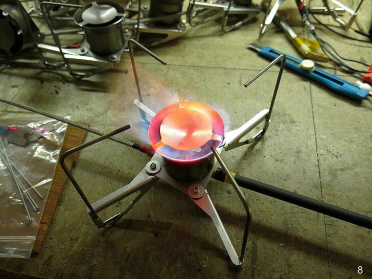
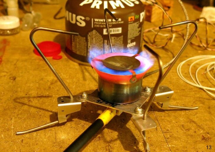
Looking at the photo here (yes, a V6 model, but it makes no difference), one can see that the splash plate on top is glowing red. This creates radiation down on the top of the jet as well as conduction by contact with the flame – if it is exposed. This would heat the jet and the stove body. So I designed something to test this idea.
I tested this idea by putting a tiny aluminium cap over the jet (with a hole for the gas through the middle of course) to block radiation and contact with the flames for the jet. This did lower the temperature of the stove body, but a loose cap over the jet was (obviously) not viable in the field, where it could get lost so easily. More creativity was required.
So I lowered the jet to below the base plate, and put a small hole for the gas in the plate. This worked to reduce the temperature of the stove body, but it created a problem and a large risk. The problem was how to remove the jet if/when it needed clearing – without completely disassembling the stove. OK, so make a larger hole and put a removable (rotates off to one side) cover plate over the jet, again with a hole in the middle for the gas to come through. This worked, but it created a very big risk. If any gas got deflected under the base plate, it would create a flame under the stove. This risk became a certainty if the hole in the cover was not in exactly the right place: lots of gas could be deflected sideways.
I have no pretty coloured 3D CAD pictures for these design changes as I find 3D CAD is too slow: instead I do most of the design in my head and use a simple 2D sketch program to record it. Then I program my CNC by hand.
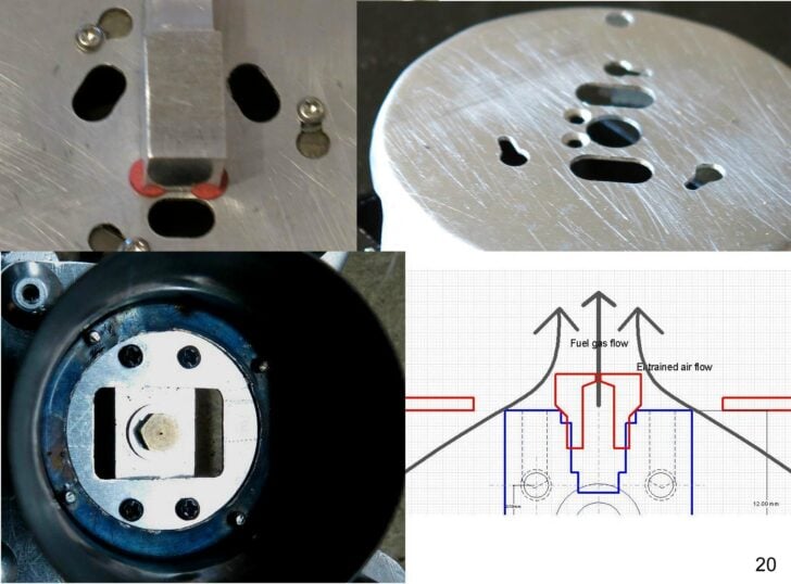
Despite these minor problems, it did seem as though the jet was sending a lot of heat into the stove body. How else could I cool it down? The next idea was to radically change the design of the air inlet. Instead of having two or three air holes around the jet (top row below), I would have one rectangular hole right over the jet (bottom row). This meant that the incoming air blasted the jet before being dragged upwards and this air cooled the jet down.
Detail note: the 4 off M2 bolts holding the burner chamber in this stove to the square base plate are clearly visible in the bottom left photo. The top row shows 3 bolt holes. Having only 3 holes was a bit inconvenient.
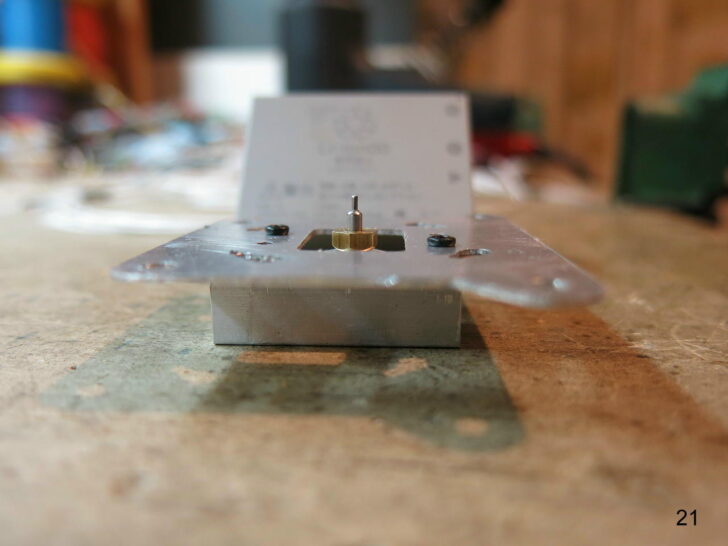
The idea of the air-cooled jet had some merit, but was it enough? Perhaps I could put the brass part down low but have the gas jet higher up? This was possible with some hypodermic tubing, as shown below. There should be ample room for air-cooling of the hypodermic jet and much less contact with the flames.
Short answer: it did not work. The jet and the gas flow were now so far above the rectangular air inlet, visible around the brass jet body, that it was no longer dragging enough air in. Lots of wobbly orange flames instead: just not good enough.
Along the way, while playing around with the size of the air inlet, I found (yet) another problem. If the fuel jet was sucking too much air into the chamber, the high gas flow out the top tended to blow out the flame on my Bic lighter. The gas might (rarely) get lit above the stove, but not inside the burner chamber where I wanted it. Clearly, one has to start with very low fuel flow, entraining only a little air. One could use a movable baffle to cut the air flow for starting (shades of the choke on an IC engine), but this is more complicated and one could lose the baffle in the field. Also, I found that the baffle got too hot for my fingers to adjust.
A solution was of course found: slightly shrink the size of the air inlet and start the stove on a very low setting. The combination reduces the blast of air past the Bic flame enough that the stove lights – neatly. Once there is a flame inside the chamber it is possible to turn the stove up a little bit. No, not full bore straight away: wait until the top rim or the splash plate is glowing a bit.
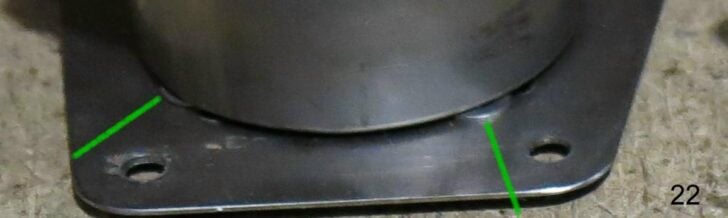
In all of this, and while working on V6 some time ago, I had considered the gap under the bottom rim to be insignificant. This gap is created by some M2 washers only 0.4 mm thick, placed on the M2 holding bolts to more or less isolate the very hot burner chamber from the base plate. The green lines point to them. I had never tested how well this worked.
While considering this matter of air flow, I tried increasing the air gap under the bottom rim by making much fatter ‘washers’. In fact, the gap was seriously increased by replacing the washers with 2 mm thick M2.5 nuts. Well, that was a very easy way to do it. So I tested the idea.
This graph is for the gap of 2.0 mm. The result was nothing short of startling: it could take a lot of priming to reach a stove body temperature high enough to allow conversion to a liquid feed if working in the snow. A very big OOPS! Or maybe ‘the light dawns’?
It made me rethink the whole matter of air flow: obviously a lot of air was coming in under the rim with this big gap – and it would still be coming in under a smaller gap. This ‘cold’ air was blowing over the base plate under the rim and had been cooling it down!
In addition, the vast excess of air coming in would be making the flames much cooler, which was not the objective at all. This is because so much energy would be taken up in heating the excess air, making the stove less efficient. It was time to consider some of the dimensions which were not all that well controlled in the past. That is, it was time for more focused trials.
The Effect of Dimensions
Two dimensions which have been discussed under previous stoves are jet size and Heat Exchanger clearance (at the hose end of the stove body).
Jet size is the major determinant of stove power: the more fuel burning, the hotter the stove. Stove design has very little to do with this. A very common jet size for many brands (including my own designs) is about 0.3 mm. This has to be drilled.
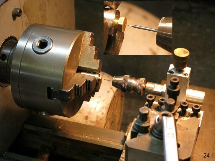
A 0.3 mm drill bit is very small, as you can see here. Swiss drill bits help.
We move on to the Heat Exchanger (HX). HX clearance affects how well the liquid fuel is vaporized, and has been covered in previous articles. Basically, the HX rod fills a hole just slightly larger in diameter, so the fuel travels past it in thin film around the edge, touching the stove body, and being vaporized.
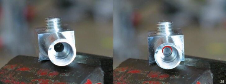
The photo on the left shows the dark empty hole for the Heat Exchanger (HX) rod; on the right the HX rod is in the hole. The thin gap between the HX rod and stove body is where the fuel flows, and it has been highlighted in red.
If the clearance between the HX rod and the hole in the stove body is too big, not all the fuel will be vaporised properly before it reaches the needle valve. For a more detailed discussion of this, read the articles on the V6 and V7 stoves. In practice the rod is 3.0 mm diameter and the hole is 3.2 mm, leaving a gap of 0.1 mm all around. If the HX rod is lost (it happens), then the stove tends to flare all the time.
Clearly the gap under the rim of the burner chamber will also be significant. I tested gaps of 0 mm, 0.3 mm, 0.4 mm, 0.6 mm, 1.4 mm, 2.0 mm and 4.0 mm (and used up a lot of gas in the process). Two things became clear. The first is that the gap under the rim does allow some extra air to be entrained by the jet, and this extra air is significant. If the gap is too large, and excess of air is pulled in. Equally, if a zero gap is used (direct contact between burner chamber and base plate) no air is pulled in, but it turned out that this has a significant effect.
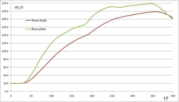
I did once (years ago) try to get heat flowing down an aluminium burner column to the canister underneath in an upright stove, but I failed totally. The flow of air through the air inlets near the base of the burner column was enough to totally block the flow of heat into the canister, or rather to absorb all the available energy coming downwards. This is exactly the same as how air coming in through the air holes in an upright burner cools the base, allowing you to unscrew it immediately you turn the stove off. The same effect occurs here: the flow of air under the rim significantly cools the base plate. This flow and this cooling do not happen with a zero gap, letting the base plate quickly climb to 200 C. (See first graph above, V8_57.) I had to quickly shut the stove down at this point or risk damage to the Viton O-ring and the PFA hose.
I found that a gap of about 0.6 mm gave a good result, and this could be done very easily by using 2 off 0.3 mm M2 washers on every M2 bolt.
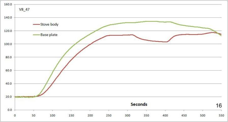
The canister was inverted around 80 seconds, the power was tweaked just a little around 200 seconds, and then turned to high around 320 seconds. The temperature of the stove body fell slightly when turned up to full power – as expected. The stove was turned off around 430 seconds and the cooling effect of the incoming fuel was lost. Heat from the hotter base plate then made the stove body hotter – for a little while.
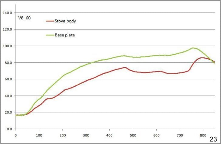
Finally, what about the diameter of the splash plate? I tested quite a few different diameters, and found that the diameter actually did not have a huge effect. Making the splash plate larger meant the gap between it and the top rim smaller, and it did seem as though this pushed the flames down a bit, to heat the base plate a bit more. But anything between 28 mm and 32 mm for the diameter seemed to work fairly well. The graph V8_66 above was for a 28 mm splash plate.
After a recent strenuous approach to an alpine area, headache, nausea, fatigue, and dizziness produced a Lake Louise AMS score consistent with moderate acute mountain sickness. Garmin data and a detailed reconstruction of food, fluid, workload, and sleep revealed a more complex event. This case study examines how altitude exposure interacted with carbohydrate depletion, dehydration, and accumulated fatigue – and why backcountry illness is often better understood as a convergence of physiological stressors.
Abstract
During a recent one-night backpacking trip to a high-elevation lake in a northern Colorado Wilderness area, I developed headache, nausea, fatigue, mild dizziness, chills, shakiness, anxiety, and temperature dysregulation several hours after arriving at an elevation of approximately 11,500 feet. A retrospective 2018 Lake Louise Acute Mountain Sickness (AMS) Score was 7, meeting the criteria for moderate acute mountain sickness. Garmin data and a detailed reconstruction of food, fluid, workload, and symptom timing also revealed substantial carbohydrate depletion, a large energy deficit, inadequate hydration, and pre-existing sleep debt. This case illustrates the difficulty of attributing symptoms to a single cause in mountain environments and demonstrates how altitude exposure, workload, nutrition, hydration, and recovery can interact.
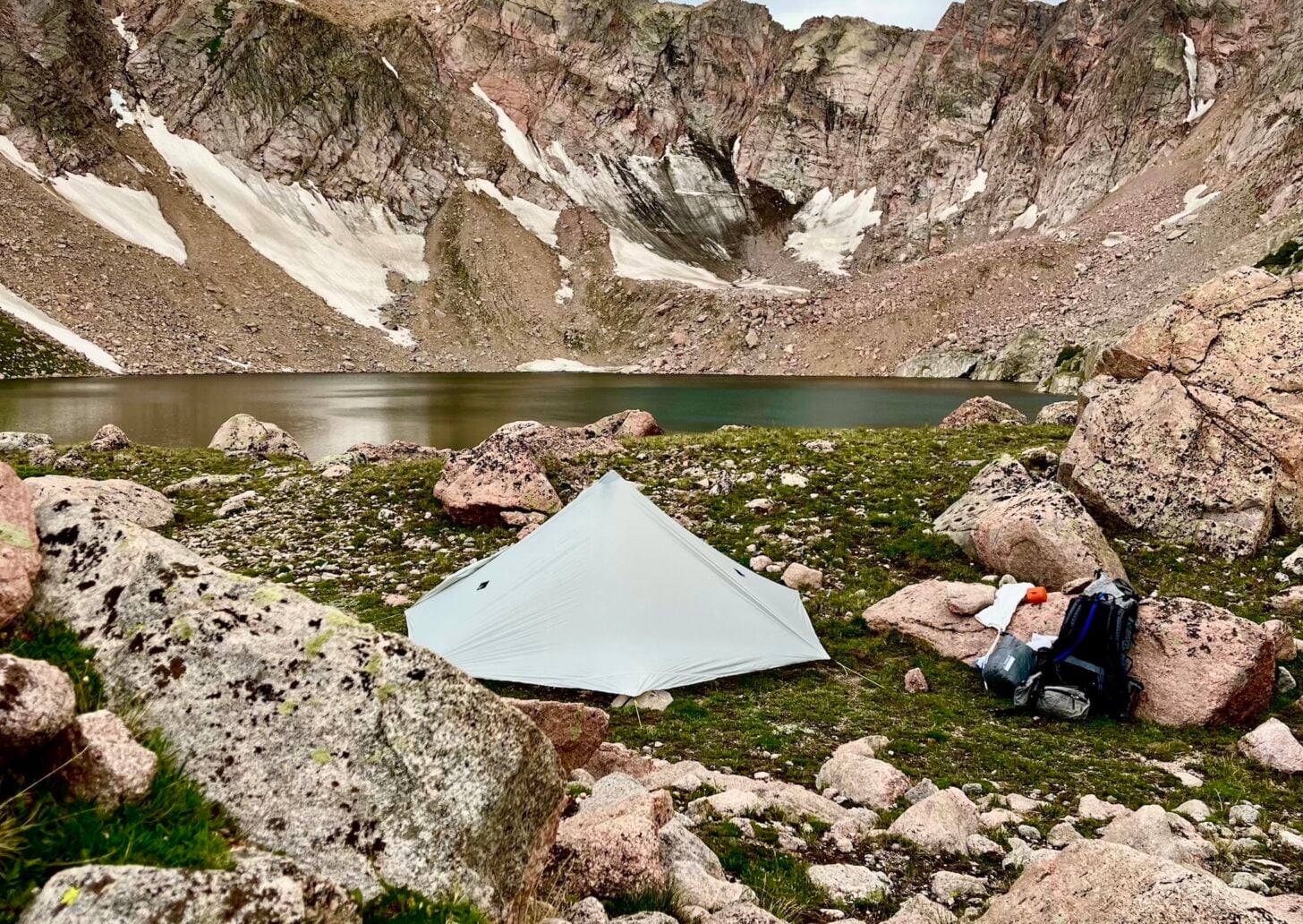
High camp at 11,500 feet, northern Colorado.
Context
I’ve been adventuring in the backcountry since I was a child and leading group trips and guiding clients for more than 30 years. By far, the most common medical issues I’ve faced personally, and with my hiking companions and clients of all ages, backgrounds, and fitness levels, are centered around the following four areas:
Dehydration
Metabolic fatigue
Gastrointestinal issues
Acute mountain sickness
It’s incredibly challenging to diagnose single contributors to any set of symptoms, since so many issues present themselves with shared symptoms.
To illustrate this, I present a case study from a recent hike, in which each of these four issues is analyzed in the context of observed symptoms, a detailed account of food and water intake, and recorded wearable data during activity and sleep.
Background
I live in Estes Park, Colorado, at 7,600 feet and am regularly active at higher elevations. Because of this baseline acclimatization, an overnight trip to approximately 11,500 feet would not ordinarily appear to represent an extreme altitude exposure for me.
The trip, however, combined a large increase in sleeping elevation with an unusually demanding approach. I hiked 13 miles, much of it off trail through dense forest and alpine terrain, climbed approximately 3,800 cumulative feet, and carried a 48-pound pack excluding water (I was caching food for a group of friends traveling through the area). With two liters of water, my starting pack weight was approximately 52 pounds, or about 32% of my 165-pound body weight.
I left Estes Park at 5:30 a.m. and started my hike at 8:11 a.m. at an elevation of approximately 8,600 feet. I reached my destination at 6:24 p.m. The net increase from my home to the sleeping elevation was approximately 3,900 feet.
Workload
The recorded activity lasted approximately 10 hours and 13 minutes. Garmin reported:
Average heart rate: 133 bpm
Maximum heart rate: 169 bpm
Total calories: approximately 3,740 kcal
Aerobic training effect: 5.0
Anaerobic training effect: 3.2
Recommended recovery time: 96 hours
Approximately 3.5 hours were spent at or above 142 bpm, including approximately 1.3 hours at or above 151 bpm. My aerobic threshold heart rate is about 150 bpm.
My performance declined substantially late in the day. I experienced increasingly heavy legs, weakness, an abrupt reduction in performance, and loss of hunger. During the final 1.73 miles, my average speed fell to approximately 1.10 mph while my average heart rate increased to 139 bpm. Although the final terrain was steeper, both physiological and subjective evidence indicate severe cumulative fatigue.
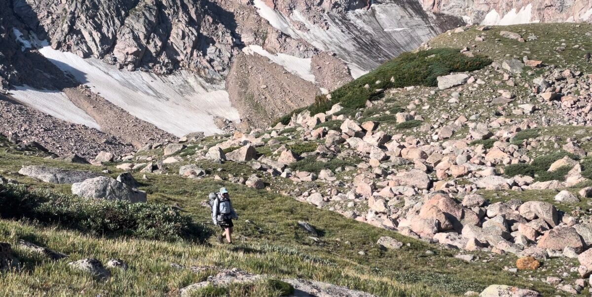
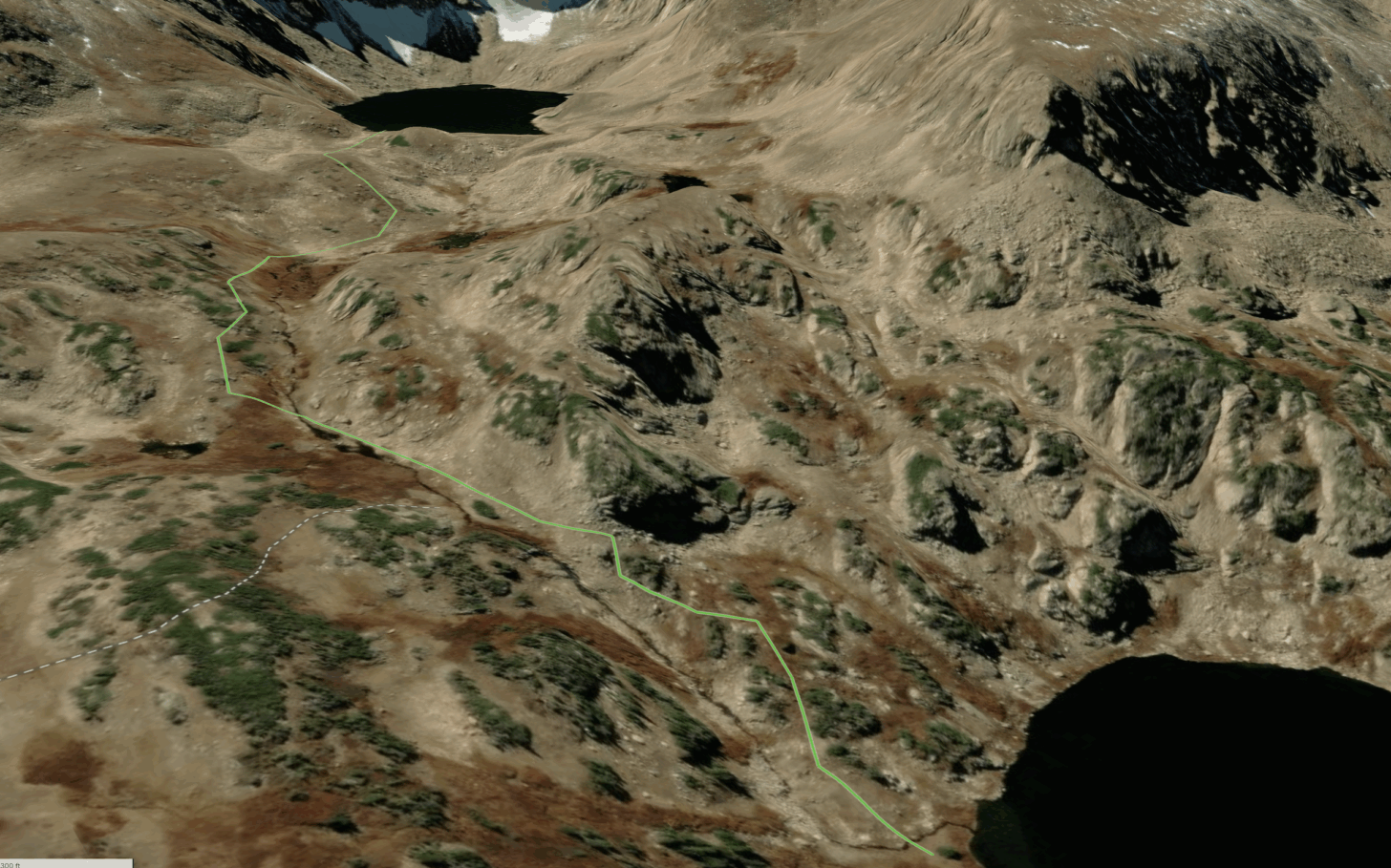
A 3D perspective from satellite imagery showing the final section of my route up to the lake where I camped (upper part of photo). Dark green = krummholz; reddish-brown = willows; dark gray = tundra vegetation; light gray = bare soil, talus and scree.
Food and carbohydrate intake
Dinner the night before the trip was relatively small: chicken Caesar salad with approximately two cups of romaine, two ounces of chicken, a piece of toast, two tablespoons of dressing, and one cup of berries. Estimated carbohydrate intake was only about 35 to 50 grams. I consumed no material amount of water after dinner.
Breakfast immediately before hiking consisted of two ounces each of beef sticks, dried fruit, and sunflower seeds, plus two cups of coffee. This provided substantial energy but only approximately 55 to 70 grams of carbohydrate. Much of its energy came from fat and protein and would not have been rapidly available during the opening hours of the hike.
During the approximately ten-hour approach, I consumed:
Three ounces of dried meat
Two ounces of dried fruit
One ounce of dry-roasted edamame
1.5 ounces of gummy bears
One ounce of almond butter
2.5 ounces of fig bars
This provided an estimated 1,070 to 1,290 kcal and 135 to 170 grams of carbohydrate. Average carbohydrate intake was therefore only about 13 to 17 grams per hour. Most of the dried fruit, gummy bears, and fig bars were consumed later in the day, after fatigue had already accumulated.
Dinner was eaten within approximately 30 minutes of arriving at camp. It consisted of four ounces dry weight of Food for the Sole Triple Peanut Slaw and 1.5 ounces dry weight of beef bone broth. The meal provided approximately 705 to 760 kcal but only about 55 to 70 grams of carbohydrate.
Estimated intake from breakfast through dinner was approximately 2,475 to 2,900 kcal and 245 to 310 grams of carbohydrate. Estimated full-day expenditure was 4,200 to 4,900 kcal. The probable end-of-day energy deficit was therefore approximately 1,300 to 2,400 kcal, with about 1,800 kcal representing a reasonable central estimate.
At a body weight of approximately 75 kg, total carbohydrate intake was about 3.3 to 4.1 g/kg. More important than the daily total were the low carbohydrate delivery rate during the hike and the limited carbohydrate replacement after exercise.
Hydration
Temperatures during my hike were in the 60s, and mostly overcast with slightly breezy conditions – a perfect day for hiking! However, the terrain was steep, relentlessly uphill, and I was carrying a heavy pack. Needless to say, this was not a sweat-free hike.
I consumed approximately two liters of water during the hike and another half liter with dinner. I consumed no electrolytes.
At 10 p.m., my urine was dark yellow, consistent with significant dehydration. Urine color returned to normal by mid-morning the following day.
Garmin estimated a very large sweat loss, but wearable estimates of sweat loss are too model-dependent to treat quantitatively. The combination of low fluid intake, prolonged exertion, carried load, concentrated urine, and subsequent normalization with fluid nevertheless provides strong evidence of dehydration.
Symptom development
I went to bed at approximately 7:30 p.m. Symptoms began around 10 p.m., approximately 3.5 hours after arriving at camp.
Symptoms included:
Throbbing temple headache
Nausea
Moderate fatigue and weakness
Mild dizziness or lightheadedness
Shakiness
Chills and feeling unusually cold
Anxiety
Later temperature dysregulation, including feeling unusually warm
A pounding, but not racing, heartbeat when nausea peaked around 1 a.m.
There was no sweating, confusion, vomiting, sustained tachycardia, breathlessness at rest, cough, loss of coordination, or other evidence of high-altitude cerebral or pulmonary edema.
At 1 a.m., I was feeling ill, desperate for relief, and anxious – my headache was moderately severe by this point. I had forgotten to pack analgesic and anti-inflammatory meds for headaches. After running through the Lake Louise protocol in my head, I knew AMS was a contributing factor. In addition, I had consumed no caffeine since morning, am a regular coffee drinker, and was thinking that maybe caffeine withdrawal could be presenting as well. In an effort to dilate blood vessels and give my head some relief, I consumed a couple of caffeine gummies (about 50 mg of caffeine) with 8 ounces of water at approximately 1 a.m., and within 30 minutes, had started to experience some headache relief. I fell asleep shortly after.
Sleep and overnight physiology
Garmin recognized only 3 hours and 45 minutes of sleep, from approximately 1:44 to 5:56 a.m., and assigned a sleep score of 34. My actual bedtime was approximately 7:30 p.m. (I went to bed early, intending to wake up for a pre-dawn start the next day). This suggested that Garmin failed to classify much of the earlier period as sleep because I was awake or sleeping too intermittently for my watch to reliably detect.
Overnight pulse oximetry averaged approximately 86%. By comparison, my average sleeping saturation the night after returning home to Estes Park was approximately 94% (normal for me at home). My normal overnight pulse oximetry during my first night above 11,000 feet, after sleeping at home, is usually 90% to 92%.
Other Garmin trends showed:
Increased overnight and resting heart rate
Modestly increased respiration
Limited Body Battery recovery
Severely reduced sleep duration and sleep score
Rapid normalization during the first night home
The wrist-derived pulse-oximetry value supports substantial nocturnal hypoxemia but cannot diagnose acute mountain sickness or determine its severity. Wrist measurements are affected by fit, perfusion, movement, temperature, and other sources of error. An average saturation in the mid-80s is also physiologically plausible while sleeping at an elevation near 11,500 feet.
Lake Louise Acute Mountain Sickness Score
That night, I scored my symptoms using the 2018 Lake Louise Acute Mountain Sickness Score: 0 = none, 1 = mild, 2 = moderate, and 3 = severe and incapacitating.
Symptom
Score
Headache
2
Gastrointestinal symptoms
2
Fatigue or weakness
2
Dizziness or lightheadedness
1
Total
7
A score of 3 to 5 represents mild AMS, 6 to 9 represents moderate AMS, and 10 to 12 represents severe AMS. The diagnostic definition also requires headache following a recent increase in altitude.
A score of 7 therefore meets the criteria for moderate acute mountain sickness. Sleep disturbance is not included in the 2018 score.
The score must be interpreted cautiously because several symptoms – particularly fatigue and GI distress – had plausible non-altitude causes.
Morning course and carbohydrate response
By morning, the headache and nausea had improved. I felt as though I had recovered somewhat overnight despite consuming no additional carbohydrate. I drank approximately 12 ounces of coffee and one package of bone broth but ate no solid food before leaving camp at 9 a.m.
I still had little appetite and did not eat until approximately 10 a.m., after descending about 700 vertical feet. At that point, I consumed:
Two ounces of dried fruit
One ounce of candy
One ounce of dried meat
Two ounces of chips
This supplied approximately 600 to 750 kcal and 90 to 105 grams of carbohydrate.
Within approximately 30 minutes, appetite, energy, and mental clarity improved markedly.
The speed of this response is important. Muscle glycogen could not have been substantially restored within 30 minutes. The immediate improvement was more likely due to increased circulating glucose and carbohydrate oxidation, partial restoration of liver carbohydrate availability, increased sodium and fluid intake, and reduced counter-regulatory stress.
A 700-foot descent may also have contributed, but the close temporal relationship between carbohydrate consumption and restored function provides strong evidence that low carbohydrate availability remained physiologically important.
Differential diagnosis
Moderate acute mountain sickness
The delayed onset of headache, nausea, fatigue, and dizziness after ascending to a new sleeping elevation is characteristic of AMS. Symptom onset approximately 3.5 hours after arrival falls within the expected time course. The retrospective Lake Louise score of 7 meets the definition of moderate AMS.
Carbohydrate depletion
The late-hike performance decline, heavy legs, weakness, loss of appetite, low carbohydrate intake, inadequate recovery meal, and rapid response to carbohydrate the following morning strongly support marked exercise-induced carbohydrate depletion.
True hypoglycemia cannot be confirmed because blood glucose was not measured. The more defensible conclusion is that I experienced physiologically significant low carbohydrate availability, with possible transient low circulating glucose.
Energy deficit
The estimated 1,300 to 2,400 kcal end-of-day deficit likely amplified fatigue, thermoregulatory stress, impaired recovery, and sympathetic activation.
Dehydration and sodium deficit
Low fluid intake and dark-yellow urine indicate meaningful dehydration. The absence of electrolyte replacement may also have contributed, although sodium losses were not measured.
Sleep debt
I began the hike after Garmin recorded only approximately 4 hours and 46 minutes of sleep the preceding night. This reduced my physiological reserve before a very demanding day and probably worsened overnight recovery.
Caffeine withdrawal
Caffeine withdrawal may have contributed to the headache because I consumed no caffeine after breakfast until 1 a.m. It does not adequately explain the full symptom complex, the altitude-specific timing, or the performance response to carbohydrate.
Final interpretation
This event was not adequately explained by a single diagnosis.
The most defensible classification is:
Moderate acute mountain sickness occurring in the setting of severe exercise-induced carbohydrate depletion, a large energy deficit, meaningful dehydration, high carried load, and pre-existing sleep debt.
AMS best explains the delayed nocturnal onset of headache, nausea, and dizziness after ascent. Carbohydrate depletion best explains the late-hike performance collapse and rapid restoration of energy and mental clarity after eating. Dehydration, energy deficit, and sleep debt reduced physiological reserve and likely increased the severity of both processes.
The overnight shakiness, anxiety, temperature changes, and pounding heartbeat were probably manifestations of a combined sympathetic response to altitude hypoxia, nausea, dehydration, depleted carbohydrate availability, and accumulated exertional stress.
Limitations
This analysis has several limitations:
Blood glucose was not measured.
Wrist pulse oximetry is not equivalent to medical-grade oximetry.
Food composition and energy expenditure were estimated.
Garmin calorie and sweat-loss estimates are model-derived.
Descent, rest, fluid, sodium, caffeine, and carbohydrate occurred close enough in time to preclude causal separation.
Fatigue and weakness were not specific to altitude illness after such a demanding approach.
Despite these limitations, the convergence of route data, physiological trends, symptom chronology, concentrated urine, Lake Louise score, and response to carbohydrate supports a multifactorial diagnosis with both altitude- and metabolic-related components.
Practical case-study lesson
The main lesson here is not simply that more food or water would have prevented AMS. Rather, altitude tolerance cannot be separated cleanly from total physiological load.
A person acclimatized to moderate altitude may still develop clinically meaningful AMS when a large increase in sleeping elevation is combined with prolonged exertion, a heavy pack, insufficient carbohydrate delivery, inadequate hydration, sleep debt, and incomplete recovery nutrition. In this case, each stressor probably remained individually manageable until their effects converged during the first night at high camp.
The descent.
Obviously, I could have mitigated some of the negative impacts from this trip:
Eating a carbohydrate-rich meal the night before to ensure replenishment of adequate glycogen stores.
Monitoring and replenishing hydration levels during the ascent.
Slowing down my pace so as not to operate at a metabolic effort so close to my aerobic threshold for such a long period of time.
Not starting the trip with a sleep quality deficit.
#1, #2, and #3 are choices you have control over in the moment. #4 is often the outcome of circumstances out of your control, especially if you are juggling work, family, and other obligations and commitments.
This trip reminded of me three important lessons:
First, if you are attempting a route that requires you to operate near your metabolic capacity within a specific frame of time (I needed to complete this route before dusk), starting the route with sleep, metabolic, fitness, or other types of deficits will put you at a disadvantage and reduce your margin.
Second, I’m still pretty durable. Many decades of mountain travel keep me grounded in the face of crisis and allow me to analyze them objectively and address them intentionally.
Third, I’m not invincible. I still make behavioral choices that incur costs later on. This is because I believe I’m more durable than I think. I’ve been fighting this psychological tendency my entire life, and it continues to be an Achilles heel that limits my performance. Most of the time, when I find myself in crisis, I come back to the truth: I’m my own worst enemy.
The combination of pack weight, effort intent, terrain steepness, and altitude has profound impacts on metabolic fatigue. This can be analyzed precisely using TRIPS – see the How to Plan with TRIPS masterclass.
The Durston Wapta 30 is a ~1 lb backpack made with Aluula fabric. In this review, we evaluated packbag stability, harness comfort, and usability in the context of its frameless design.
Introduction
The Durston Wapta 30 is a bit of an anomaly in the niche market of ultralight, small-volume, frameless backpacks in the one-pound range. It combines durable fabric (Aluula Graflyte), a padded hip belt and back panel, and a multi-pocket layout in a frameless design marketed with a strong emphasis on “comfort” and “refinement.”
Table of Contents • Note: if this is a members-only article, some sections may only be available to Premium or Unlimited Members.
Manufacturer copy, existing published reviews, and user feedback commonly frame the Wapta 30 around two ideas:
Aluula Graflyte as a novel ultralight pack material, and
Unusually high comfort/functionality for a small-volume frameless pack.
I’ve already addressed the attributes of Aluula Graflyte as a backpack fabric in Advances in Materials and Manufacturing in Ultralight Backpacks, so the reader is referred to that article for relevant materials context. In addition, I offer light commentary on Durston’s use of Aluula in the Wapta in the Other Observations section later in this article.
First, I want to address specific gaps and misunderstandings exhibited by most existing coverage of the Wapta 30. Specifically, previous reviews and commentary do not clearly distinguish between improved strap comfort, improved pack stability, and actual shoulder-to-hip load transfer of the Wapta 30. In many cases, reduced pack movement (stability) and comfortable shoulder straps are treated as evidence of an effective suspension without directly evaluating whether the hipbelt materially unloads the shoulders under increasing load.
In this review, I carried a few configurations of a typical mountain kit that included 3-season insulation, a solo tent, snow- and rock-scrambling equipment (such as the haul rope strapped to the top of the pack in this photo), and three days’ worth of food. Tested pack weights ranged from about 22 to 29 pounds.
This review evaluates whether the Wapta’s design materially improves frameless load-transfer mechanics, or whether its advantages are limited to fit, stability, and harness comfort.
This review compares the Wapta against similar volume packs serving different analytical roles:
Gossamer Gear Mirage 40 – an Aluula fabric structural counterexample with an internal frame.
Arc’teryx Alpha SL 30 – an Aluula implementation with bonded (not sewn-and-taped) construction and semi-structural load transfer through its bonded foam framesheet architecture, which resists torso collapse more effectively than conventional frameless designs despite lacking a traditional frame;
Traditional frameless packs – i.e., Pa’lante V2, MLD Burn, Gossamer Gear Murmur 36 Hyperlight, Atom Packs Atom, ULA Photon, and Zpacks Nero Pro 30 (baseline references for frameless mechanics with stabilization-oriented hipbelt behavior); and
Vest-harness packs – i.e., Gossamer Gear Grit 28, Nashville Cutaway, Hyperlite Mountain Gear Aero 28, Outdoor Vitals Skyline 30 Fastpack, and Black Diamond Beta Light 30 (baseline references for packs with bounce reduction and close-to-body carry stability.
Useful for asking whether Wapta’s additional complexity materially improves mechanical behavior over lighter frameless packs.
Structural Carry Analysis: Stabilization Versus Load Transfer
Durston positions the Wapta as a “highly comfortable” frameless pack – noting its padded hipbelt, ergonomic shaping, S-shaped shoulder straps, dual foam backpanel strips, and advanced construction. Existing reviews describe the pack as unusually comfortable at heavier weights for a frameless design. Most reviewers characterize the hipbelt as “load-bearing” or cite reduced shoulder strain under heavier carries.
These claims raise an important question: Does the Wapta’s harness and hipbelt system transfer weight from the shoulders to the pelvis, or is its main benefit enhanced stability, body control, and strap comfort?
Test Methodology and Evaluation Criteria
I loaded the Wapta and comparison packs with the same kit: a solo DCF tent, 30 °F down quilt, down jacket, insulated air mattress, mountaineering safety gear (traction, helmet, haul rope, and ice axe), trekking poles, cooking equipment, electronics, food storage, and three days of food.
My base weight (no food and water) was approximately 16.8 lbs (7.6 kg). Three days of food increased the carried load by an additional 4.5 lbs (2.0 kg), while water loads ranged from a typical 1 L carry to extended dry carries approaching 4 L. Total carried pack weights therefore ranged from approximately 22–29 lbs, depending on water carried, food remaining, and whether or not my trekking poles and mountaineering gear were in use or stashed.
Testing focused on three distinct but commonly conflated performance categories:
Stability: resistance to side-to-side pack movement, bouncing, and load shift during scrambling, running, bushwhacking, or other uneven movement;
Comfort: localized pressure management and resistance to hipbelt slippage under load;
Load transfer: the ability of the pack structure to distribute vertical load between shoulders and hips while resisting torso collapse.
These differences are important because any hipbelt – including a simple webbing belt – can improve pack stability by limiting lateral movement and resisting the pack from sliding downward. Likewise, wide padded shoulder straps and padded hipbelts can improve perceived comfort by distributing localized pressure. These characteristics alone don’t contribute much to shoulder-to-hip load transfer, the most important factor affecting comfort as pack weight increases. To understand the relationship between user-perceived comfort, torso collapse, and pack suspension performance, see Frameless Backpacks: Engineering Analysis of the Load Carrying Performance of Selected Lightweight Packs, How Packs Work, and Quantitative Analysis of Backpack Suspension Performance.
The Wapta’s 30L capacity provided plenty of room for a minimalist overnight kit, with room to spare for a few days’ worth of food. As food dwindles and packed volume decreases, you can see the effect of about 14 lbs (6 kg) of weight causing the pack to slump downward and place strain on the shoulder straps. The effect is somewhat mitigated, and overall carry comfort improved, by the wide, padded hip belt, which prevents the weight from pulling the hip belt downward.
Stability and Comfort
For moderate load ranges (up to about 15 lbs), the Wapta performs well by conventional frameless standards. The pack remains stable during scrambling and uneven movement, and its wide padded shoulder straps and broad padded hipbelt distribute localized pressure effectively. Compared to more minimal, frameless packs such as the Pa’lante V2, Murmur 36, Nero Pro 30, or Atom, the Wapta initially feels more comfortable under load because the user feels more padding (pressure relief) across a larger surface area, and more ergonomic straps across both shoulders and hips.
The hipbelt also performs well in resisting downward slippage. Once tensioned, it effectively stabilizes the pack against the pelvis and limits side-to-side movement during dynamic movements such as scrambling. In this respect, the Wapta’s belt functions more effectively than the minimalist webbing belts commonly found on frameless ultralight packs.
However, stability and pressure distribution should not be confused with suspension performance.
Load Transfer and Torso Collapse
As the carried weight exceeded approximately 16 to 18 lbs (7 to 8 kg), the Wapta performed more like a typical frameless pack. While the hipbelt continued to stabilize the load and resist slippage, it did not materially reduce the load on the shoulders during heavier carries. Instead, the pack became progressively more dependent on packing discipline and load structure to resist torso collapse. At weights exceeding about 21 to 23 lbs, torso collapse and the inability to unload the shoulders became significant enough to cause discomfort when wearing the pack for several hours a day.
Under heavier food and water loads exceeding about 24 lbs (11 kg), the Wapta exhibited visible rearward slumping and lower torso collapse, particularly as the packbag rounded outward in response to reaching its volumetric capacity. The result was an increasing downward pull on the shoulders despite the hipbelt remaining tightly tensioned around the hips. In practice, the belt stabilized the lower pack body without creating a sufficiently rigid load path between the upper packbag and pelvis.
Heavier loads (> 15 lbs / 7 kg) and loads under the pack’s usable volume capacity cause noticeable hinging in the unsupported area between the lumbar pad and vertical back panel padding. Lack of support here causes torso collapse, which is common in frameless packs.
Several design elements may contribute to this behavior. The dual foam backpanel strips create localized padded contact zones, but the unpadded channel between the bottom of the strips and the top of the lumbar padding reduces torsional continuity across the back panel. Likewise, the padded lumbar interface and broad hipbelt improve perceived comfort but are not mechanically coupled to a framesheet, stay system, or other vertical structural element that can maintain load transfer as pack weight increases.
The Wapta, therefore, behaves less like a semi-structured pack and more like a refined, frameless soft pack, whose comfort depends substantially on surface padding, load stabilization, and minimizing weight to less than 20 lbs (9 kg), rather than on frame-mediated load distribution.
Comparative Context
The contrast with the Arc’teryx Alpha SL 30 is particularly revealing. Despite similar pack volumes and broadly similar packbag geometry, the two packs allocate weight and structural complexity very differently. The Wapta emphasizes padded comfort features – broader and more padded shoulder straps, a padded hipbelt, lumbar padding, and dual foam backpanel strips – while the Alpha SL 30 uses a minimalist webbing belt coupled to a bonded thermoformed foam framesheet integrated directly into the pack body.
In both laboratory and field testing, the Alpha SL 30 resisted torso collapse more effectively under increasing load despite having substantially less perceived padding comfort. Under heavier carries approaching 25 to 30 lbs (11 to 14 kg), the Wapta increasingly slumped rearward and concentrated downward load onto the shoulders, while the Alpha SL maintained better vertical structure but transferred increasing pressure directly into the hips via its unpadded webbing belt. In other words, the Wapta initially feels more comfortable thanks to its padding, while the Alpha SL more effectively preserves load transfer due to its semi-structured back panel architecture.
Torso collapse vs. pack weight. Some of these results were originally published in Advances in Materials and Manufacturing in Ultralight Backpacks: A Technical Review and Case Study, where the Durston Wapta served as the blind control (red chart points), and the Alpha SL 30 was the primary test case (blue points). For this review, we added data from a pack that featured a sewn-in foam back panel (Hyperlite Mountain Gear Aeros 28, green chart points). The test is performed using an engineered human torso model that precisely measures torso collapse in a spring-loaded system as pack weight is added.
This comparison is important because much of the existing Wapta discourse conflates comfort with suspension performance. The Wapta is not uncomfortable for a frameless pack. In fact, it is unusually refined in terms of harness feel, stability, and pressure distribution. But those characteristics should not be mistaken for meaningful frame-like load transfer. Mechanically, the Wapta’s load-bearing performance is much closer to conventional frameless packs such as the Burn, Murmur, Nero, Atom, or Pa’lante V2 than to packs with genuinely structural load-transfer systems such as the Mirage 40 or Alpha SL 30.
Other Observations
Fabric, Taping, Materials, and Construction
Unlike the Aluula implementation used in the Arc’teryx Alpha SL 30, the Wapta 30 relies on conventional sewn-and-taped construction rather than molecularly bonded seams and integrated bonded structural panels. This difference is notable because much of Aluula’s long-term structural and waterproofing potential appears to be tied not only to the fabric itself but also to the manufacturing methods used to integrate it into the pack architecture.
The Wapta’s taped seams are less expensive and easier to manufacture, but they retain the conventional limitations of seam tape, including hydrolysis, edge peeling, and interior abrasion over time. After several months of intermittent use, including substantial exposure to rain and snow, I observed only minor edge peeling on the seam tape. At this stage, however, it is too early to draw meaningful conclusions about long-term durability, as seam tape often exhibits minor early peeling that does not progress immediately to structural failure.
More broadly, the Wapta does not fully exploit the most technically ambitious possibilities of Aluula-based construction, as the Alpha SL 30 does through the bonded integration of structural components. Instead, the Wapta applies a premium laminate fabric to a more conventional ultralight backpack construction methodology.
That difference is not necessarily a criticism. In practice, the Wapta still appears highly suitable for off-trail use, scrambling, and bushwhacking, where abrasion resistance and low water absorption offer material benefits. But it does create an interesting philosophical tension within the design. The pack appears heavily optimized around durability-oriented materials while simultaneously relying on comfort-oriented soft components – particularly spacer mesh and airmesh padding – that are often among the first materials to degrade over long-term use.
The most likely long-term failure points are therefore unlikely to be the Aluula laminate itself. Instead, they are more likely to involve the airmesh used in the shoulder straps, lumbar pad, and dual backpanel strips, particularly where those materials are bound into seams and repeatedly exposed to abrasion, moisture, and tension/compression cycles.
This creates a somewhat ambiguous use-case identity. The Wapta presents itself as both a highly durable technical mountain pack and a comfort-oriented ultralight backpack, but those goals occasionally feel in tension with one another.
Durability, Off-Trail Use, and Water Resistance
In practical use, the Wapta performed well in off-trail terrain involving alpine rock, scrambling, steep snow climbing, and bushwhacking. Aluula Graflyte remains one of the most compelling modern pack fabrics for this type of use because it combines low water absorption, good abrasion resistance, and relatively high structural stiffness at low weight.
The Wapta’s narrower pack profile contributes positively here. Compared to wider or more bulbous frameless packs, it feels less prone to snagging on rock, brush, or branches while moving through complex terrain. This gives the pack a more streamlined “backpacking’ feel rather than the high-riding, externally bulky sensation common to some fastpack-style vest packs.
Water resistance was also good in sustained precipitation. The laminate itself absorbs very little moisture, and the pack did not exhibit meaningful wet-out behavior during testing. As with most sewn-and-taped ultralight packs, however, long-term waterproofness is likely to depend less on the laminate and more on the longevity of seam-tape adhesion and soft-component integration.
Packbag Shape and Design
The Wapta uses a relatively tall, narrow pack shape. My size Large measured approximately 26 inches tall when fully loaded with the extension collar extended, roughly 10 inches wide, and approximately 8 inches deep.
Tall, narrow, frameless packs with high height-to-circumference ratios are inherently more prone to barreling and torso-height “hinging” than shorter, wider designs, particularly when they lack a framesheet or vertical stay structure. In the Wapta, this behavior was most noticeable under high-volume loads (barreling) or when the pack was underfilled (hinging). The packbag tended to round outward, minimizing contact area with the back when fully loaded, and hinging near the hipbelt region contributed to the torso-collapse behavior discussed earlier in this review.
The Wapta 30 is very close to the ideal shape and size I want out of a small overnight pack – large enough for a minimalist kit, small enough with a slim profile for easy bushwhacking and scrambling, and functional enough to provide access to gear outside the main packbag.
At the same time, the narrow profile improves mobility in technical terrain. The pack feels sleeker and less obtrusive than many wider frameless packs, particularly during scrambling or bushwhacking, where pack width directly affects maneuverability. In this respect, the Wapta feels more like a streamlined alpine backpacking pack than a high-riding fastpack.
The downside is that the narrower backpanel footprint limits how effectively the pack can wrap around and conform to the torso under load. Once the pack begins barreling outward, the limited backpanel contact area reduces the ability of the compression system and hipbelt to “pull” the load inward toward the user’s center of mass.
Pocket Configuration
The Wapta’s pocket configuration is conventional and generally effective for a pack in this volume class. It includes dual side pockets, a rear stretch pocket, shoulder strap pockets, hipbelt pockets, and an underbody stash pocket.
Pocket volume, however, is relatively conservative throughout the design. This is expected given the Wapta’s overall size, but it does impose practical limits on external storage flexibility compared to some larger-volume frameless and fastpack competitors.
The side pockets accommodate one-liter bottles and are easy to access without taking the pack off. Zippered hip belt pockets are usable and secure, though their effective volume decreases substantially once the padded belt wraps around the user’s hips. In practice, I could store approximately 500 calories of dense snack food per pocket before access and usable volume became constrained. This isn’t unique to the Wapta; it’s just the nature of having the hip belt pocket sewn into the hip belt, rather than floating with it.
The stretch-mesh shoulder pockets are tall and narrow. Smaller items, such as satellite messengers or compact phones, tend to sink deep into pockets, while larger cylindrical bottles fit awkwardly due to the relatively small pocket circumference.
Overall, the Wapta’s pocket layout feels optimized to minimize external bulk and preserve the pack’s narrow profile, rather than to maximize external-access storage capacity. That said, I found the pocket configuration and size to be functional enough for my usual distribution of gear:
Large rear pocket – poop kit, water treatment kit, 3L water bladder storage, rain jacket (this pocket was overfilled when I was carrying extra water and was not tall enough to protect my entire 3L bladder).
Left side pocket – 1L water bottle (was not secure enough to prevent the bottle from falling out while scrambling)
Right side pocket – trekking poles, tenkara rod, and tent poles
Underbody stash pocket – hat, gloves, and wind shirt (very tight fit)
Left shoulder strap pocket – cell phone, 5000 mAh battery & satellite messenger (tight fit)
Right shoulder strap pocket – mini notebook & pen, reading glasses (inconvenient access due to pocket shape)
Left hip belt pocket – lip balm, sunscreen, mosquito repellent, headnet
Right hip belt pocket – snacks
Daisy Chains and Webbing
The Wapta uses laser-cut Aluula Durlyte strips as rigid daisy chains sewn into the packbag’s vertical seams and along the front of the shoulder straps. These daisy chains accommodate Durston’s thin 5 mm nylon webbing, which is used for side-panel and top-panel compression.
The Durston Wapta 30 uses laser-cut Aluula Durlyte strips for daisy chains (two vertical ones along each side, and one shorter chain on each shoulder strap. 5 mm nylon webbing is threaded through holes in the daisy chain and knotted with stopper knots for security.
This is a novel, lightweight alternative to conventional sewn webbing daisy chains. The Durlyte strips are stiff, dimensionally stable, and likely lighter than equivalent webbing attachment arrays. In principle, this system gives the Wapta a modular compression and lashing architecture without adding much weight or water absorption.
In practice, however, the system is less field-adjustable than it initially appears. Moving a strap requires untying an overhand knot, threading the strap end through a different Durlyte slot, and retying the knot. That is manageable at home, but awkward with cold hands, gloves, fatigue, or wet/frozen cordage. The Durlyte itself also has a hard, sharp-edged feel; on one occasion, while tired and trying to manipulate the thin webbing with cold fingers, I scraped my hand along the strip’s edge and drew a little blood.
This is a minor issue for users who rarely reconfigure pack straps. But it became more noticeable when adjusting the pack for variable load volumes or external gear carry, including snowshoes, an ice axe, trekking poles, or a haul rope. In those contexts, the system felt more like a lightweight, fixed-attachment grid than a truly field-adaptable lashing system.
The Durlyte daisy chain concept shows promise, especially as a lighter, less absorbent alternative to traditional webbing daisy chains. But the current implementation would benefit from a more glove-friendly strap interface, softer edge treatment, or a faster way to reconfigure compression straps in the field.
Buckles and Hardware
The Wapta uses low-profile hook-style compression buckles rather than conventional side-release buckles. These buckles reduce weight and bulk while maintaining a flatter profile against the pack body, and they visually align with the pack’s broader minimalist and weight-conscious design. In theory, they are said to be less prone to accidental release and may reduce snagging compared with protruding side-release hardware, but these are dubious edge claims with little data to back them up.
The Wapta’s compression system consists of 5 mm webbing, compression-style side-release buckles, and stiffened fabric daisy chains. It’s usable and functional, but requires fine motor skills to operate and adjust that are not easily extendable to cold temperatures. Fortunately, the user can replace the straps and buckles with other hardware.
In practice, I find these types of buckles more finicky than conventional side-release buckles. They require relatively precise alignment during engagement, particularly if the connecting straps are under some tension, and were consistently harder to manipulate with cold fingers, gloves, or fatigue. Unlike a conventional side-release buckle (which can often be clipped blindly through broad self-aligning geometry), the Wapta’s hardware requires a more deliberate insertion angle and seating motion before locking positively into place.
The buckles also feel somewhat fragile relative to traditional side-release hardware. I did not experience any failures during testing, but the thinner hook arms and smaller engagement surfaces inspire less confidence during repeated cold-weather use or when aggressively tensioning compression straps around awkward external loads such as snowshoes or climbing equipment. Of note, the narrow (5 mm wide) webbing twists easily within the buckle slots when the buckles are tightened at awkward angles, causing slippage.
None of these issues is severe in isolation. But in practical field use, the system prioritizes minimalism and visual refinement over tactile ease of use and robustness, which occasionally felt at odds with the pack’s otherwise performance-oriented positioning.
Recommendations and Summary
The Wapta 30 is best understood as a premium, durable, comfort-forward frameless backpack for low-volume, disciplined ultralight loads – not as a meaningful advance in frameless load-transfer mechanics. Its strengths are material: state-of-the-art fabrics, low water absorption, a narrow off-trail-friendly profile, load stability, comfortable shoulder straps, a padded hipbelt that resists slippage, and unusually robust pocket and lashing features for a pack that weighs only about one pound. For users carrying compact kits at modest weights, especially in wet, abrasive, off-trail environments, it is a compelling design.
But the Wapta is not optimized for loads exceeding 20 pounds or bulky gear. Above modest loads, the pack behaves like other frameless packs: the hipbelt stabilizes the load and improves comfort at the pelvis, but it does not create meaningful shoulder-to-hip load transfer. When pushed toward 25 to 30 pounds, torso collapse, packbag barreling, and shoulder loading become the limiting factors. In this respect, the Wapta’s comfort features improve the interface between pack and body more than they improve the pack’s underlying structure.
The pack is therefore most appropriate for users who already understand the discipline of packing a frameless backpack: dense loads, low food volume, limited water carry, compact shelters, compact insulation, and careful attention to packbag structure. It is less appropriate for users expecting the padded hipbelt to perform like a suspension system, or for hikers who routinely carry bear canisters, heavy food loads, long water carries, or externally lashed technical gear.
If I were redesigning the Wapta for its apparent use case – durable, wet-weather, off-trail ultralight backpacking – I would not add more padding. I would add structure. A thin bonded foam framesheet would do more to improve real load transfer than the current foam strips and padded lumbar interface. A minimalist semi-structured system, closer in philosophy to the Arc’teryx Alpha SL 30 than to a fully framed pack, could reduce torso collapse while preserving much of the Wapta’s weight advantage.
I would also update the external interface. The Durlyte daisy chains and thin webbing system are clever, but not especially glove-friendly or easy to reconfigure in the field. The hook-style buckles save weight, but they are more finicky and less confidence-inspiring than conventional side-release buckles. For a pack that otherwise invites off-trail, shoulder-season, and technical terrain use, I would prioritize cold-hand operability, easier strap relocation, softer daisy-chain edges, and more robust buckle ergonomics.
Finally, I would reconsider the use of airmesh in high-abrasion zones. The Aluula fabric is likely not the weak link. The softer comfort materials (the shoulder strap mesh, lumbar pad, hipbelt padding, and backpanel strips) are more likely to determine long-term field durability. A version of the Wapta optimized for durable off-trail use would lean more heavily into structural integration and abrasion-resistant body-contact materials rather than adding comfort features that may age faster than the pack fabric itself.
The Wapta 30 is a unique and very good frameless backpack, but it is still a frameless backpack. Its most important contribution is not that it solves load transfer at ultralight weights, but that it combines high-end laminate materials, good pressure-point distribution across the collarbones and hips, and a stable, narrow profile in a refined, low-volume package. The central limitation is that its design language implies more suspension capability than its structure can actually provide.
The Wapta 30 is a frameless ultralight backpack built from Aluula Graflyte V-98 with Aluula Durlyte daisy chains, seam-taped construction, removable 3D-shaped hipbelt, S-shaped shoulder straps, 28-32L internal volume, and weights from 17.8-18.9 oz / 500-540 g.
The Men's Odin Infinity Minimalist Jacket is a 250 g 3.5-layer shell jacket using HELLY TECH PROFESSIONAL and LIFA INFINITY waterproof-breathable construction, with fully seam-sealed 2-way stretch fabric, helmet-compatible adjustable hood, RECCO reflector, zippered chest pocket, adjustable hem, and packable pocket.
The Arc'teryx Alpha SL Jacket is an alpine shell built with GORE-TEX PRO ePE and 20D Hadron face fabric, with a fully adjustable helmet-compatible StormHood, packable minimalist construction, PFAS-free membrane, and low-profile RECCO reflector. 232 g (8.2 ounces).
The Patagonia Men’s M10 Anorak is a slim-fit 3-layer waterproof alpine shell using a 20-denier recycled nylon ripstop face, RECCO reflector, Xpore nanoporous membrane, jersey backer, waterproof two-way front zipper, helmet-compatible hood, self-stuffing chest pocket, and 300 g (10.58 oz) weight.
We use a simple and repeatable shower test method to evaluate backpack water resistance that incorporates fabrics, closures, seepage, and material water absorption.
Backpacking packs often ride on the coattails of their fabric specs. Whether it’s abrasion resistance, tear strength, or water resistance, the extent to which a finished product’s performance matches the specs of its fabrics depends on how the pack is designed and constructed. In this context, we use a simple shower test to assess the water resistance of backpacks, evaluating not only their fabrics but also their seams and closures.
Backpacking packs are not necessarily “waterproof.” Even when they use waterproof or highly water-resistant fabrics, water can still enter through seams, stitch holes, zippers, roll-top closures, hydration ports, drawcord collars, and strap anchors. In the field, during sustained heavy rain, a fabric may resist wetting very well, while the pack system as a whole still allows water to seep into the packbag.
Herein, I describe a simple shower-based method to evaluate practical water resistance in a backpack. The goal is not to reproduce every variable of a real storm. Wind, pack movement, body heat, abrasion, shoulder-strap water tracking, and long-duration saturation all influence real-world performance. Instead, this method provides a controlled, repeatable, and practical way to screen for water ingress under a short-duration, high-intensity exposure.
This test is intentionally simple. It uses a household shower, a packed backpack, and a large cotton pillowcase as the internal witness material.
Table of Contents • Note: if this is a members-only article, some sections may only be available to Premium or Unlimited Members.
This method is designed to answer one practical question:
After a controlled 30-minute shower exposure, how much water enters the pack’s main compartment?
In addition, the test must provide the minimum viable conditions capable of differentiating the water resistance of different backpacks with materially different water-resistance behavior (fabrics, construction, etc.).
The method is not intended to certify a pack as waterproof. It is a comparative screening test that helps identify obvious or meaningful leakage through construction features such as seams, closures, zippers, and panel interfaces. Moreover, the method is best used as a screening tool to compare different backpacks, not as a predictor of water ingress in an actual rainstorm while the pack is being worn, placed on the ground, sat upon, and intermittently accessed.
Test Summary
The backpack is packed with a standard backpacking kit – sleeping bag and pad, shelter, poles, cook kit, extra clothing, accessories (e.g., first aid kit, toilet kit, water treatment kit), and enough food to bring the pack’s volume up to near its maximum capacity.
A cotton pillowcase large enough to line the entire pack is used as a witness (absorption) material. Inside the pillowcase is a waterproof pack liner (a 5-mil plastic trash compactor bag). All gear is packed inside the pack liner. The pack liner is then roll-topped and taped shut to eliminate water entry, and extra pillowcase fabric is folded over the top.
The pack is exposed to a cold shower oriented at a 70-degree angle to the pack. The water spraying onto the pack covers about 250 square inches at a rate of 1.5 gallons per minute, equivalent to a rainfall rate of about 80 inches per hour. The test runs for 30 minutes.
A packed backpack is leaned upright in the corner of the shower, the flow rate adjusted to about 1.5 gallons per minute, and aimed at the upper front edge of the pack (red arrow). The area of wetting is sufficiently large (yellow-shaded region), and the test duration is long enough (30 minutes) to keep all exterior surfaces of the pack wetted for nearly the entire test.
After the water is turned off, the pack is left undisturbed for another 30 minutes to allow delayed seepage and capillary migration to occur. The outside of the pack is towel-dried and carefully opened, at which time the gear and pack liner are removed, and the pillowcase is removed, inspected, and weighed. The empty pack is weighed and compared with its dry weight to assess the total amount of water absorbed by the pack’s materials.
Witness Material
The witness material for this test is a cotton pillowcase large enough to line the pack’s entire interior.
A cotton pillowcase works well because it is simple, inexpensive, absorbent, and easy to inspect visually for wetness.
The pillowcase is not intended to identify every leak source with laboratory precision. Its purpose is to reveal whether water entered the main compartment in a way that is visible, meaningful, and relevant to real backpacking use.
Dwell Period
After the 30-minute shower exposure, the water is turned off, the pack is left closed and undisturbed for 30 minutes.
This dwell period is important. Some water ingress occurs after active spray stops, as water migrates through seams, stitch holes, zipper tapes, binding, folded closures, and fabric interfaces. Opening the pack immediately may miss some delayed seepage.
Rating Categories
In addition to the water weight absorbed by the pillowcase, results are reported using the following qualitative categories:
Rating
Observation
No visible ingress
Pillowcase appears dry after exposure and dwell period.
Minor ingress
One or more small isolated wet spots are present, but no broad wetting or pooling is observed.
Moderate ingress
Multiple wet spots or a larger localized wet area is present. Water entry is meaningful but not catastrophic.
Significant ingress
Pillowcase shows broad wetting, saturation in one or more areas, or evidence of water pooling inside the pack.
Severe ingress
The pillowcase is extensively wet or saturated, indicating that the pack failed to protect the main compartment under the test conditions.
Interpretation
A pack that performs well in this test is not necessarily waterproof. However, if the witness pillowcase remains dry after 30 minutes of calibrated shower exposure and a 30-minute dwell period, that is meaningful evidence that the pack resists short-duration, high-intensity water ingress under controlled conditions.
A pack that wets the pillowcase during this test is not necessarily unsuitable for backpacking. Many packs are designed with the assumption that critical gear will be protected in a pack liner, dry bags, or waterproof stuff sacks. However, visible ingress helps identify the practical limitations of the pack’s water resistance and may influence how the pack should be used in wet environments subject to heavy, sustained precipitation or water immersion (e.g., packrafting).
Limitations
This method does not fully simulate field rain. It does not account for:
Wind-driven rain
Pack movement while hiking
Abrasion
Shoulder-strap and back-panel water tracking from the body
Long-duration storm exposure
Hydrostatic pressure from wearing the pack, sitting on it, or overloaded gear compression
Water entering during pack access
Repeated wet-dry cycles
Aging of coatings, seam tape, or waterproof laminates
Application Example
Three packs were tested, including one heavily used Robic nylon model (dry weight 29.6 oz, with noticeably degraded DWR), one new DCF hybrid model (33.4 oz), and one new EPX200 model (31.5 oz). Results are summarized in the table below. Each pack was tested three times, from a dry state, on three different days. Values represent the average of all three tests. Relative standard error (RSE) percentages were calculated for each test set. All tests resulted in RSE < 7.0%.
Model ID
Dominant Fabric
Sealed Seams?
Pack Age
Water Absorbed by Pillowcase
Water Absorbed by Pack Materials
Observations
Final Rating
1
200D Robic Nylon
no
300+ days / 7 years
27.1 ounces (150 g)
17.4 ounces (493 g)
Substantial UV (fading) and DWR (wetting) fabric degradation, peeling (hydrolyzed) PU coating on fabric interior; widespread water ingress; extensive water absorption by pack materials
Significant ingress (as a result of widespread fabric and seepage), water pooling at bottom of pack
2
150D DCF
yes
10 days / < 1 year
0.1 ounce (6 g)
2.9 ounces (82 g)
No visible water entry aside from a small spot at a < 1mm pinhole puncture; minimal water absorption by pack materials.
Minor ingress (related to a fabric defect)
3
200D EPX200
no
10 days / < 1 year
5.3 ounces (150 g)
8.0 ounces (227 g)
No obvious fabric failure, water ingress primarily through; moderate water absorption by pack materials.
Moderate ingress (no fabric failures observed, extensive seam seepage)
Summary
This protocol provides a simple, repeatable way to compare practical water resistance among backpacking packs while acknowledging that real storm performance depends on additional field variables.
Appendix: Water Costs
This test can be performed well enough with even less water. At a flow rate of 0.5 gpm (33% of the flow rate used in this test), that’s equivalent to more than 25 inches of rainfall. For the test described here, based on the author’s utility rates, the cost is about 75 cents per test (45 gallons billed at $16.96/1000 gal). Be mindful of your water usage and costs if you decide to perform this test at home or as part of a more comprehensive test series.
Our new test data reveals which hydrophobic and hydrophilic base layers are most effective at liquid water transfer, moving sweat away from your skin during high exertion.
Introduction
During hard exertion, the body can produce sweat faster than it can evaporate. Liquid sweat begins to collect on the skin, and clothing must move that water away from the body through one or more layers.
A few months ago, I evaluated three base-layer garments and found clear performance differences. But one key question remained unanswered:
Which fabrics are most effective at moving liquid sweat away from the skin and into the next layer?
To answer that question, I developed a test specifically designed to track liquid water as it moves through a simplified clothing system. The test measures how much water remains on the “skin,” how much is retained in the base layer, and how much reaches the layer above.
In other words, it answers a simple but previously unmeasured question:
When skin is wet, where does the water actually go?
Figure 1 shows the test device used in this study.
Figure 1: Liquid Transfer Test Device
As testing progressed, I expanded the scope from three fabrics to eight, representing a broader range of base-layer designs. With that expanded set, consistent patterns began to emerge.
The testing reveals several key patterns:
Hydrophobic fabrics require sufficient pressure to initiate liquid transfer through their pore structure
Pore structure strongly influences how effectively hydrophobic fabrics move liquid once transfer begins
Hydrophilic fabrics rapidly absorb liquid from the skin but do not necessarily release it easily. Transfer depends on sufficient driving forces – primarily the pressure between layers and the receiving layer’s ability to draw in water. As the receiving layer becomes wetter, that ability decreases, reducing transfer. This behavior contrasts with the common expectation that wicking fabrics continuously move moisture away from the skin.
Together, these behaviors help explain a common experience: two garments may both be marketed as “moisture managing,” yet behave very differently once sweat becomes liquid. Some continue to move water away from the skin, while others become saturated and uncomfortable.
This article focuses on understanding why that happens. By tracking liquid water as it moves – or fails to move – between layers, the testing provides a clearer picture of how base-layer fabrics behave under high-exertion conditions.
How to Read This Article:
This article does three things:
Introduces a new test method,
Explains the physics of hydrophobic vs hydrophilic behavior, and
Presents experimental results.
That is a lot, but you will learn a lot about how base layers function.
If you want a quick takeaway read:
How Hydrophobic and Hydrophilic Fabrics Transfer Liquid Moisture
Case 1 Results
Conclusions
For a deeper understanding, read the full text. The appendices provide additional detail. Alternatively, read a section or two at a time and then come back to it. There is a lot here, but I think these tests raise the bar on our insights into how base layers work.
Table of Contents • Note: if this is a members-only article, some sections may only be available to Premium or Unlimited Members.
Author’s Note:
The results and conclusions presented here apply to the eight fabrics tested in this study. I do not claim that these findings extend to all hydrophobic or hydrophilic base-layer fabrics. However, the observed behaviors are consistent with well-established physical principles described in the scientific literature, beginning with Young and Laplace (1805) and later formalized by Washburn (1921). These foundational studies describe the capillary physics that underpin modern understanding of liquid transport in fibrous materials.
How Hydrophobic and Hydrophilic Fabrics Transfer Liquid Moisture
Hydrophobic fabrics can get wet, and they can transfer water effectively
Hydrophobic base layers are often described as “staying dry,” and in one narrow sense, that’s true – the fibers themselves do not attract or absorb water. But during hard exertion, many hikers have experienced something that seems to contradict this idea: hydrophobic layers can feel heavy, clammy, and very wet.
The reason is simple but often overlooked. Fabrics are mostly empty space. Even when the fibers repel water, liquid sweat can still collect inside those empty spaces. In other words, a hydrophobic garment can hold a surprising amount of liquid water without the fibers ever becoming “wet.”
Figure 2 shows this clearly. After high-intensity activity in cold conditions, large amounts of liquid water can be seen within two hydrophobic garments. In the infrared images, darker blue regions indicate areas of high water content. Despite being made from hydrophobic fibers, both garments contain substantial amounts of trapped liquid sweat. The Brynje mesh shirt (right) retained 87 g of sweat (65% of its dry weight), while the Alpha Direct shirt trapped 62 g (55% of dry weight).
Figure 2: IR Images of Water Retention in Hydrophobic base layers
Whether a hydrophobic garment stays relatively dry or becomes saturated depends on a simple balance: how fast liquid sweat enters the fabric versus how quickly it can move through and out. If liquid water passes through the fabric as fast as it arrives, little accumulates. If transfer is slower than incoming sweat, liquid gradually fills the pore spaces, and the garment becomes increasingly wet – even though the fibers remain hydrophobic. In that condition, the fabric may feel clammy, heavy, and provide reduced insulation.
In my testing, hydrophobic fabrics do not absorb water through capillary action. That distinction is important. Capillary-driven uptake occurs when fibers attract water molecules to their hydrogen bonding sites. True hydrophobic fibers lack these bonding sites and therefore cannot generally pull water into the fabric on their own.
Instead, hydrophobic fabrics require external pressure to force liquid water into their pore structure. If available pressures are too low, a hydrophobic fabric can act like a water barrier. As pressure increases, that same fabric may suddenly begin to pass water through.
There is a minimum pressure required to force water into the pores of a hydrophobic fabric. The classic work of Laplace and Washburn, cited above, describes how this pressure can be calculated for a single capillary. I’ll refer to this threshold as the breakthrough pressure.
In real use, this pressure can come from many sources: compression from outer layers or pack straps, movement of the body against clothing, tension in tight-fitting garments, friction between layers, or simply the weight of accumulating liquid sweat. Sliding, stretching, and rubbing can generate brief, localized pressures that momentarily force water into pore openings. Until that pressure threshold is reached, water may remain pooled on the skin.
What determines how much pressure is required? According to Laplace and Washburn (cited above), breakthrough pressure depends largely on two factors: the size of the pore opening and the contact angle between water and the fiber surface. There are other factors that influence breakthrough pressure in a fabric, but, as we shall see, our calculations based on pore-opening size and estimated contact angle correlate well with actual fabric performance.
My testing confirmed that the largest pore openings corresponded to reduced breakthrough pressure. Smaller openings require more pressure to force water through them. At the same time, my testing showed that the breakthrough pressure increased with a higher contact angle.
What is Contact Angle?
Contact angle is a measure of a fiber’s resistance to water. It is measured by how a water droplet sits on a fabric surface. When a water drop deposited on a fabric surface spreads out to form a flattened drop, the surface is hydrophilic and supports capillary wicking. When a water drop beads up into a tall dome, the surface is hydrophobic and resists wetting. Contact angles below about 90° show hydrophilic behavior, while angles above 90° indicate hydrophobic or water-repellent behavior. Many hydrophobic base layers fall in the range of roughly 95° to 115°, whereas strongly hydrophilic materials may exhibit very low angles, approaching zero.
Pore Size and Pathways
It is important to note that apparent pore size alone (measured under the microscope) does not determine how easily liquid passes through. The actual pathways inside a textile are three-dimensional and often constricted where yarns cross or partially block pathways. As a result, fabrics that look very open can still resist breakthrough, while others with smaller visible openings may allow flow if their internal pathways are better connected.
This framework helps explain why hydrophobic base layers behaved so differently in the tests – and why they may behave differently in real use. One fabric may transfer sweat efficiently and feel relatively dry during intense activity, while another may allow sweat to accumulate on the skin or within the fabric, leading to discomfort – even though both are made from water-repellent fibers.
Key Takeaways:
1) Hydrophobic fabrics can become wet due to water stored in open pores.
2) In this test, hydrophobic fabrics do not transfer sweat until sufficient pressure forces water into their pore structure.
3) Both pore structure and fiber chemistry greatly influence the pressure required to initiate flow.
4) If water enters a hydrophobic base layer’s pores faster than it leaves, the fabric will retain water and become wet.
Hydrophilic Fabrics: Familiar Strengths, Important Limits
Hydrophilic base layers behave as most hikers already recognize. When liquid sweat appears, these fabrics absorb it immediately, pulling moisture off the skin and spreading it through the fiber and yarn structure by capillary action. This behavior – often described as “wicking” – is discussed in detail in earlier articles, Why Is My Wicking Layer Wet?and How Do Moisture-Wicking Fabrics Work? , which I won’t repeat here.
What matters for this article is a less intuitive point: the same capillary forces that make hydrophilic fabrics absorb sweat so readily also make them inclined to hold on to it.
In a hydrophilic fabric, liquid water is drawn into the pores and distributed through the fabric structure by capillary forces. Once absorbed, that water is not free to move unless another force acts on it. Transferring liquid water to the next layer, therefore, results in a competition between the base layer’s tendency to retain water and the receiving layer’s ability to draw it away.
When the receiving layer is dry, it can readily draw water from the base layer. But as the receiving layer accumulates moisture, its ability to pull additional water decreases. As a result, liquid transfer can slow dramatically – or stop altogether – even while the base layer remains wet.
I observed this behavior across all experiments conducted for this article. In two tests, the receiving layer water absorption capacity was reduced in different ways. In each case, less water was transferred from the hydrophilic base layer to the receiving layer. In these tests, the performance of hydrophobic fabrics was largely unchanged and exceeded that of the hydrophilic samples. In two other tests, the hydrophilic base layers simply transferred less water than the hydrophobic samples (with two hydrophobic exceptions). These results are explored in detail in the results section.
Development of my Water Transfer Test Device
Measuring Liquid Transfer Between Clothing Layers
A critical function of a base layer is to facilitate the transfer of liquid water from the skin to the next layer. However, conventional fabric tests have not been developed to assess how well base layers hand off liquid sweat once skin becomes wet. Existing tests typically focus on absorption, vertical wicking, or vapor transmission in singlelayers. None directly answers a simple question:
When skin is wet, where does the water actually go?
To address that gap, I developed a simple test designed specifically to measure liquid water transfer between clothing layers. The test tracks how a known quantity of liquid water is distributed after contact with a base layer and a receiving layer under controlled pressure.
The test measures three outcomes:
How much water remains on the “skin”?
How much is retained in the base layer?
How much is transferred to the receiving layer above?
The primary measure of success is the amount of water transferred to the receiving layer. However, the location of any untransferred water is also important, because water remaining on the skin and water trapped within the base layer have different implications for comfort and insulation.
The test is intentionally simplified to isolate liquid transfer between layers. It does not attempt to measure vapor transport or evaporation. It does not consider what happens when sweat remains primarily in vapor form. Instead, it focuses narrowly on what happens once sweat has already condensed into liquid and must be moved away from the skin.
Water Transfer Device Configuration and Use Description
A skin layer is attached to an acrylic plate. This is the bottom of the stack.
A measured water dose is applied to the skin layer.
The base layer is placed on the wet skin surface.
The Receiving layer is placed on the base layer.
A weighted acrylic platen is placed on the Receiving layer.
Prior to the test, I weigh the dry skin plate, the water-dosed skin plate, the base layer, and the Receiving layer. Measurements are recorded to .01 grams.
The test runs for two minutes.
At the conclusion of the test, I reweigh each layer.
I then calculate the water gain in the receiving layer, the base-layer water retention, and the water remaining on the skin layer.
The mark of success is the amount of water transferred to the receiving layer. But where the untransferred water remains has important implications for your comfort: whether water is in the base layer or on your skin. The test reveals all three outcomes.
Test Process Decisions
In developing the test, it was important to select suitable materials for the skin and receiving layers. I started with a hydrophilic skin material but found that it resisted releasing its water content, even when weighted. The pressure from the weighted platen could not overcome the capillary forces of the hydrophilic skin material. Using a hydrophilic skin is not appropriate because human skin is mildly hydrophobic, with a contact angle ranging from 70° to 100°. After testing several options, I ultimately chose a lightly textured hydrophobic film.
The skin layer approximates wet skin only in a narrow sense: it provides a mildly water-repellent, non-absorbing surface from which liquid water must be removed. It does not simulate sweat gland distribution, skin compliance, salt content, skin oils, hair, body heat, or continuous sweat production. Results should therefore be interpreted as a controlled liquid-transfer comparison, not a full physiological simulation of sweating skin.
The receiving layer consists of two-ply paper towels. At skin doses of 5 grams, I used a single layer of paper towel. For doses of 10 and 15 grams, I used two layers. A single layer of paper towel could hold over 15 grams of water. This choice allowed me to accommodate expected water doses without restriction.
The receiving layer is not intended to represent all possible outer layers. It functions as a standardized absorbent sink. Therefore, these results compare how each base-layer fabric transfers liquid water into this specific receiving medium under controlled pressure. Different receiving layers – especially hydrophobic, low-absorbency, lofted, or highly air-permeable layers – may produce different transfer rankings.
The pressure exerted by the body or clothes on a base layer is not well documented. There are some sources, such as compression clothing, but these exert too much pressure. For initial testing, I set the pressure to 0.3 kPa. I also tested at 0.1 kPa. I found similar results for both pressures. However, 0.1 kPa is probably a better value to use for future testing. It helps identify hydrophobic fabrics that don’t perform well at realistic pressures.
The applied pressures should be interpreted as controlled screening pressures rather than precise simulations of clothing pressure on the body. Real use likely involves lower average pressures combined with brief localized pressure spikes from movement, pack straps, garment tension, and body contact. These intermittent events may be especially important for hydrophobic fabrics because they can initiate breakthroughs.
The following photographs illustrate the device components and some use cases.
Figure 3: Test device components: .3 kPa platen, skin plate with applied hydrophobic material, and .1 kPa platen. The levels and cabinet knobs help ensure I apply uniform pressure to the stack when I lower the platen.
Figure 4: Test stages for a hydrophilic fabric. The left image shows 5 grams of water drops applied to the skin layer. The second image shows the base layer fabric set atop the water drops. We see that the drops were immediately absorbed. The third image shows the paper towel placed on the base layer, but no water is absorbed. The fourth image shows the .1 kPa platen placed on the stack. We see that the paper towel has absorbed water. By the end of the test, the water will have spread to cover nearly the entire paper towel.
Figure 5: Test stages for a hydrophobic fabric. The left image shows 5 grams of water drops applied to the skin layer. The second image shows the base-layer fabric afloat on the water drops. The third image shows the paper towel placed on the paper. No water is absorbed into the paper towel, since no water is flowing through the base layer yet. The fourth image shows the .1 kPa platen placed on the stack. We see that the paper towel has absorbed water that flowed through the base layer as soon as the platen was placed.
Test Limitations are discussed further in Appendix 1.
Fabrics Tested
I selected a total of eight fabrics for this project. Three were provided by Finetrack (as shirts). These are the latest versions of their Elemental Layer products: Cool, Basic, and Warm. Basic is the Elemental layer they have been selling for years. Cool and Warm are new products. These are thin, light, and highly hydrophobic products with differing pore openings. I added three hydrophobic base layers: Brynje Super Thermo, Gore Base Layer, and Helly Hansen Lifa 48300. I also included two hydrophilic base layer fabrics: Polartec PowerDry Silk Weight and Polartec Delta.
These materials vary in thickness, yarn geometry, pore openness, and fiber chemistry. Together, they provide a broad spectrum for evaluating the performance of thin, lightweight base layers.
Let’s first see what these fabrics look like. Figures 6 and 7 show photomicrographs of our eight fabrics. For a clearer view, I encourage you to zoom on the images.
Figure 7: Brynje Super Thermo, Gore Base, Lifa 48300 and Polartec Delta.
What clearly distinguishes these fabrics is the size of the openings they provide. We will see that large pores and large numbers of large pores will be critical for liquid transfer in hydrophobic base layers. You can simply look at these and get a good idea of which will be the star performers.
Baseline Fabric Properties
For my first analytical step, I undertook the standard test procedures that I have developed over time. I added some new measurements that I thought would shed light on liquid transfer performance. I then produced a Baseline Fabric Properties table that focused on liquid transfer performance. This data shows how the fabrics differ in key physical properties. As we will see, these properties hint at, but do not predict, liquid water transfer performance. We will get to that in the next section.
I present a short version of the Fabric Properties in Table 1 and then describe some relevant performance highlights. For data nerds, the complete Fabric Properties table and full comments are in Appendix 3.
Table 1: Key Fabric Properties
Fabric
Comments
Cool
Basic
Warm
Brynje
PowerDry
Gore
Lifa
Delta
Fabric Thickness (mm)
Thickness of fabric, .7kpa
0.381
0.584
0.66
1.68
0.64
0.61
0.81
0.91
Fiber Type
PET
PET
PET
PP
PET
PP
PP
PET/Lyo
Fabric Weight (gsm)
Calculated from sample area and weight
75
48
89
102
108
84
99
137
Yarn Diameter (μm)
Measured under microscope
115
252
189
300
179
193
301
173
Water Repellency (Drop Test)
Based on 50ul Water Drop Test for 60 seconds
Phobic
Phobic
Phobic
Phobic
Philic
Phobic
Phobic
Philic
Optical Porosity
Optical measure of void spaces penetrated by light
23.2
11.4
5
43.6
8.4
8
7
2.7
Air Permeability (CFM/ft2)
Measured on Air Permeability Tester at .5"wc
700
689
412
1602
391
311
378
189
Void Fraction (%)
Portion of fabric that is air rather than fiber
82
92
87
91
84
80
81
86
Thermal Resistance
Measured R-value of the fabric
0.011
0.03
0.028
0.074
0.027
N/A
N/A
N/A
Now, a brief discussion of key points.
Fabric Thickness
As noted in previous articles, the amount of moisture a fabric holds at saturation and the energy required to dry it increase with thickness. This trend generally applies to our samples, except for one fabric pair that switches the ranking of saturation water (Warm and Deltas). The thickest yarns are in Brynje, and they hold the most water and require the most energy to dry.
Yarn Diameter
This measurement can provide limited information about how much water may be trapped in yarns, with thicker yarns tending to trap more water. The thickest yarns are found in Brynje, which also traps the most water.
Water Repellency
This test shows whether the fabric is hydrophobic (phobic) or hydrophilic (philic).
Optical Porosity
This is measured under a microscope. Since I select two parameters to complete the measurement in Photoshop, the measurements are somewhat subjective. This measurement identifies direct paths through the fabric where light-and potentially liquid or vapor – can pass. It provides important insights into how easily water or vapor can transfer through a fabric. Of course, Brynje stands out from all other fabrics in this measurement. The new Cool fabric also shows very high porosity. This measurement is more important for hydrophobic fabrics. Hydrophilic fabrics don’t need large pore sizes to transfer liquid water.
Air Permeability
This is another measure that indicates how readily liquid water or vapor can move through a fabric, particularly a hydrophobic one. One must be cautious with this measurement. It is made under relatively high air pressure, which can distort the size of the fabric openings. Vapor and liquid transfer in a fabric may deviate from the data provided by the test results. In general, we expect fabrics with higher air permeability to have more and larger direct paths through the fabric. Again, this will be more important for hydrophobic fabrics than hydrophilic fabrics.
Void Fraction
I include this new measurement because I think people don’t appreciate how much air is in a fabric. In fact, a very small fraction of the volume of a fabric is fiber, and most of the volume is air. In this group of fibers, at best 19% of the volume is fiber, and the rest is air! The more air in a fabric, the greater its potential to trap insulating air- provided that air is not free to circulate. More trapped air means more warmth. Not surprisingly, Brynje has the highest Void Fraction and the highest R-value. Warm has the 2nd highest Void Fraction and the 2nd highest R-value.
Thermal resistance
The thermal resistance of a base layer is usually negligible compared to that of the additional layers worn in cold weather. I do not typically measure it, but I did so here because some manufacturers claim their base layers are better suited for cold conditions or provide greater warmth than other fabrics.
I measured five of the eight fabrics. A fabric called Warm piqued my curiosity. In fact, Warm’s R-value is less than Basic and doesn’t stand out among the five fabrics tested. However, it does have lower air permeability and porosity than the other Elemental layer products. This may reduce convection losses, but it may also reduce Moisture Vapor Transmission Rates.
Brynje produces an R-value more than twice that of the other fabrics. This result relies on a large amount of still air “trapped” between the thick yarns, but in real use, convection caused by pumping of the outer layers and pressure from the user’s body would likely reduce that trapped air. I believe that in actual use, Brynje’s R-value would be smaller than what I measured. There’s a reason insulating fabrics use complex fiber distributions to prevent air from circulating within the insulation during use.
So, based on these key property measures, which base layer fabrics will provide the best water transfer away from the skin, through the base layer, and into the Receiving layer?
The baseline measurements alone do not answer that question. The next section presents the results from the new test device. This is where we will find the answer.
Water Transfer Test Results
I present the test results using three graphs for each of three test cases. A fourth case is presented in six graphs. In each case, one parameter – skin dosing, receiving-layer dosing, receiver layer capacity, or platen pressure – is varied while the others are held constant.
I explain the graphs in detail for the first case and then summarize the key findings for each case.
Figure 8 presents the results for Case 1 using three graphs. The top graph shows water transferred to the receiving layer, which is the primary measure of success in this test. The higher the bar, the better the performance. Simple! The middle graph shows water retained in the base layer, and the bottom graph shows water remaining on the skin. Lower values in the middle and bottom graphs indicate better performance.
There are three iterations of this test, with 5, 10, and 15 grams of water added to the skin, as shown on the x-axis. Performance is compared by the relative bar heights within each dosing level.
Water transferred to the receiving layer-Best and Worst Performance
The top graph shows that the relative performance of the fabrics changes little with increasing water dose. This indicates that, once liquid transfer is established, higher sweat rates can be accommodated provided the clothing system has sufficient capacity to move water through its layers. We can easily see the best and worst performers.
Across all dosing levels, Basic and Gore consistently transfer the most water to the receiving layer, followed closely by Cool. At the 10-gram dose, Basic and Cool are essentially tied. These fabrics show the most effective liquid transfer under the conditions tested.
At the opposite extreme, Warm transfers almost no water to the receiving layer across all doses. The bottom graph shows why: nearly all of the water remains on the skin. Liquid water does not penetrate Warm’s pore structure at the applied pressure, indicating a high breakthrough pressure.
What accounts for Warm’s high breakthrough pressure? Small pore sizes. The Laplace-Washburn formula, described earlier, explains how breakthrough pressure depends on pore size and contact angle. The formula illustrates that, at contact angles below 90°, capillary pressure draws water into the fabric. Above 90°, water is repelled from fabric capillaries and does not enter the fabric by means of capillary force.
Using the Young-Laplace formula, I calculated the breakthrough pressure for each of our hydrophobic fabrics. If readers are interested, the calculated breakthrough pressures are shown in Appendix 2. The calculated results correlate well with the test results, except for Brynje, which will be discussed below.
The contact angles for the hydrophobic fabrics appear similar, except for the Lifa fabric, which, from our Appendix 2 calculations, is slightly lower. Thus, we can simply examine the pore size of each hydrophobic fabric and infer which fabric has the highest breakthrough pressure.
You can easily do this. Go back to Figure 6. The right-most image is Warm. Zoom in as far as you can and look at the large pores in Warm. They are considerably smaller than all of the other hydrophobic fabrics. But their performance is even worse than it might appear. If you look closely at any of the large pores in Warm, you can see that they are subdivided by intersecting yarns. Thus, instead of one large pore, they behave like three or four much smaller pores. In my opinion, those yarns are the primary reason that Warm fails to transfer water from the skin in the test.
Middling Water Transfer Performers
Let’s examine two other lower performers in the Receiving Layer graph: the hydrophilic fabrics PowerDry and Delta. These two fabrics underperform compared to the hydrophobic fabrics, except Warm. Where is the water? If we look at the bottom graph, we don’t see any PowerDry (purple) or Delta (teal). That indicates they removed almost all water from the Skin Layer.
Now, let’s look at the middle graph: Fabric Water Retention. Here, the two hydrophilic fabrics retain more water than the other fabrics.
Why don’t these hydrophilic fabrics give up their water to the receiving layer?
In How Do Moisture Wicking Fabrics Work?, I described how capillary structure influences liquid movement. Tighter fiber spacing creates smaller diameter capillaries that generate higher capillary pressure and can move water farther. Larger diameter capillaries can hold more water but exert less capillary force. This is classical wicking behavior described by Washburn, cited above.
When two hydrophilic layers are in contact, both large and small pores are present at the interface. The larger pores in the base layer hold water less strongly and are drained first by the receiving layer. These can be thought of as “low-hanging fruit.”
As transfer continues, the remaining water is held in progressively smaller capillaries within the base layer, where capillary forces are higher. At that point, further transfer requires the receiving layer to exert a stronger capillary pull. As the receiving layer becomes wet, its ability to do this decreases. Eventually, the capillary forces in the two layers reach a balance, and transfer stops – even though water remains in the base layer.
Why does PowerDry consistently transfer more water than Delta? Two factors likely contribute:
Pore structure and connectivity: PowerDry has relatively high optical porosity, meaning it has large, open pathways through the fabric. Water in these larger pores is held less strongly by the base layer and can be transferred more easily by the receiving layer. Delta has much lower optical porosity, with smaller pores and fewer unobstructed pathways. Water is held more strongly, and some of it may reside in poorly connected areas that do not readily drain into the receiving layer.
Thickness and path length: PowerDry is approximately 0.61 mm thick, while Delta is about 0.91 mm thick. The greater thickness of Delta increases the distance water must travel and provides more internal volume for storage, making it more difficult for the receiving layer to draw water all the way through the fabric.
We will see more of this effect in the cases that follow and also discuss its implications for real-world water transfer between wicking layers.
Special Case: Brynje
Brynje always comes in fourth on the Receiving layer chart. Brynje has two ways to pass water. If liquid water floods the large pores, water can contact the Receiving layer directly, thereby transporting large amounts of water. If the water does not overrun the large pores, it must travel through the thick yarns; this is a less efficient means of transfer. So, where is the water that did not transfer into the Receiving layer? We can see it in the middle chart: Fabric Water Retention. In every dosing case, the fourth-highest bar is Brynje. Part of the water is stuck in the yarns. This is a hydrophobic fabric, so the capillary balancing act we described above does not apply here. But I think some of the same issues are present: some pathways within the yarns are larger and require less water pressure to move large volumes of water through. Others are smaller or restricted and require more pressure than is available to produce water flows. So, water remains trapped in the yarns.
In this case, I wanted to assess the fabrics’ performance at lower pressure to see how it compares with the test results we have already seen. The results are shown in the next set of graphs:
Each graph has two panes: the left is the results we saw for the 5-gram dose at 0.31 kPa. The right pane shows the results for the same test at a pressure of 0.10 kPa.
In the Receiving layer graph, the results for the two cases are nearly identical, except for Lifa. At 0.10 kPa, only 0.055 grams of water are transferred to the Receiving Layer. Most of the water remains on the Skin Layer, with the remainder in the fabric. The exact mechanism for this is unclear. But the results say the breakthrough pressure is between 0.10 kPa and 0.31 kPa. Appendix 2 provides a calculated value of .27 kPa, consistent with the test results. The actual value is probably somewhat lower.
Key Takeaway: Future testing should be conducted at .10 kPa to better identify hydrophobic fabrics unlikely to transfer sweat.
Case 3: Case 3 Decreased Receiver Layer Capacity by Water Dosing
This test examines how reduced receiving layer water impacts water transfer performance. In this case, water capacity is reduced by adding increasing water doses to the receiving layer while holding skin dose and platen pressure constant.
In the receiving layer, the results are clear: For Basic, the hydrophobic fabric, water transfer is unaffected by the receiving layer water dosing level. Nearly the entire skin water dose is transferred. At sufficiently high dosing levels, transfer would likely decrease. I did not push the test that far.
In contrast, PowerDry, the hydrophilic fabric, shows a strong dependence on the water content of the receiving layer. Transfer occurs at 0 grams, decreases at 5 grams, and is effectively eliminated at 10 and 15 grams.
Where did the water go? In the Water Retention graph, we see that retention in the base layer increases from the 0-gram dose to the 5-gram dose and then stabilizes for the 10- and 15-gram doses. We see a modest increase in residual water on the skin layer as doses increase.
Key takeaway: As the receiving layer becomes wetter, its ability to draw additional liquid decreases. A point is reached where the Receiving layer can no longer overcome the capillary forces within the hydrophilic base layer, and transfer effectively stops. In contrast, the hydrophobic fabric remains largely unaffected over this range.
This test examines how reduced receiving layer capacity impacts water transfer performance. Receiver capacity was reduced by separating a 2-ply sheet and using a single ply. Capacity is reduced by 50% compared with Case 3 and 75% compared with the 10 gram skin dose of Case 1.
With reduced receiving layer capacity, water retention in the hydrophilic base layers increases substantially.
The transfer performance of the hydrophobic fabrics Basic and Cool is unchanged. Transfer performance for hydrophobic fabrics Brynje and Gore, showed modest changes. Brynje transfer increased by 1.5 grams while Gore decreased by a similar amount. The reason for the changes in these two fabrics is unclear.
Key takeaway: Reducing receiving layer capacity limits its ability to accept additional liquid, resulting in increased water retention in hydrophilic base layers. This effect is consistent across Cases 1, 3, and 4. In contrast, hydrophobic fabric performance was largely unchanged.
Conclusion
Which Fabrics Transfer The Most Water away from the skin? Here is a simple ranking under Cases 1 and 2.
Fabric
Comments
Cool
Basic
Warm
Brynje
PowerDry
Gore
Lifa
Delta
Water Transfer Ranking
Ranking @ .3kPa, 1 is best
2
1
8
4
7
3
5
6
Water Transfer Ranking
Ranking @ .1kPa, 1 is best
1
3
8
4
5
2
7
6
Here is a brief review of what we have learned in this research:
Hydrophobic Fabrics
These fabrics can become wet by storing water within their structure.
These fabrics require some pressure to initiate and maintain water transfer from the skin, through the base layer, and into the receiving layer.
The pore structure strongly influences their ability to transport water.
Hydrophilic Fabrics
These fabrics can readily absorb water through contact with wet skin.
These fabrics may require some pressure to transfer water from the base layer to a hydrophilic receiving layer.
The exchange of water between hydrophilic layers is not constant, but changes as water accumulates in the receiving layer. The drier the receiving layer, the more strongly it pulls water from the base layer. As it becomes wetter, that pull weakens. Eventually, the driving force for transfer decreases until little or no additional water moves between them.
This work represents an initial effort to quantify how layered clothing systems transfer liquid water. Future work will expand on these findings and further explore how fabric structure and layering affect real-world performance. I look forward to your questions as we refine this testing approach.
Appendix 1: Test Limitations
In its current configuration, the liquid transfer device has a limited scope: it measures liquid transfer between a base layer and a receiving layer. Direct analogs applied to both hydrophobic and hydrophilic base layers appear to be absent from the textile research literature.
In practical layering systems, we select garments that allow sweat to move away from the skin and ultimately evaporate to the environment, which serves as the final “sink.” This test does not replicate the full pathway from skin to environment.
The current configuration ends with a receiving layer that serves as a simplified sink for liquid water. Future work will explore alternative sink materials, including hydrophobic receiving layers, and will extend testing to lower pressures and to different fabric combinations.
Another area for further study is the behavior of highly compressible fabrics. Fuzzy or lofted materials may undergo significant structural changes under load, potentially altering liquid transport behavior relative to in-use conditions.
Appendix 2: Laplace/Washburn Calculations
The capillary entry pressure can be estimated using the Laplace relationship:
\[
P_s = \frac{2\gamma}{r}\cos\theta
\]
Where:
Ps=Breakthrough Pressure
γ = surface tension of water (approximately .0728 N/m) r = radius of the capillary, or in this case, a large pore
cosθ = Cosine of the contact angle of the fiber surface.
A contact angle less than 90° produces a positive value of cos cos θ, resulting in capillary suction. A contact angle greater than 90° produces a negative value, indicating resistance to liquid entry.
To calculate the capillary radius, I measured the area of typical large pores under the microscope and then calculated the equivalent radius that would produce that area.
Here are the results:
Fabric
Pore Type
Contact Angle (deg)
Area (µm^2)
Throat Diameter (µm)
Equivalent Diameter (µm)
Entry Pressure (kPa)
Cool
Apparent
110
495878
795
0.13
Basic
Apparent
110
430022
740
0.13
Warm
Apparent
110
277534
594
0.17
Warm
Throat mid
110
104.21
0.96
Gore
Apparent
110
450000
757
0.13
Brynje
Apparent
110
11260000
3786
0.03
Lifa
Apparent
100
27603
187
0.27
Notes:
Two results are shown for Warm. The first uses the total area of a large pore. Using the full pore area predicts penetration at 0.31 kPa, although no penetration is observed at that pressure. The second recalculates using the area of a smaller subpore formed by three yarns crossing the large pore. Using the area of a typical subpore reproduces the behavior observed in the water transfer test.
Initially, contact angles of 110o were assumed for all fabrics. Similar contact angles were used for most fabrics, with a lower value for Lifa to match observed behavior: penetration occurs at 0.31 kPa but not at 0.10 kPa. The calculated value of 0.27 kPa aligns with this observation.
Appendix 3: Complete Baseline Fabric Properties
Fabric
Comments
Cool
Basic
Warm
Brynje
PowerDry
Gore
Lifa
Delta
Fabric Thickness (mm)
Thickness of fabric, .7kpa
0.381
0.584
0.66
1.68
0.64
0.61
0.81
0.91
Fiber Type
PET
PET
PET
PP
PET
PP
PP
PET/Lyo
Fabric Weight (gsm)
Calculated from sample area and weight
75
48
89
102
108
84
99
137
Yarn Diameter (μm)
Measured under microscope
115
252
189
300
179
193
301
173
Water Repellency (Drop Test)
Based on 50ul Water Drop Test for 60 seconds
Phobic
Phobic
Phobic
Phobic
Philic
Phobic
Phobic
Philic
Yarn Twist (qualitative)
Observed under microscope
None
Loose
None
None
None
None
None
None
Optical Porosity
Optical measure of void spaces penetrated by light
23.2
11.4
5
43.6
8.4
8
7
2.7
Air Permeability (CFM/ft2)
Measured on Air Permeability Tester at .5"wc
700
689
412
1602
391
311
378
189
Saturation Water/Dry Weight (%)
Ratio of Saturation Water to Dry Sample Weight
152
453
306
428
234
282
318
357
Water removed by wringing (%)
Water removed from the saturated sample by a firm squeeze
20
35
31
40
25
29
29
37
Void Fraction (%)
Portion of fabric that is air rather than fiber
82
92
87
91
84
80
81
86
Water Filled Void Fraction (%)
Portion of void that contains water at saturation
39
48
53
33
51
50
50
69
Air Void at Saturation (%)
Void Fraction-Water Filled Void Fraction
43
45
34
58
33
30
31
16
SaturationDrying Energy (wh/g)
The energy in watt hours needed to dry 1 gram of water
0.96
0.98
1.01
1.05
0.97
NA
NA
NA
Saturation Drying Rate (g/min)
The average speed of drying 1 gram of water
0.87
0.98
1
0.86
1.15
NA
NA
NA
Whole Shirt Drying Energy (wh)
The amount of energy you must supply to dry a saturated shirt.
141
214
303
552
324
NA
NA
NA
Thermal Resistance
Measured R-value of the fabric
0.011
0.03
0.028
0.074
0.027
NA
NA
NA
Water Transfer Ranking
Ranking @ .3kPa, 1 is best
2
1
8
4
7
3
5
6
Water Transfer Ranking
Ranking @ .1kPa, 1 is best
1
3
8
4
5
2
7
6
Description:
PET=Polyester; PP=Polypropylene, Lyo=lyocell
Water Repellency: Phobic=hydrophobic, Philic=hydrophilic
Fabric Thickness
As noted in previous articles, the amount of moisture a fabric can retain and the energy required to dry a saturated garment increase with thickness. This trend generally holds for this sample, except for one fabric pair that reverses the ranking of saturation water (Warm and Deltas). The thickest yarns are in Brynje, and they hold the most water and require the most energy to dry.
Yarn Diameter
This measurement can provide limited information about how much water may be trapped in yarns, with fatter yarns tending to trap more water. The thickest yarns are found in Brynje, which also traps the most water.
Water Repellency
This test establishes whether the fabric is hydrophobic (phobic) or hydrophilic (philic). The results establish broad expectations for fabric performance.
Yarn Twist
This is a qualitative observation under the microscope. Less twist can mean higher yarn porosity, which can increase the amount of liquid held in the fabric. All but one fabric have no yarn twist. Finetrack Basic has very loose yarns that may increase its ability to hold moisture.
Saturation Water/Dry Fabric Weight (%)
This shows which fabrics, as a % of dry weight, can hold the most water. We can see that Basic has the highest water saturation content. This may be due to its very loose yarns. Brynje is not far behind with its very fat yarns. This test shows a fabric’s ability to hold water. This does not mean a fabric will ever hold that much water in normal use (short of falling into a steam). We will show that it appears to be a factor in our liquid transfer tests.
Water Removed by Wringing (%)
A colleague’s unpublished research on saturation indicates that the water remaining after hand-wringing a fabric is a more reliable indicator of how much water might be trapped in a fabric during use. This makes sense because wringing should remove surface and unbound water, which may drip more readily from a garment when worn.
Void Fraction
I include this new measurement because I think people don’t appreciate how much air is in a fabric. In fact, a very small fraction of a fabric’s volume is fiber, and most of the volume is air. In this group of fibers, at best 19% of the volume is fiber, and the rest is air! The more air in a fabric, the greater its potential to trap insulating air, provided that air is not free to circulate. More trapped air means more warmth. Not surprisingly, Brynje has the highest Void Fraction and the highest R-value. Warm has the 2nd highest Void Fraction and the 2nd highest R-value.
Water-Filled Void Fraction
This measure indicates the fraction of fabric volume filled with water at saturation. You may ask, “Why is Brynje so low?” The answer is that at saturation, water is confined to the yarns. It does not fill the large mesh voids.
Air Void at Saturation
If you take the total fabric volume, subtract the fiber volume and the saturation water volume, you are left with the void space that may be available for vapor or liquid transfer through the fabric. Of course, Brynje wins this by a wide margin. For most fabrics, you don’t know how torturous the path is that connects these air voids. The more tortuous, the less likely it is to support water or vapor transfer.
Saturation Drying Energy, Saturation Drying Rate
These align with what we expect from my prior drying articles. It typically requires about 1 wh/g to dry moisture from the fabrics, with small variations. Water typically dries at a rate of about 1 g/minute, with greater variation depending on fabric thickness or other structural characteristics.
Thermal resistance
The thermal resistance of a base layer is usually negligible compared to that of the additional layers worn in cold weather. I do not typically measure it, but I did so here because some manufacturers claim their base layers are better suited for cold conditions or provide greater warmth than other fabrics.
I measured five of the eight fabrics. A fabric called Warm piqued my curiosity. In fact, Warm’s R-value is less than Basic and doesn’t stand out among the five fabrics tested. However, it does have lower air permeability and porosity than the other Elemental layer products. This may reduce convection losses, but it may also reduce Moisture Vapor Transmission Rates.
Brynje produces an R-value more than twice that of the other fabrics. This result relies on a large amount of still air “trapped” between the thick yarns, but in real use, convection caused by pumping of the outer layers and pressure from the user’s body would likely reduce that trapped air. I believe that in actual use, Brynje’s R-value would be smaller than what I measured. There’s a reason insulating fabrics use complex fiber distributions to prevent air from circulating within the insulation during use.
So, based on these key property measures, which base layer fabrics will provide the best water transfer away from the skin, through the base layer, and into the Receiving layer?
MVTR
This measurement is not made. I assume that the MVTR of these fabrics is generally adequate to remove moderate amounts of vapor and that the greater barriers to vapor removal will be in the subsequent layers through which it must pass.
Avoid thermoregulatory debt by learning how delayed layering decisions in cold, wet, or windy conditions lead to moisture, heat, and performance debt. Timing is key.
Brynje of Norway makes both synthetic and merino wool fiber fishnet base layer apparel for outdoor adventures. Fishnet construction is more breathable, lighter, and faster-drying than conventional knits.
Thermoregulatory debt as a field model for delayed physiological cost in cold, wet, and windy conditions.
Why clothing decisions made during movement can create problems that appear later during rest, descent, exposure, or camp chores.
The credit-card debt analogy: small, convenient decisions can compound into larger future costs.
Why thermoregulatory problems often begin before they feel like problems.
The three phases of thermoregulatory debt: decision, physiological imbalance, and delayed discomfort or impairment.
The three types of thermoregulatory debt: moisture debt, heat debt, and performance debt.
Moisture debt as the accumulation of sweat, precipitation, or condensation in a clothing system.
How moisture migrates through layers and reduces the effectiveness of a layering system.
Why wet clothing increases conductive and evaporative heat loss.
Heat debt as a loss of thermoregulatory balance when the body loses heat faster than it can replace it.
How conduction, convection, radiation, and evaporation contribute to heat loss in the backcountry.
Why heat debt becomes harder to reverse once clothing is wet, hands are cold, energy is low, or shivering begins.
Performance debt as the loss of dexterity, motor function, mobility, and cognitive performance.
How cold hands, cold feet, and reduced mental acuity interfere with basic backcountry tasks.
Why layering strategy must include timing, not just garment selection.
Practical interventions: vent early, change layers before urgency, protect insulation, eat before energy deficits deepen, and reassess during changes in movement, terrain, exposure, and weather.
Falling trees pose a fatal risk to backpackers, especially when camping. Learn to identify hazard trees and choose a safe campsite by scanning the fall zone.
Introduction
In 1996, while hiking through a wildfire burn area north of Yellowstone’s northern boundary, a summer thunderstorm began swirling around us, its winds toppling trees in the distance as we hiked a remote, unmaintained route. As we hiked, a loud crack rang in our eardrums, and a large, burned lodgepole crashed less than 20 feet behind me – and less than 20 feet in front of my hiking partner. It was a jarring, terrifying experience.
Searching for a safe camp, Yellowstone, 2002.
In 1988, wildfires burned nearly 1.4 million acres in Yellowstone National Park and the surrounding ecosystem, leaving behind standing matchstick forests – and dead trees – for decades.
Since then, I’ve experienced dead trees toppling in the wind throughout the mountain west, whether hiking in a storm or camping in the backcountry. The feeling of fear never leaves you when you’ve been close enough to a falling tree that could have killed you.
Falling trees are not among the most common causes of death in the backcountry. They do not occupy the same risk category as drowning, falls from cliffs, hypothermia, heat illness, lightning, avalanches, or cardiac events. Many of us have slept under trees hundreds of times without incident. That familiarity can breed complacency, dulling our awareness of one of the few hazards that’s all around us, all the time, that can have fatal consequences even when we’re doing everything else right.
In August 2022, a visitor at Olympic National Park’s remote Elk Lake wilderness campsite was killed when a tree fell on his occupied tent (August 2022). The National Park Service reached the site by helicopter the next morning. In the White Mountain National Forest, a backpacker sleeping in a hammock was killed when the tree attached to his hammock fell and struck him (May 2021). On the Colorado Trail, a backpacker was killed when a tree fell onto her tent (August 2019). On the Pacific Crest Trail, a thru-hiker was killed by a falling tree while moving along the trail (August 2019). More recently, hikers have been killed or seriously injured by falling trees or branches on popular trails, including maintained routes in national parks and national forests.
These incidents are uncommon, but they occur often enough to be more than figments of our imagination when hiking through dead-tree forests. They occur in wilderness campsites, long-distance trail corridors, dispersed camping areas, developed campgrounds, river camps, hammock sites, and on trails frequented by day hikers. Tree failure is a low-frequency, high-consequence hazard, and backpackers seem to be most exposed when they stop beneath trees for extended periods. That’s certainly when I’m most aware of the risk – especially in the wind.
We don’t commonly ask ourselves, “Are trees dangerous?” Instead, consider this question: “Am I about to spend the next several hours near trees or limbs that could fall?”
In this article, we explore the causes of hazard trees and how to identify them, how to assess their risk in various environmental scenarios and contexts, and how to manage that risk while hiking and camping.
Table of Contents • Note: if this is a members-only article, some sections may only be available to Premium or Unlimited Members.
Panther Creek Falls, Cohutta Wilderness, Chattahoochee National Forest, Georgia, USA
Remote wilderness campsite; four men sleeping in hammocks
One camper killed and one injured when a large tree fell directly onto a hammock campsite; access took over five hours and helicopter extraction was used.
Lena Lake Trail, Olympic National Forest, Washington, USA
Hiking on a popular trail
Kathryn Pickard, 76, and Christine Mutchler, 70, killed when a large dead evergreen broke near the ground and fell onto the trail; third hiker survived.
North Depot Lake area, Algonquin Provincial Park, Ontario, Canada
Remote backcountry camping
A 13-year-old boy seriously injured when a tree fell on his tent during severe storms; mother used SOS device; responders cut through debris and paddled in.
A hazard tree is a tree with a structural defect that increases the likelihood of failure (breakage). Failure can mean the entire tree falls, the top breaks off, or a large dead limb drops. It can mean a root plate lifts out of its soil anchor. Or it can mean a burned trunk snaps, a rotten stem gives way, or a large branch already broken and just hung up in the canopy finally falls through to the ground.
We often use the term “widowmaker” for dead or hanging limbs above camp. The hazard is not just the obvious dead branch directly overhead – it’s the entire radius in which a tree, top, or limb could land if it fails.
The problem is not always easy to solve when we arrive at a campsite that’s less than perfect. A good site for our shelter may be flat but located under snags. A safer site may be lumpy, exposed, or farther from water. A meadow edge may be free of falling trees but more vulnerable to wind. A durable site may have been used for years precisely because it sits in the sheltered lee of a stand of trees, some of which are now dead.
In many modern forests, hazardous campsites are a common scenario. Wildfire, drought, insect outbreaks, disease, aging stands, wind events, and saturated soils all change the stability of trees. In western forests, beetle-kill and fire-killed trees can remain standing for years before they begin falling in large numbers. In eastern forests, saturated soils, disease, wind, and broadleaf limb failure can create the same hazard. In river corridors, undercut banks and flood-destabilized soils can compromise root anchors. In alpine and subalpine environments, shallow soils and wind exposure can limit root anchoring. In burned forests, a tree that looks solid may have actually lost structural integrity at the root collar as its roots die and decay.
The result is a campsite-selection problem that is not adequately captured by the traditional good-camp checklist of “flat ground, water nearby, wind protection, and a nice view.”
Wildfire remnants, Wyoming.
Backpacking and Hazard Trees
We yearn for a simple, passive existence in the backcountry: walk through forests, stop for breaks, and sleep in the peaceful embrace of the trees.
At any point during our journey, we may spend only seconds or minutes beneath any single tree. A backpacker sleeping in a tent or hammock may spend eight hours under a small canopy of a few trees.
These don’t feel like long exposure times, but we’re also vulnerable because we’re asleep. We can’t stay up all night with one eye open, watching the canopy. We also can’t respond quickly enough to a cracking trunk or a changing wind pattern. We may be inside a tent with limited visibility. Or we may be wearing earplugs, tucked inside a hood, or just trying to shut out the stormy weather from our consciousness.
Hammock users may be more vulnerable. A tent camper can (in theory) pitch in an open patch away from tree trunks. A hammock camper must choose anchor trees. Those trees are not just part of the environment; they are part of their sleep system! They support body weight through suspension lines that apply lateral force. A dead, leaning, fire-damaged, cracked, rotten, or root-compromised tree should never be used as an anchor. But even when the anchor trees are healthy, other trees and branches within the fall zone can still reach the hammock.
Lodgepoles, Yellowstone.
Why Trees Fail
Tree failure is mechanical failure. The tree, or part of the tree, can no longer resist the forces acting on it.
Gravity is constant. Wind adds dynamic loading. Snow and ice add weight to branches and crowns. Rain can saturate soils and weaken root anchoring. Freeze-thaw cycles can expand cracks. Fire can damage roots, trunks, and the cambium. Insects and disease can reduce structural strength. Fungal decay can hollow stems from the inside while leaving the exterior deceptively intact. A tree may look alive and still have a compromised root system. A dead tree may stand for years and then fall during a calm morning when gravity finally takes over.
Several mechanisms of tree failure are worth reviewing:
Whole-tree failure. The entire tree falls, usually from root failure, trunk breakage, or loss of structural support. This is the scenario most people imagine when they think about camping near a dead tree.
Top failure. The upper portion of a tree breaks out and falls. This can happen in dead or living trees, especially where the top has been weakened by decay, fire, insects, or prior storm damage.
Branch failure. Large limbs can fall from dead or live trees. In some species, heavy lateral branches can fail without the whole tree falling. Dead limbs can remain suspended for long periods before dropping.
Root-plate failure. Saturated soils, shallow roots, erosion, or undercut banks can allow the root system to rotate out of the ground. This can happen during or after storms.
Fire-damaged failure. Fire may burn roots, hollow the base, weaken the trunk, or kill the tree. Burned trees may remain standing, giving an illusion of stability, while their support structure degrades.
Domino effects. One falling tree can strike another, dislodge a hung-up branch, or redirect its force. Dense stands of dead trees are especially difficult to evaluate because the hazard is not just one tree, but a system of compromised trees.
Misjudging the Hazards
Hazard-tree risk is hard to evaluate because field observations are incomplete. We can see obvious defects: dead tops, missing bark, broken limbs, fire scars, fungal conks, exposed roots, leaning trees, and cracks. But we cannot reliably see internal decay, root rot, subsurface fire damage, or how wind will interact with a tree overnight.
The absence of visible warning signs does not mean the absence of risk – just that the risk is not obvious.
This is important to realize because we often make campsite decisions late in the day, under fatigue, and in fading light. We are inclined to accept the first flat site that meets our comfort needs. We may tell ourselves that a dead tree has been standing for years, so one more night is unlikely to matter. That may be true. It may not. The tree does not know you are there for only one night!
We also tend to overweigh familiarity. Forests feel benign because most nights under trees are uneventful. But uneventful exposure does not prove the exposure was safe. It only proves that nothing failed during that interval.
Field Awareness for Backcountry Users
Hazard-tree awareness starts before you pitch your shelter.
The first step is really simple:
Pause and look up!
Many backpackers evaluate campsites from the ground up: Is it flat? Is it dry? Is there water nearby? Is the surface durable? Is it protected from wind? Those questions are reasonable, but they should not come before evaluating the overhead hazard. A site that is comfortable but inside the fall zone of a dead snag is not a good campsite.
Heavy snow adds weight to trees and is a common fall trigger. Rocky Mountain National Park, Colorado.
Scan the Fall Zone
Before committing to a site, scan a radius at least as wide as the height of nearby trees (tip: it’s bigger than you think). If a tree could reach the tent or hammock if it fell, it belongs in your evaluation. If a top could break out and reach the site, it belongs in your evaluation. If a limb could fall directly into the sleep area, it belongs in your evaluation.
Don’t just inspect the tree that’s directly above the shelter pitch. Look around the perimeter. Look upslope. Look at trees leaning toward the site. Look for dead trees just outside the obvious clearing. Look for large branches lodged in other branches. Look for trees that could fall into your anchor trees or suspension lines.
A conservative fall-zone rule is simple: if a questionable tree can hit you, don’t sleep there.
Tree-Level Red Flags
The most useful field indicators include:
dead standing trees;
trees leaning toward camp;
broken tops;
hanging branches;
large dead limbs;
missing bark;
cracks, splits, seams, or cavities in the trunk;
fungal conks or obvious decay;
fire scars or charred bases;
exposed, burned, or lifting roots;
soil cracks around the base;
heavy insect activity;
carpenter ants;
woodpecker holes;
dead limbs lodged in the crown;
recent limb fall on the ground;
multiple downed trees nearby;
trees with root systems undercut by water or erosion.
Sometimes, visible defects like these offer clues into the health (and hazards) of the forest around you.
Stand-Level Red Flags
Sometimes the hazard is not a single tree, but the entire copse or stand.
Be more cautious in:
recent burn areas;
older burns where dead trees have begun to fall;
beetle-kill forests;
drought-stressed forests;
dense snag patches;
areas with many recently fallen trees;
wind-exposed ridges;
narrow drainages with saturated soils;
river corridors with eroded banks;
forests after heavy snow, ice, or wind events;
areas where trail crews have recently cleared many blowdowns (this may be a signal that maintenance has been performed in an unhealthy area).
Weather and Soil Conditions
Weather changes the risk calculus.
Wind increases dynamic loading – gusts cause breakage more than steady winds because dynamic loading is what contributes to structural fatigue that eventually leads to structural failure. Be aware of this in an area frequented by thunderstorms.
Heavy wet snow or ice increases the load on branches and crowns. Rain can saturate soil, reducing root stability. Spring thaw can destabilize shallow root systems. Strong winds after fire, drought, or insect mortality can bring down trees en masse that have been standing for years.
Conditions that should elevate caution include:
forecasted high winds;
gusty evening or overnight storms;
thunderstorm outflow;
heavy rain;
saturated ground;
heavy wet snow;
ice accumulation;
recent fire;
recent windthrow;
audible cracking or snapping;
branches falling nearby.
If the weather changes after camp is established, reassess. If branches begin falling, move. If you hear cracking, snapping, or root movement, leave the area immediately. Sometimes there will be no warnings at all before all hell breaks loose, which is why site selection matters before you crawl into the shelter.
While off-trail in the Bob Marshall Wilderness in the mid-2000s, fatigue forced us to camp in a wildfire-burned tree stand. The night started out calm, so we accepted the risk. A few hours later, thunderstorms rolled through, and trees suddenly started falling around us. We packed up at 2 am and kept walking until we found a dense, healthy forest as the sun was rising. We spent a miserable, wet second half of the night in that forest, but we were safe from falling tree hazards. That night, more than 20 years ago, was the last night I camped in a wildfire burn area.
I missed that one because I arrived at camp after dark. Rocky Mountain National Park, Colorado.
Summary
We can’t eliminate tree-fall risk. Forests are dynamic systems, and tree failure is not always predictable. Most nights under trees will be uneventful. Most hikes through forests will pass without incident. That reality should keep the risk in perspective.
But don’t let this perspective lead to complacency.
Campsite selection is one of the few moments when a backpacker can meaningfully reduce exposure to falling trees and branches. The decision costs little: look up, scan the fall zone, reject obvious hazards, start looking earlier in compromised forests, and accept a less comfortable site when the safer site is outside the reach of suspect trees.
A good campsite is not just flat, scenic, sheltered, or close to water. A good campsite is one where the forest above and around you is healthy.
In modern forests shaped by fire, drought, insects, disease, wind, and age, overhead hazard deserves the same level of attention as water, weather, terrain, and durable surfaces.
Documents show benefit changes, financial pressure, and unresolved legal questions. They also show how little members can verify from public statements alone.
The product category of inflatable sleeping pads is trending towards larger, warmer, and more comfortable pads – with very little weight penalty. This market report surveys available products and provides use case guidance, context tips, and feedback heuristics for optimizing comfort.
Changelog:
May 19, 2026 – Added new pads from Rab, Sea to Summit, removed deprecated models by REI and others, revised recommendations on self-inflating pads based on market availability.
September 4, 2025 – Revised updated info about Sea to Summit XR vs. XT pads in light of XT series being sunsetted.
August 29, 2025 – Added updated information about the new Sea to Summit XR series pads. Added an Appendix that focuses on use cases, tips, and tricks for optimizing inflatable pad performance. Revised and expanded the article introduction.
May 18, 2025 – Added detailed technical information about stability and baffle architecture. Updated products to reflect current market trends.
November 24, 2024 – Updated to include market research about sleeping pad performance vs. weight and value (see the new section “State of the Market: Inflatable Air Pads” below.
August 27, 2024 – Introduction revised and expanded to include more accurate historical context; current model season pad specs and features updated; additional pads discussed, including modern closed-cell foam and inflatable pads with reflective insulation; budget section added; pad inflation device section expanded to reflect new products on the market.
Introduction
Comfort on an inflatable sleeping pad is not a number on a spec sheet – it is the output of a few variables you can control: inflation pressure, pad geometry (width, thickness, and baffle architecture), system integration with closed-cell foam or a bivy, and the skin-to-pad interface. In this article, comfort is treated as a set of measurable outcomes that can be optimized in the field, including pressure distribution at the shoulder and hip, lateral stability during position changes, thermal efficiency across the torso, and acoustic behavior at the fabric surface. The goal is not to inflate a pad until it “feels right,” but to hit objective targets that match your body, posture, shelter, and conditions.
You will see why width and edge stiffness influence roll‑off, how thickness interacts with inflation to affect bounce and bottom‑out, when a two-pad system improves both warmth and stability, and why slightly narrower pads often work better inside a bivy sack. Practical guidance includes inflation heuristics with deflection targets by sleep position, fast diagnostics you can run on the ground, and realistic expectations for pressure loss as evening temperatures drop.
Use this market report to select a high-performing starting point, then apply the Appendix protocol to tune your pad(s) for your specific use cases and contexts. If you standardize a few steps – select a geometry that fits your frame, set inflation to a measurable deflection, add foam or a textile layer when indicated, and match the pillow loft to the pad thickness – you will increase stability, reduce pressure points, and improve sleep continuity.
This market report identifies key products from a comprehensive specification analysis of more than 300 sleeping pads from 20+ brands across the US and Europe. Our database was updated in May 2026 and includes the most recent manufacturer-reported specifications for weight, dimensions, R-value, and materials. In addition, every pad featured or recommended in this market report has been tested in the field by Backpacking Light.
Table of Contents • Note: if this is a members-only article, some sections may only be available to Premium or Unlimited Members.
My first sleeping mat was blue and made of cross-linked polyolefin. It weighed about half a pound (a quarter kilo) and cost $6. I purchased it from a military supply store using my allowance when I was 9 years old when I was getting ready for a Cub Scout sleepaway camp. I never had to repair it, because it was made with closed-cell foam – there was nothing to break.
A lot has changed since the advent of the blue, cross-linked polyolefin closed-cell foam pad of the 1960s, but they are still around today.
The sleeping pad I used on my last backpacking trip weighs nearly three times as much, costs nearly forty times as much, and requires that I carry a patch kit (which I’ve used on nearly every inflatable pad I’ve ever owned).
Few pieces of gear can be contrasted as much as the sleeping pad I used when I was a child vs. the sleeping pad I use today. Very little (and at the same time, a lot) has changed during this 45-year journey.
That ultralight blue foam pad represented (for me) the state of the art in backpacking sleeping mats. Even now, you can buy one at a discount big box retailer for less than fifteen bucks. They still weigh about half a pound.
Now, we have closed-cell foams that absorb less water, are a little more durable, and are slightly warmer. An example is cross-linked polyethylene (XLPE). XLPE 50 (i.e., 50 milligrams of weight per cubic centimeter of volume) is used in pads made by MEC. Lighter, less durable options include XLPE 30 (used in the Gossamer Gear Thinlight) and XLPE 20 (used in the Yamatomichi Minimalist).
The Gossamer Gear Thinlight Foam Pad is a closed-cell foam pad available in 1/8" thickness, with an estimated R-value of 0.5. Use it for protection and additional insulation from cold ground when paired with an inflatable pad, or keep it handy for on-trail and in-camp lounging.
Today, the most iconic closed-cell sleeping pad among long-distance hikers is the Therm-a-Rest Z-Lite. It’s puncture-proof – the Achilles’ heel of modern-day ultralight inflatable sleeping pads for backpacking. It’s a bit light on comfort and warmth, and it’s heavy and bulky for the little bit of warmth and comfort it does provide. However, if you’re a long-distance hiker on a budget, tough enough to sleep on a hard bed, and just want to throw your pad down on the ground without worrying about cactus spines and spruce needles, then the Therm-a-Rest Z-Lite may be your match made in heaven.
Another option – the Nemo Switchback. Like the Z-Lite, it’s an accordion-style folding pad, but offers slightly more thickness, and a hexagonal cell pattern that nests to a slightly more compact size. There are minor variants in R-value and comfort between the two, but in general, these performance characteristics will be indistinguishable to most users.
The Nemo Switchback offers more thickness (0.87 in) than both the Therm-a-Rest Z Lite Sol (0.75 in) and Exped FlexMat (0.7 in) in a dual-density foam and hexagonal cell nesting pattern. It folds more compactly than the Z Lite and provides better insulation (R-value 2.0) than the FlexMat (R-value 1.5). Among closed-cell foam pads, the Switchback is perhaps the most refined and versatile design.
I slept on a foam pad well into my late 20s but started experimenting with an inflatable sleeping pad that I purchased second-hand at a Seattle Mountaineers garage sale – a 1970s vintage Therm-a-Rest (a self-inflating open-cell foam-filled pad with durable fabric outer). It was about an inch thick, weighed a pound and a half, and failed many times under my ownership – both seam failures and fabric punctures.
The original Therm-a-Rest, 1973. Photo: Cascade Designs
Seams have been more durably welded, and fabric puncture resistance-to-weight ratio has improved, but the overall design hasn’t changed in the past three decades. The Sea to Summit Pursuit defines the current state-of-the-art in this pad category and the Therm-a-Rest Trail Prolite incorporates lighter fabrics and more thickness to boost comfort and warmth a little.
And then, in the early 2000s, we saved weight in the most obvious way: we just made smaller pads.
Blast from the past: a vintage (ca. 2007) Backpacking Light TorsoLite self-inflating pad – a 9-ounce (255 g) wonder!
Evolution of the inflatable sleeping pad: leaving foam behind
As you can see from the table above, each of these styles of pads suffers from the following limitations:
low comfort (thickness)-to-weight ratio
low warmth (R-value)-to-weight ratio
However, in 2009, Therm-a-Rest introduced the first ultralight, uninsulated, non-self-inflating mattress to the backpacking market, the NeoAir. It was 3 inches (7.6 cm) thick, had an R-value of 2.5, and weighed only 14 ounces (397 g) in a 20 x 72 inch (51 x 183) cm mummy-shaped form factor. Although its weight was unremarkable (it weighed the same as the Z-Lite), its comfort-to-weight ratio certainly exceeded anything else on the market by a long shot.
The design characteristics of the NeoAir mattress that distinguished it from the Prolite mattress were the insulation, mode of inflation, and thickness. NeoAir mattresses were not insulated; they required manual inflation with your mouth or a bellows-style pump sack, and they were thick. That thickness translates to comfort, and it’s this feature alone that has resulted in their growing popularity over the past 15 years.
Since then, non-self-inflating mattresses have become the dominant product category within the overall backpacking sleeping pad market. NEMO, REI, Sea-to-Summit, Big Agnes, Zenbivy, Exped, and Klymit each offer several products within this category.
Some are insulated, some are not. Some are rectangular, others are mummy-shaped. Some are narrow (20 inches / 51 cm wide), some are wide (25 inches / 64 cm or wider). Some are short (down to about 47 inches / 119 cm), some are long (up to about 77 inches / 196 cm). Some are light (as light as 8 ounces / 227 g), some are heavy (as heavy as 40 ounces / 1,130 g). Some are quiet, others are noisy. Some are durable, others are fragile. Some are more stable, others are more wobbly.
I’ve used regular-length, wide-width pads for the past 6 years or so. In spite of the additional airspace that could contribute to a little more convective cooling than with a narrow pad (an effect that’s difficult to notice in most conditions), the additional stability and sleep position options are well worth the added weight for me.
This product category, now comprised of dozens of different pads, has become commodified in the past five years or so, and the differences between many of the brands are a bit subtle.
However, two manufacturers – NEMO and Therm-a-Rest – have become market share leaders. The reason for this is two-fold:
They have invested research and development resources into making these pads warmer using reflective surfaces and baffles (i.e., no foam or other high-loft fill materials).
The quality of their construction and fabrics is relatively high. They tend to be fairly reliable in terms of seam integrity and fabric puncture resistance.
They were the first companies to introduce regular length (72 inches / 183 cm), wide (25 inches / 64 cm) pads.
It is this latter feature – the “regular-wide” pad – that has probably changed my sleep comfort more than anything else in recent years. A wide pad is both more stable while sleeping or changing positions, and more comfortable because it provides a platform for resting your arms at your side (back sleeping), or for splaying your arms and legs into more comfortable, natural sleeping positions (side sleeping).
Having slept on more than 25 pads over the past three years, five pads stand out. Two are made by NEMO, two by Therm-a-Rest, and one is from a relatively small brand – Zenbivy. All of them represent each brand’s state-of-the-art models introduced in the past year.
The following table identifies the pads and compares their specifications for regular-wide size options:
Table: High R-Value Sleeping Pads
The following table outlines five sleeping pads worth considering if you're in the market for a high-R-value pad. Therm-a-Rest and NEMO are the market leaders. The Tensor and NXT series represent the market's current state-of-the-art in ultralight sleeping pad insulation combined with durable, lightweight fabrics. The Zenbivy Flex Air is unique for its soft, stretchy fabric surface, and is probably the most comfortable high-R-value pad to lay on with bare skin. Weights are reported to the nearest ounce for RW sized pads, so R/Weight ratios can be fairly compared.
Shape
Dimensions
Thickness
Weight
R-Value
R/Weight (oz)
NEMO Tensor All-Season Ultralight Insulated Sleeping Pad
rectangular
72 x 25 inches (183 x 64 cm)
3.5 inches (8.9 cm)
19 oz (539 g)
5.4
0.28
NEMO Tensor Extreme Conditions Ultralight Insulated Sleeping Pad
rectangular
72 x 25 inches (183 x 64 cm)
3.5 inches (8.9 cm)
22 oz (624 g)
8.5
0.39
Therm-a-Rest NeoAir XTherm NXT Sleeping Pad
mummy
72 x 25 inches (183 x 64 cm)
3.0 inches (7.6 cm)
20 oz (567 g)
7.3
0.37
Rab Ultrasphere 5 Sleep Mat
mummy
72 x 25 inches (183 x 64 cm)
3.5 inches (8.9 cm)
16 oz (454 g)
5.5
0.34
Therm-a-Rest NeoAir XLite NXT Sleeping Pad
mummy
72 x 25 inches (183 x 64 cm)
3.0 inches (7.6 cm)
16 oz (454 g)
4.5
0.28
Zenbivy Flex Air Mattress
mummy
72 x 25 inches (183 x 64 cm)
3.0 inches (7.6 cm)
24 oz (680 g)
4.8
0.20
State of the Market: Inflatable Air Pads
One of our big projects right now is investigating the performance (ground comfort and warmth) of sleeping pads. The following chart shows a plot of the top 100 or so pads on the market.
The x-axis (Performance Index) = comfort and warmth per ounce of product. The y-axis (Value Index) = comfort and warmth per dollar of product cost.
In terms of raw performance, the Nemo Tensor Extreme line scores the highest. They offer more performance per ounce than any other pad on the market.
Although they’re expensive, the Nemo Tensor Extreme line provides solid value, dollar for dollar, when compared to other pads. The only product line that scores higher in terms of the raw performance you get per dollar is the Exped Ultra 7R.
If we manipulate the Value Index a little bit, though, and replace the comfort+warmth per dollar of product cost with the comfort+warmth:weight per dollar of product cost, the Big Agnes Rapide SL line floats to the top of the Value chart:
That means the Big Agnes Rapide SL provides the cheapest path towards optimizing your warmth:weight ratio – i.e., it offers the most “bang” for your “buck”.
In short, pads from any of these three product lines will reward you with high performance for their weight, and a lot of value.
Stability: Baffle Architecture
Stability is a term that is poorly understood and communicated by both users and outdoor gear reviewers. In its simplest terms, stability defines the ability of a pad to maintain its geometry in response to both user weight and movement. Stability is governed predominantly by baffle architecture, and it’s the primary predictor of user comfort, including warmth distrubiton, body stability, noise, and how well the pad supports different sleeping positions.
Let’s take a deeper look at the four primary baffle architectures used in today’s pads: horizontal, vertical, air-sprung cells, and 3D welds.
Four primary baffle types (L to R): horizontal (Thermarest Neoair NXT XLite), vertical (Exped 1R), air-sprung cells (Sea to Summit Ether Light XT/XR), and 3D welded (Nemo Tensor All-Season Ultralight).
1. Horizontal Baffles
Horizontal baffles run side to side, across the width of the pad. This style uses continuous air chambers that span the full width, creating a gently contoured surface.
Performance Effects:
Stability: Offers moderate lateral support – more than vertical baffles, but less than air-sprung cells or zoned designs.
Cradling: Gently dips the sleeper into the middle of pad, which some find comforting, especially for back sleepers.
Thermal Efficiency: Often paired with reflective layers and thermal baffle structures (e.g., triangular cross-sections) to restrict air movement and improve R-values.
Caveats:
Can feel bouncy or springy under shifting weight.
Heavier users may experience center sag if not fully inflated.
2. Vertical Baffles
Vertical baffles run the length of the pad, head to toe. They offer a consistent surface structure that aligns with the body’s longitudinal axis.
Performance Effects:
Support Consistency: Provides a firm and stable feel, especially good for tall people or those who rotate a lot at night.
Edge Stability: Usually poor, but can be enhanced by oversized outer baffles (“rails”), which help keep the user centered on the pad.
Warmth Distribution: Efficient for convective control along the body, but less effective at preventing lateral heat loss compared to more complex baffle architectures.
Caveats:
Can cause a “barrel roll” effect if side baffles are not oversized.
May feel too rigid or flat for some sleepers, particularly on uneven ground or for side sleepers needing more hip/shoulder contouring.
3. Air-Sprung Cells
Comprised of a matrix of individual air cells created via dot welds. These chambers mimic a pocket-sprung mattress, where each cell can compress independently.
Performance Effects:
Pressure Distribution: Good conformity to body contours – ideal for side sleepers or users with bony contact points.
Stability: High. Movement in one area is isolated from others, reducing ripple effects across the pad.
Caveats:
Slightly heavier and bulkier due to a greater number of welds and internal structure.
May feel firmer overall, especially when inflated to high pressures.
4. 3D Welds
Uses traditional horizontal baffles modified with strategically placed internal welds to suspend insulation and control chamber depth. 3D welding also allows for more variation in baffle geometry and insulation thickness by zone (shoulders, hips, legs).
Performance Effects:
Bottom-Out Resistance: 3D welds add internal tension, reducing the risk of hips or shoulders compressing the pad to the ground.
Zoned Comfort: Provides targeted cushioning and warmth where it’s needed most.
Caveats:
Less conforming than air-sprung cells – comfort depends more on baffle depth and pad thickness.
Zoned padding can feel inconsistent to some sleepers who shift positions frequently.
Recommendations
Comfort: stability, warmth, and noise
In field use, my personal preference leans towards the three pads from NEMO – the Tensor Elite, Tensor All-Season Ultralight Insulated and the Tensor Extreme Conditions Ultralight Insulated. They are quieter and more stable than Therma-a-Rest NXT pads. And while I do think the Therm-a-Rest XTherm NXT is warmer than the NEMO Tensor Extreme Conditions (see below), I find the Tensor Extreme to be sufficiently warm for sleeping on snow in any 3-season condition, and more than warm enough when paired with a Gossamer Gear Thinlight underneath it for mid-winter camping in the Colorado and Wyoming Rockies.
In 2025, I’ve been experimenting more with Sea to Summit XR and XR Pro pads (which replace the old XT series). They are stable and I appreciate the slightly wider width for bivy sack use (the standard width pads are about 22 inches wide) – small enough so as not to constrict me inside a bivy sack but wide enough to provide a bit more comfort without having to go to a “wide” (25-inch) pad.
The NEMO Tensor Extreme Conditions Ultralight Insulated Sleeping Pad is a 1-person insulated air pad with Apex baffle construction, 4 floating Thermal Mirror film layers, 20-denier nylon top, 40-denier nylon bottom, 3.5 in. thickness, 8.5 R-value, Laylow valve, and 1 lb. 2 oz. Regular weight.
The NEMO Tensor All-Season Ultralight Insulated Sleeping Pad is a 1-person insulated air pad with Spaceframe baffles, two suspended Thermal Mirror film layers, 20-denier nylon top, 40-denier nylon bottom, 3.5 in. thickness, 5.4 R-value, Laylow valve, and 14.1 oz. minimum weight.
The NEMO Tensor Elite Mummy Sleeping Pad is an insulated mummy air pad with Apex baffle construction, 10D Cordura nylon ripstop fabric, single-layer Thermal Mirror film insulation, 3 in. thickness, 2.4 R-value, Laylow valve, and 8.5 oz / 240 g Regular Mummy minimum weight.
The Sea to Summit Ether Light XR Insulated ASC Sleeping Pad is an insulated air pad with Air Sprung Cell construction, ThermalCore insulation with a suspended TRM reflective layer, 10 cm thickness, 4.1 R-value, XPRESS valve, integrated pump sack, and 470 g Regular weight.
Sea to Summit XT vs. XR: The XT series pads are being sunsetted in 2025, and replaced by the XR series. XR pads are slightly warmer (R-value of 4.1 vs. 3.2). Standard (not Pro) pads now offer ThermalCore insulation. XR pads have improved weld strength (manufacturer claim, not tested) and a slightly smaller packed size.
Maximum warmth-to-weight ratio
If you value pure warmth (as the primary measure of performance) for the weight, the Therm-a-Rest NeoAir XTherm NXT is the new gold standard for warmth-to-weight ratio in inflatable sleeping pads (because of differences in baffle and insulation design, and based on our not-yet-published thermal kettle tests). Considering that it’s a true four-season pad that weighs only 20 ounces (567 g) in a regular-wide size (with a mummy shape), that’s quite a feat. Those who find the horizontal baffling of Therm-a-Rest NeoAir-style pads comfortable can enjoy a few less ounces over the NEMO Tensor Extreme. The only caveat: NXT pads are little noisy (crinkling sound) when moving around on the pad. Tent mates, beware! Almost as warm, and a bit lighter – see the new (post 2026) version of the Rab Ultrasphere pad. It’s the lightest high-R-value pad on the market today, with more stable baffles than NeoAir designs.
The Therm-a-Rest NeoAir XLite NXT is a 1-person mummy air sleeping pad with Triangular Core Matrix construction, ThermaCapture insulation, 3 in. thickness, 4.5 R-value, WingLock valve, multiple size options, and a listed Regular weight of 13 oz.
Inflatable tapered mummy sleep mat with offset air chambers, two layers of heat-reflective TILT, 20D fabric, an R-value of 5.5, 7.1 x 3.5 in (18 x 9 cm) packed size, and a 12.2 oz (345 g) listed weight.
Finally, there’s one more pad that’s somewhat unique and worth keeping an eye on – the Zenbivy Flex Air Mattress. It’s fairly warm (R-4.8) and fairly light in a regular-wide size (24 ounces / 680 g). Its unique feature, however, is its stretchy top fabric. While it sounds a little strange to put stretch-fabric on a sleeping pad, you may change your mind after lying on top of it. It’s quiet, soft, and the stretch keeps it from wobbling around a bit less when you move around on the pad. The effects are subtle and not earth-shattering, but they are noticeable and may contribute to additional comfort for you.
The lightest premium inflatable pads with the highest R-values and lowest weights approach price tags nearing $300.
With an MSRP of $169 (and a sale price of less than $120 during Memorial Day, Labor Day, and Holiday sales), the REI Helix Insulated Pad strikes a good balance between cost, weight, thickness, stability, quietness, and insulative value.
Similar in warmth (R-4.9) to the Therm-a-Rest XLite NXT (R-4.5), but a more affordable option. The interior baffle design makes this pad impressively stable. Reasonably quiet, reasonably light, and reasonably durable - a very solid budget option with "wide" options in both regular and long lengths for additional comfort.
I’ve purchased, used to failure, dissected, and inspected more than a dozen other pads in the same weight class as the Helix, purchased primarily from white-label brands selling products through online marketplaces (including Amazon, Alibaba, and Temu). These pads ranged in price from $15 to $85. I’ve yet to discover any that meet reasonable quality standards for welded seam consistency, puncture resistance, or fabric QC uniformity. There are marked differences in both material and manufacturing quality between these products and those manufactured by Cascade Designs, NEMO, REI, Big Agnes, Exped, or Sea to Summit. Buyer beware.
Pumps and Pump Sacks
Inflatable sleeping pads have spawned a market for inflation pumps and pump sacks. Most inflatable mattresses include an inflation bag (“pump sack”) that works as follows:
Attach the bag to the pad’s inflation valve (using the bag’s built-in adapter).
Fill the bag with air.
Roll the bag opening over to seal it, and expel the air into the pad like a bellows.
Repeat steps 2 and 3 until the pad is filled.
Remove the bag from the pad and top off with a few breaths.
An inflation bag can be filled with air in one of two ways:
A Bernoulli effect – where you lightly blow air into a narrow opening of the sack, and Bernoulli forces draw additional air inside.
A scoop effect – where you scoop the inflation bag’s large opening through the air or point it into the wind to fill it up.
Some of us try to take advantage of multiple-use inflation bags, by using them as pack liners or stow bags for other gear. Narrow-mouth bags don’t work well for this, but wide-opening (“dry-bag style”) inflation bags do. One of the most popular options in our community is the Exped Schnozzel.
The Exped Schnozzel Pumpbag UL works like a bellows, delivering air into your inflatable sleeping pad. It also doubles as a waterproof roll-top stuff sack and a pack liner.
Usually, an inflation bag can fill a sleeping pad with air with about 4 to 6 bag fills (less for a larger bag like the Schnozzel, more for a smaller bag like those shipped with Zenbivy pads).
However, if you still think that’s too much effort, or you otherwise don’t want to fuss with an inflation bag or use it as a multi-use item, then there are tiny battery-operated and USB-rechargeable pumps available. Most of them weigh less than 5 ounces (142 g), and most of them (especially those available from mega-online-retailers) are junk. I’ve purchased several to test, and they often lack quality construction, water resistance, battery life, and pumping power. Several have failed in the field after only a few days of use.
The Alpenblow Micro Inflator is an ultralight, 8-gram (0.28 oz) device that inflates sleeping pads in approximately three minutes, drawing minimal power (18 mAh at 5V) from USB-C devices such as smartphones or power banks. Operating at a noise level of 42 dBA, it includes multiple nozzles compatible with Therm-a-Rest (WingLock), NEMO (Laylow), Big Agnes, Sea-to-Summit, and EXPED sleeping pad valves.
If you are looking for a lightweight, quality pump that has good power, long battery life, a fast recharge time, and is durable enough for sustained outdoor use, consider the Flextail Zero Pump.
Save your breath, and leave the bulk of an inflation bag at home. One of the few pumps that actually works well and is still very light, with a decent battery life. You'll get 15 to 25 mattress inflations on a single charge if you use a full-sized mattress.
The Nitecore NB Air features a 5,000mAh Li-ion battery with 19.4Wh capacity, delivering 18W max power via USB-C with two-way PD/QC 3.0 support. Its IPX7 waterproof rating ensures reliability in outdoor conditions, while the carbon fiber construction provides durability with minimal weight at 89g.
The Nitecore NB10000 Gen 3 Power Bank provides 10,000mAh of high-capacity, lightweight portable power with fast USB-C charging, designed for outdoor enthusiasts who need reliable energy for devices during extended trips in the backcountry. Its slim profile and durable construction offer efficient power management in rugged environments.
Appendix: Optimizing Inflatable Pad Comfort: Inflation, Geometry, and System Integration
This brief provides a practical, evidence‑informed approach to increasing comfort on inflatable sleeping pads. You will tune inflation, select geometry that matches your body and sleep style, integrate closed cell foam when indicated, manage fit in a bivy sack, and control the skin–pad interface. Each recommendation is actionable in the field with minimal gear.
Control inflation with intent
Method:
Inflate to firm using a pump sack or inflation pump and top off by mouth to be as firm as possible.
Lie in your habitual sleep position.
Use the valve’s micro‑bleed to release air in 1 to 2 second increments, reassessing after each bleed.
Targets by sleeper type:
Back sleeping benefits from slightly higher internal pressure. Aim for approximately 10 to 15% deflection of pad thickness under the pelvis and mid‑thoracic spine.
Side sleeping benefits from additional conformance at the shoulder and greater trochanter. Aim for 15 to 25% deflection without bottoming out.
Heuristic for common thicknesses:
2.5 in pad: back sleeping 0.25 to 0.4 in deflection, side slepping 0.4 to 0.6 in.
3.0 to 3.5 in pad: back 0.3 to 0.5 in, side 0.5 to 0.9 in.
Diagnostics you can run quickly:
Elbow press test. Supine, press an elbow into the pad. Easy ground contact indicates underinflation. No substantial depression indicates overinflation.
Hip clearance test. Side‑lying, rock your upper knee forward 2 to 3 in. Pelvis rotation that pulls the lumbar spine into flexion suggests the pad is too soft.
Edge roll test. Roll toward the edge. Perceived lateral collapse or sliding suggests adding a short burst of air or using a pad with raised edge rails.
Temperature effect on pressure:
Pad pressure falls as ambient temperature drops. For a constant volume approximation, pressure scales with absolute temperature. A decrease from 25 °C to 5 °C results in approximately a 6 to 7% pressure reduction. Expect to add one short top‑off after dark.
Match pad geometry to your body and movement pattern
Width:
20 in is efficient, light, and bivy‑friendly but can reduce arm and knee support for back and restless sleepers.
25 in improves shoulder and knee support for most adults, may be cramped in some ultralight tents, especially 2-person tents where both occupants are using 25+ inch wide pads.
30 in can aid very broad frames or high night‑time movement, at a modest weight penalty and footprint penalty inside small shelters.
Length:
Torso length pads are viable when supplemented with foam under calves and heels.
Full length pads simplify thermal management and alignment in cold conditions.
Thickness:
Greater thickness increases vertical compliance but can feel bouncy at high inflation. Pair thicker pads with deliberate micro‑bleeds to keep deflection within the targets above.
Baffle architecture:
Horizontal baffles can produce a mild cradle. Versions with taller outer rails increase lateral stability.
Vertical baffles distribute load along the body axis and can feel flatter under the spine.
Box baffles or air-sprung cells often present a more uniform surface than I‑beam channels during position changes.
Prioritize two properties you can perceive immediately: a uniform support surface under the torso and adequate edge stiffness to reduce roll‑off.
Use a two‑pad system when it improves outcomes
Stacking for warmth and redundancy:
R‑values add linearly. An inflatable with R 3.2 plus a foam pad with R 1.5 yields R 4.7. This approach increases warmth and preserves a functional sleep surface if the inflatable fails.
Foam under the inflatable:
Improves puncture resistance and total insulation.
Adds friction to reduce pad creep on slippery floors.
Foam on top of the inflatable:
Damps bounce and spreads load at the shoulder and hip.
Increases surface friction so you remain centered.
A thin sheet (1/8 to 1/4 in) typically yields a measurable comfort gain with modest mass.
Targeted layering:
For side sleeping, a short CCF segment under the torso often provides most of the comfort benefit at minimal weight.
Integrate the pad correctly inside a bivy sack
Fit and selection:
Many bivy sacks accommodate narrower and moderate‑thickness pads more cleanly. A 20 in pad often reduces zipper and seam stress. Very thick or very wide pads can reduce interior headroom.
Inflation and stability
Slightly softer inflation inside a bivy increases surface contact and reduces sliding. Use a light ground cloth to protect the pad and bivy floor.
Condensation management:
Maintain airflow at the hood and keep the pad surface dry. A thin textile layer on top of the pad decreases clamminess and can reduce perceived chill from evaporative cooling.
Manage the skin–pad interface for humidity, friction, and noise
Pad sheet or cover:
A light sheet over the torso decreases stickiness and noise and is easy to launder. A half‑length sleeve provides most of the benefit at lower mass.
Clothing as a barrier:
A thin long‑sleeve base layer and light tights form a stable microclimate, lower skin friction, and reduce squeak on high‑tenacity face fabrics.
Fabric considerations:
Brushed or softer top fabrics feel less clammy than slick laminates. If your pad surface is tacky against skin, a thin textile layer is the most reliable mitigation.
Pillow height and cervical alignment:
Pad thickness changes the pillow height you require. Match pillow loft to the final pad firmness to maintain a neutral cervical spine. Side sleeping typically needs greater loft than back sleeping. If the pillow migrates, add a low‑profile strap or a textured interface to increase friction.
Site selection and micro‑setup
Remove debris and micro‑contours before deployment.
A mild foot‑down slope is preferable to head‑down. As a guideline, keep head‑to‑foot elevation change below about 2.5 in across a 72 in pad.
If the shelter floor is slippery, place thin foam or a grippy ground cloth under the inflatable to reduce creep.
Durability and moisture control
Sit and cook on foam, not on the inflatable.
Carry a small inflatables repair kit and alcohol wipe in your sleep kit.
Dry the pad at home with valves open. Using a pump sack in cold weather limits internal condensation.
Summary of a field comfort protocol you can run in under two minutes
Inflate to firm with a pump sack.
Lie in your normal position and micro‑bleed to the deflection targets.
Run three diagnostics: elbow press, hip clearance, edge roll.
Add layers as indicated: foam under for protection and warmth, foam on top for damping and grip, textile layer for clamminess.
Match pillow height to the tuned pad firmness.
Recheck after sunset and add one short top‑off if the pad has cooled and softened.
Troubleshooting notes
Sore shoulder on side sleeping – add a brief top‑off or place thin foam on top under the torso.
Sliding off the edge – add a brief top‑off or choose a pad with raised rails; increase top‑surface friction with a textile layer.
Pad creep on shelter floor – add thin foam or a grippy ground cloth under the pad.
Clammy skin feel – deploy a pad sheet or wear a thin base layer.
Bivy zipper tension – select a narrower pad or reduce inflation slightly after getting inside.
Appendix Summary
Comfort on an inflatable pad is the output of a few controllable variables. If you set inflation to a measurable deflection, choose geometry that fits your body, integrate foam when appropriate, and manage the skin interface, you will see immediate improvements in stability, pressure distribution, and sleep continuity.
Product mentions in this article are made by the author with no compensation in return. In addition, Backpacking Light does not accept compensation or donated/discounted products in exchange for product mentions or placements in editorial coverage.
Some (but not all) of the links in this review may be affiliate links. If you click on one of these links and visit one of our affiliate partners (usually a retailer site), and subsequently place an order with that retailer, we receive a commission on your entire order, which varies between 3% and 15% of the purchase price. Affiliate commissions represent less than 15% of Backpacking Light's gross revenue. More than 70% of our revenue comes from Membership Fees. So if you'd really like to support our work, don't buy gear you don't need - support our consumer advocacy work and become a Member instead.
Learn more about affiliate commissions, influencer marketing, and our consumer advocacy work by reading our article Stop wasting money on gear.
In this article, we make the case for spending some extra weight on rain jackets and rain pants that offer more ventilation features (and durability) than typical ultralight rainwear styles (updated May 2026).
The 2026 REI Anniversary Sale runs from May 15 to 25, 2026. It is REI's biggest sale of the year - a great opportunity to find ultralight backpacking gear (some of it quite expensive, especially electronics, packs, shelters, sleeping pads, and sleeping bags) at big discounts - up to 30% off (and even more for REI Outlet items). ALSO: Members save 20% on one full-priced item and an extra 20% on one eligible Outlet item with coupon code ANNIV26.
REI occasionally provides complimentary product samples to Backpacking Light, but Backpacking Light has no obligation to review or mention them in any editorial coverage.
This gear guide was produced with complete editorial independence and without any involvement from REI or any other brand.
This article contains affiliate links to REI and other online merchants.
Backpacking Light does not accept financial compensation for product placements in editorial coverage, including reviews. Learn more about Backpacking Light Trust Standards.
This REI Gear Guide contains an updated collection of hiking and backpacking products available at REI Co-Op that are recommended by Backpacking Light.
Backpacking Light product recommendations are based on light weight, high performance, market resilience, and reliability.
The primary purpose of this gear guide is to provide REI Members with a highly-focused list of products that meet the following criteria:
High Performance – The product is representative of the most performant products available among its market peers in the same weight range.
Light Weight – The product is representative of the lightest products available among its market peers in the same performance/functionality class.
Reliability – The product is not characterized by systemic functional flaws as a result of unsound design principles or defects in material or manufacturing quality.
Market Resilience – The product has an established market presence with a positive reputation among users. These two factors generally place the product among the top 10% of products in its category in terms of retailer sales volumes and low return rates.
Disclaimers
All products appearing in this gear guide have been used, tested, and inspected by Backpacking Light as part of its product review or guided wilderness trekking programs.
This gear guide contains affiliate links. However – buyer be aware – just because REI sells some gear that is lightweight and performant does not mean that the lightest or most performant gear available in a category is available at REI! In many categories, lighter and more performant options are available from cottage manufacturers and other retailers. For example, check out Garage Grown Gear, Feathered Friends, Hyperlite Mountain Gear, Tarptent, Durston Gear, and others in our Gear Brands database and in our Cottage Gear Guide.
We do not recommend all products for all situations. We leave it up to the user to identify the strengths and limitations of a particular product in a specific use case scenario.
Updates & Corrections Log
Updates and corrections to this gear guide are usually made twice yearly (spring and fall).
An REI Membership gives you access to members-only sales, members-exclusive coupons, and a 10% dividend returned at the end of the year, awarded on all full-price purchases.
What better way to give the gift of public lands than a US National Parks Pass? Visit every US National Park and Monument with this single annual pass.
Backcountry electronics are now a part of our modernized backpacking experience, with particular emphasis on rechargeable devices.
Headlamps, Flashlights, & Lanterns
Headlamps are the most useful lighting tool for backpacking because they keep both hands free for hiking, cooking, pitching shelter, and managing gear in the dark. Flashlights provide more focused handheld light and work well as backups or for quick camp tasks. Lanterns are useful for group camps, basecamps, and shared cooking areas, but they usually add weight and are less necessary for minimalist trips.
Decision Guidance
Choose a lighting system based on trip length, remoteness, and how much nighttime travel you expect. A reliable headlamp with good low-output performance, weather resistance, and enough battery life is the best primary choice for most backpackers.
Keychain lights are best used as backup or convenience lights for finding gear, reading a map briefly, or handling short camp tasks. Long-runtime lights are useful for thru-hiking, winter trips, expeditions, group leadership, and emergency kits where power conservation matters more than maximum brightness. Very bright lights are specialized tools for route-finding, signaling, searching, river crossings, or moving through complex terrain at night, but they usually trade brightness for shorter runtime, more heat, and higher battery demand.
The Petzl Swift LT is an ultra-compact, 43g, USB-C rechargeable headlamp that delivers up to 380 lumens via a wide, uniform beam. Three regulated white levels plus red and strobe modes, reflective headband, IPX4 weather resistance, and recycled materials support weight-critical backcountry applications and low-impact night travel.
An extreme-conditions headlamp with some unique features, including a 2200 mAh battery that remains stable against the headband because the lamp housing is a separately-pivoting unit. Burst mode provides 1100 lumens for 10 seconds, then turns off automatically. More than 4 hours of light in high (600 lumens) mode. Waterproof and submersible (IP67). 3.8 oz (108 g).
The Black Diamond Storm 500-R Rechargeable Headlamp delivers up to 500 lumens with a maximum beam distance of 120 meters, powered by a 2400 mAh Li-ion battery rechargeable via micro-USB; it features proximity and distance modes, dimming, strobe, red/green/blue night vision, lock mode, PowerTap™ Technology for instant brightness adjustment, and an IP67 waterproof/dustproof rating.
The Fenix HM50R V2.0 headlamp delivers up to 700 lumens with a beam distance of 115 meters, powered by an included 16340 rechargeable Li-ion battery; it features four white light levels, two red light modes, USB-C charging, and weighs 2.75 oz (78 g) including battery and headband.
The Coast G22R is a rechargeable penlight flashlight with an aluminum body, fixed BULLS-EYE Spot Beam, 150-lumen output, 63 m beam distance, IP54 dust and splash resistance, pocket clip, and RECHARGEABLE+ power system using an included USB-C rechargeable battery or AAA alkaline backup.
Black Diamond's Moji Lantern is a compact, lightweight lighting solution that offers a maximum output of 200 lumens and features a frosted globe for even light distribution. The lantern supports dual-fuel operation, running on either a rechargeable BD 1500 Li-ion battery or three AAA batteries (both sold separately). Additional features include a dimming switch for adjustable brightness, a double-hook hang loop for easy suspension, and an IPX4 stormproof rating. Multi-color LED lighting.
Satellite messengers allow backpackers to send location updates, basic text messages, and emergency SOS signals when cellular service is unavailable. They are most useful for remote trips, solo travel, off-trail routes, winter travel, international trips, and itineraries where delayed check-ins could trigger unnecessary concern or rescue response.
Decision Guidance
Choose a satellite messenger based on communication needs, coverage, battery life, subscription cost, and ease of use under stress. Basic one-way or preset-message devices can be adequate for simple check-ins, while two-way messaging is more useful for changing plans, coordinating pickups, receiving weather updates, or managing non-emergency problems in the field. For high-consequence trips, prioritize reliable SOS activation, clear status indicators, weather resistance, and enough battery capacity to remain functional for the full trip.
The Garmin inReach Mini 3 Plus addresses off-grid communication and emergency coordination by combining two-way satellite messaging, photo and voice messaging, and interactive SOS via the Iridium network in a 4.42 oz handheld. It adds a 1.9 in color touch screen, IP67 housing, internal Li-ion (up to 350 h at 10 min tracking), pressure altimeter, compass, visual basemap, LiveTrack location sharing, voice-command operation, and smartphone/watch integration for control, routing, weather, and trip syncing.
The Garmin inReach Messenger Plus is currently the only satellite messaging device on the market that can transmit photos and audio messages (voice memos) via satellite.
WEIGHT:
4.1 ounces (116 g)
WHAT'S UNIQUE:
can transmit photos and voice memos
reverse-charging capability
integrates with both Garmin Messenger (messaging) and Garmin Explore (navigation) smartphone apps
Requires a smartphone to get the most out of it, but arguably offers the best service package of all messengers, including more usable test modes and access to non-emergency medical assistance. Other benefits include an assigned (fixed) messaging number and long-form messages that don't get truncated.
ABC, GPS, and fitness watches can provide altitude, barometric pressure, compass bearing, route tracking, heart rate, pace, distance, and other trip data from the wrist. They are most useful for navigation support, monitoring weather trends, tracking effort, logging routes, and managing pace on long hikes, mountain routes, or training-focused trips.
Decision Guidance
Choose a watch based on the information you actually use in the field. ABC watches are useful for altitude, barometric trend, and compass functions without full GPS battery demands. GPS watches add route tracking, navigation prompts, and distance data, but require more frequent charging. Fitness watches are best for hikers who care about training metrics, recovery, pace, and heart rate, but they should not replace a map, compass, dedicated GPS, or smartphone navigation system on higher-consequence trips.
The Fenix 8 AMOLED is the current standard-bearer of ABC/GPS fitness watches. It offers similar guts and sensor technology as the Garmin Epix Pro 2 (including multiband/L5), but with a modified (simpler) user interface and a new codebase. Recent firmware updates in late 2024 have improved responsiveness, battery life, customization features, and usability.
The COROS APEX 4 is a GPS sports watch with dual-size 42 mm and 46 mm construction, titanium bezel, sapphire glass, always-on Memory-in-Pixel display, wrist-based heart rate, pressure altimeter, compass, pulse oximeter, mapping layers, and listed weights of 56 g and 65 g.
Portable battery chargers extend the usable life of phones, headlamps, satellite messengers, GPS devices, cameras, and other electronics on backpacking trips. They are most useful for multi-day trips, cold-weather travel, smartphone-based navigation, photography, satellite messaging, and trips where recharging opportunities are limited.
Decision Guidance
Choose a battery charger based on total energy needs, trip length, device mix, charging speed, weight, and weather resistance. Smaller power banks are adequate for short trips or emergency phone top-offs. Larger-capacity chargers are better for thru-hiking, winter trips, camera use, heavy navigation, or multiple devices. Prioritize reliable output, appropriate cable compatibility, cold-weather performance, and enough capacity to finish the trip with a margin, rather than carrying excess battery weight for unlikely use cases.
Anker’s MagGo 5,000 mAh ultra-slim power bank delivers 15 W MagSafe-compatible wireless output and 20 W max USB C charging from a 19.35 Wh lithium-polymer cell. It reportedly recharges an iPhone 16 Pro to 25 percent in 42 minutes. The 4 x 2.78 x 0.34 inch aluminum-alloy, silicone, and PC housing weighs just 3.7 oz, making it the lightest Magsafe charger with this energy capacity.
Backpacking shelters range from fully enclosed hub-and-pole tents to minimalist tarps, bivy sacks, hammocks, and four-season pyramid shelters. The best choices balance weight, weather protection, livable space, setup complexity, and adaptability to terrain and season. Our recommendations emphasize performance in adverse weather, efficient space-to-weight ratios, fabric behavior in wet conditions, structural design efficiency, and practical setup in real-world backcountry environments.
Decision Guidance
Choose a shelter based on expected weather, campsite terrain, bug pressure, group size, and how much exposure risk you are willing to manage.
Hub-and-pole tents are the most familiar option for backpackers who want enclosed protection, easier setup, and good interior livability. Side-entry tents usually provide easier access and better vestibule usability, while front-entry tents can save weight and pack size but often feel less livable. Hammocks are useful in forested environments where flat ground is limited, but they require trees, suspension management, insulation below the body, and a tarp for weather protection.
Four-season pyramid shelters are strong choices for snow, wind, and exposed terrain because they offer excellent structural efficiency and weather resistance for their weight. Lightweight tarps provide modular, low-weight protection for experienced users who are comfortable with site selection, pitching technique, and exposure management. Bivy sacks are best for minimalist shelter systems, emergency protection, alpine-style camps, or pairing with tarps when bug, splash, or wind protection is needed.
Of all tents by Nemo, the Hornet Elite series provides the highest performance (livability and storm protection) to weight ratio. Fabric absorbs less water and stretches less than conventional nylon tent fabrics.
The Big Agnes Copper Spur UL line featured a dual-hub + eyebrow peak pole design that offers more livable volume than other tents with similar footprints and weights. Because of its steep walls, its wind resistance is somewhat limited unless you secure all extra guyline tie-outs.
Other manufacturers (esp. BA) dominate the market of front-entry tents that are considered "ultralight". However, the Mountain Hardwear Nimbus series offers slight mods to the hub-and-pole geometry, fly cut, and guyline configuration to significantly improve stormworthiness.
The Dagger series, now upgraded to more performance Osmo fabric (lighter, less water absorption, less stretch) is Nemo's most livable design. More stormworthy (wind and snow-loading) than the Copper Spur when guylines are deployed.
High-quality, lightweight, affordable pyramid shelters are hard to come by. This is one of them. Suitable for 4-season (snow) use. Roomy for 2+gear. A bit tight at its rated 4-person capacity.
Kammok's lightest tarp offers extensive coverage for either hammock campers or ground sleepers. Catenary edges allow for a fast and tight A-frame pitch with minimal guyline fiddling.
The REI Co-op Flash Air Tarp is a nonfreestanding square tarp shelter made from seam-taped recycled ripstop nylon with a PU hydrophobic back and silicone face, multiple edge and centerline lash points, 114 x 114 in coverage, and a listed weight of 1 lb. 4 oz.
The Big Agnes Three Wire Hooped Bivy is a 1-person single-wall hooped bivy shelter with pole-sleeve-supported structure, Pertex Shield 3-layer upper fabric, 30-denier ripstop nylon HyperBead floor, single stormflap door with dual windows, 2 roof vents, and 1 lb. 6 oz. weight.
At 5.5 ounces (156 g), this is the lightest waterproof-breathable bivy sack available. Made with nonwoven PP, this is an incidental-use bivvy for most users. We recommend it as a day-hiking essential, for use under tarps in storms, or in single-wall tents in high-condensation conditions.
Most users still prefer mummy-style sleeping bags, but as pad attachment systems, draft collars, more sophisticated baffle designs, and premium materials find their way into quilts, they are becoming more popular.
Sleeping bags and quilts provide the primary insulation system for overnight backpacking. Options range from fully enclosed mummy bags to hoodless quilts, hybrid designs, synthetic bags, down bags, summer-weight systems, and cold-weather sleep systems. Our recommendations emphasize the warmth-to-weight ratio, temperature-rating reliability, draft control, moisture management, packability, fit, construction quality, and performance under realistic backcountry conditions.
Decision Guidance
Choose a sleeping bag or quilt based on expected low temperatures, sleep style, shelter type, moisture exposure, and how much weight or simplicity you are willing to trade for warmth and security.
Mummy bags provide the most integrated warmth because they combine a hood, zipper, draft collar, and an enclosed footbox into a single system. They are the safer choice for colder conditions, exposed camps, restless sleepers, and users who want fewer variables to manage at night.
Quilts save weight and pack smaller by eliminating the underside insulation that gets compressed beneath the body, but they require a reliable sleeping pad and better draft management. They work best for experienced users, warmer conditions, hammock systems, and backpackers who value freedom of movement.
Down insulation offers the best warmth-to-weight ratio and compressibility, making it the preferred choice for most dry or cold backpacking conditions. Synthetic insulation is bulkier and heavier for the same warmth, but it retains more insulating value when damp and may be preferable for prolonged wet conditions, humid climates, or users who want lower cost and simpler care.
For cold-weather use, pay close attention to fit, pad insulation, hood design, neck sealing, and draft control. A warm bag or quilt will underperform if paired with an inadequate sleeping pad, worn with damp clothing, or used in a shelter system that allows convective heat loss.
Latest Updates: The REI Magma Trail Quilt 30 is now offered in wide girth sizing options in both medium and large lengths, more down fill, more generous girth, and a more versatile footbox with a combination zipper-drawcord closure system.
The NEMO Pulse Quilt is filled with 1,000 FP water-resistant down featuring a highly stabilizing Karo-step baffle design and an effective cord-based pad attachment system. Made from 100% recycled (and recyclable with the manufacturer) materials. See it at REI, Garage Grown Gear, and Nemo.
The REI Magma series of sleeping bags have a very specific design strategy - use *almost* the lightest materials - and offer performance that's at the high end of the market without top-of-market pricing. This strategy works because there are a lot of users willing to carry an extra 2 ounces in a premium sleeping bag while saving $50 or $100 (or more).
A high amount of down fill, combined with premium ultralight fabrics, warmth-retention features (insulated zipper guard, draft collar), and a decades-long legacy of sleeping bag design, the Alpinlite represents 3-season versatilty and temperature rating accuracy as well as any product on the market.
Modern sleeping pads (mats) are inflatable, insulated, thick, stable, and compact when packed. Factors that separate the highest-performing pads include their warmth-to-weight ratio, fabric durability, and stability.
Sleeping pads provide insulation, cushioning, and ground protection, and they directly affect sleep quality and warmth. Backpacking pads range from ultralight air pads to closed-cell foam pads, insulated winter pads, short pads, wide pads, and multi-pad systems. Our recommendations emphasize warmth-to-weight ratio, comfort, durability, packed size, inflation simplicity, field repairability, and performance across different temperatures and terrain.
Decision Guidance
Choose a sleeping pad based on expected overnight temperatures, sleep comfort needs, durability risk, surface conditions, and how much weight or bulk you are willing to carry.
Air pads offer the best comfort and packed size for most backpackers, but they can puncture and should be paired with a repair kit. Closed-cell foam pads are durable, inexpensive, and useful as sit pads, frame sheets, or backup insulation, but they are bulkier and less comfortable. Insulated pads are important for cold-weather trips, snow camping, and shoulder-season use where ground heat loss becomes significant. Short pads reduce weight but require the use of a pack or spare clothing under the legs. Wide or thick pads improve comfort for side sleepers and restless sleepers, but they add weight and may not fit well in narrow shelters.
For snow camping or very cold ground, a two-pad system is often more reliable than a single air pad. Pairing an insulated inflatable pad with a thin closed-cell foam pad increases total insulation, adds puncture protection, and provides a backup if the air pad fails. A thin closed-cell foam pad can also be useful on slick tent floors, where it helps reduce pad slippage and keeps an inflatable pad from sliding around during the night.
Stable baffle platform, high comfort-to-weight ratio, the most popular all-around sleeping pad in our community
The NEMO Tensor All-Season Ultralight Insulated Sleeping Pad is a 1-person insulated air pad with Spaceframe baffles, two suspended Thermal Mirror film layers, 20-denier nylon top, 40-denier nylon bottom, 3.5 in. thickness, 5.4 R-value, Laylow valve, and 14.1 oz. minimum weight.
The Therm-a-Rest NeoAir XLite NXT is a 1-person mummy air sleeping pad with Triangular Core Matrix construction, ThermaCapture insulation, 3 in. thickness, 4.5 R-value, WingLock valve, multiple size options, and a listed Regular weight of 13 oz.
The Sea to Summit Ether Light XR Insulated ASC Sleeping Pad is an insulated air pad with Air Sprung Cell construction, ThermalCore insulation with a suspended TRM reflective layer, 10 cm thickness, 4.1 R-value, XPRESS valve, integrated pump sack, and 470 g Regular weight.
The NEMO Tensor Elite Mummy Sleeping Pad is an insulated mummy air pad with Apex baffle construction, 10D Cordura nylon ripstop fabric, single-layer Thermal Mirror film insulation, 3 in. thickness, 2.4 R-value, Laylow valve, and 8.5 oz / 240 g Regular Mummy minimum weight.
The NEMO Tensor Extreme Conditions Ultralight Insulated Sleeping Pad is a 1-person insulated air pad with Apex baffle construction, 4 floating Thermal Mirror film layers, 20-denier nylon top, 40-denier nylon bottom, 3.5 in. thickness, 8.5 R-value, Laylow valve, and 1 lb. 2 oz. Regular weight.
Its high R-value (7.3), thickness (3 inches / 7.6 cm), and small packed size make the Therm-a-Rest NeoAir Xtherm a competitive option for all-season conditions. See it at REI, Garage Grown Gear, and Thermarest.
Also available in a rectangular (NXT MAX) version from REI and Thermarest.
The Nemo Switchback offers more thickness (0.87 in) than both the Therm-a-Rest Z Lite Sol (0.75 in) and Exped FlexMat (0.7 in) in a dual-density foam and hexagonal cell nesting pattern. It folds more compactly than the Z Lite and provides better insulation (R-value 2.0) than the FlexMat (R-value 1.5). Among closed-cell foam pads, the Switchback is perhaps the most refined and versatile design.
If you are unwilling to sacrifice comfort and want a sleeping pad that feels like an inflatable bed, the 4.6-inch Thermarest Neoloft is worth considering. Why? Because it only weighs 30 ounces (850 g) in the regular-wide variant. It's not only thick, but perimeter baffles cradle your body and stretch knit fabric feels warmer and less clammy than smooth fabrics. While there are pads at this weight that are more insulative, there are none that can match the comfort and stability of the Neoloft.
Black Diamond Beta Light 45, Rocky Mountain National Park.
This selection represents backpacks that offer a strategic balance between weight, structural integrity, and functional design, suitable for long-distance trekking or lightweight backpacking. Selection criteria prioritized pack weight relative to load-carrying capacity, suspension efficiency, pocket architecture, fabric durability, and modularity for variable gear configurations. Packs with roll-top closures, streamlined pocket layouts, and external attachment options were favored for their adaptability and efficiency in the field. Consideration was also given to harness comfort, load transfer, and ventilation features that enhance all-day carry performance under typical backpacking loads. The products included span a range of use cases, from minimalist ultralight packs to more supportive designs intended for extended trips or higher-volume kits.
With updated (more durable) UHMWPE face fabric for 2025, the HMG Southwest is the most versatile of all HMG packs. Hip belt pockets, internal frame, roll-top closure and Y-strap, and an ice axe loop. One of the most iconic designs in the ultralight backpacking genre, but with durable fabrics for years of hard use. See the 40L, 55L, and 70L models.
The Black Diamond Beta Light 45 (1 lb 15 oz / 890 g) features Ultra 200 fabric, a vest-style harness, internal frame, two side pockets, large stretch mesh back pocket, and storage in pockets and pouches on the hip belt and shoulder straps. Roll-top closure and over-the-top strap, cord compression secures gear on side panels and pack bottom.
The REI Flash series of lightweight backpacks has seen several refinements over the years, and the Flash Air represents the latest incarnation. This is one of the few backpacks made by a large manufacturer that has well-executed thru-hiking DNA in it - a roll-top closure, 3-pocket design, hip and shoulder pockets, and a well-padded harness that carries loads well.
Osprey isn't well-known for making light packs. They've tried with the Exos & Eja PRO series - but we don't recommend them for their poor load-carrying capacity. The non-PRO Exos/Eja, however, offer both load-carrying stability and harness comfort that is rare among lightweight packs. So if you are looking for a pack where you need a little more padding, or want some additional ventilation across your back, or want a top lid, the standard versions of the Exos (men's) and Eja (women's) are good choices.
Ultralight chairs provide rest and relaxation around camp while socializing, cooking, stargazing, or just lounging around doing nothing without having to suffer on hard ground.
This selection includes seating options that provide a functional balance between comfort, portability, and packed efficiency for backcountry use. Evaluation criteria focused on total weight, packed size, deployment speed, seating ergonomics, and stability on uneven terrain. Products were selected to represent a range of use cases – from minimalist stools and frame-based chairs for trail breaks and relaxed camp lounging, to reclining models offering adjustable positioning, and sit-pad-style chairs optimized for confined spaces like tents or snow shelters. Durability of frame materials, ease of assembly, and comfort during extended use were also considered to ensure suitability for multi-day backpacking trips where rest and recovery matter.
Lightweight, minimalist, compact – easy to deploy for trail breaks
Packable, durable, and fast to deploy. Especially useful for sitting inside your shelter where headroom is limited and you don't want to damage your shelter floor.
Backpacking shoes should offer enough width and volume to accommodate foot swelling from long miles, toebox width for foot splay, low drop for biomechanics, durability to withstand abrasion, sole traction, some midsole stiffness for hiking with a heavy pack, and moderate cushioning for impact comfort over the course of a long day.
This collection focuses on footwear for lightweight and ultralight backpacking on maintained trails, in rugged terrain, and during moderate off-trail travel. Models were selected for their balance of low weight, reliable traction, underfoot protection, durability, fit, moisture management, and demonstrated multi-season performance.
The selection spans trail runners, structured fast-hiking shoes, and approach-style shoes. Each model represents a different trade-off among cushioning, drop height, ground feel, torsional stiffness, upper durability, drying efficiency, and outsole performance. Priority was given to shoes that maintain stability under a loaded backpack, offer secure traction on loose or wet surfaces, and provide enough protection for long days without moving into traditional boot territory.
The goal is to give backpackers practical options for different terrain and foot needs, from high-mileage trail hiking to rougher, rockier environments where durability, precision, and protection matter more.
Decision Guide: Choosing Backpacking Shoes
Backpacking shoe choice starts with terrain, mileage, load, and foot shape – not category labels. Trail runners are often the best choice for maintained trails and high-mileage days, but they are not always the best choice for sharp rock, heavy loads, talus, slabs, or sustained off-trail travel.
For thru-hiking (e.g., 20-30 mi/day on maintained trails), start with trail runners. They offer the best balance of low weight, walking efficiency, fast drying, and all-day comfort.
For long-distance hiking where durability matters more, consider more structured trail runners or so-called “fast-hiking” shoes. These usually provide firmer midsoles, more protective uppers, and better underfoot protection than softer thru-hiking shoes.
For off-trail talus, granite, slabs, and scrambling, approach shoes are usually the better starting point. They offer better edging, stickier rubber, rand protection, and more precise foot placement on rock.
For heavy loads, sharp rock, ankle instability, or low shoe-turnover tolerance, look at light hikers or approach/hiking hybrids. These shoes add structure, torsional rigidity, and durability compared to most trail runners.
For wide feet, foot swelling, or thru-hiker-style comfort, prioritize Altra or Topo models. Their roomier forefoot shapes are better suited to long days, repeated high-mileage use, and feet that expand during a trip.
For edging, scrambling, and precise foot placement, start with La Sportiva or Scarpa approach models. These are better suited to technical terrain where rock security and lateral precision matter more than plush cushioning.
Versatile, zero- or low-drop, wide forefoot, moderate cushion, proven trail shoes in the thru-hiking community
Zero-drop, moderate cushion, moderate stiffness, wide toebox, and light weight. One of the most popular trail backpacking shoes in our community. Not recommended for steep off-trail travel.
The Topo Athletic Ultraventure features a 30mm ZipFoam midsole for cushioning and a Vibram XS Trek EVO outsole for traction, providing stable and responsive performance for hikers and backpackers on long-distance backcountry routes.
The HOKA Speedgoat is a rugged trail-running shoe with a 5 mm drop, supercritical foam EVA midsole, woven rPET textile lining, dual-gusset lay-flat tongue, gaiter-integration loop, and Vibram Megagrip Traction Lug outsole with 5 mm lugs.
The Brooks Cascadia is a rugged trail-running shoe with 3D Fit Print air-mesh uppers, toe caps, mudguards, an articulated Ballistic Rock Shield integrated into a nitrogen-infused DNA LOFT v3 midsole, a TrailTack Green outsole, a 6 mm drop, and 1 lb. 5.4 oz. pair weight.
Compared to a typical trail running shoe, these offer more durable uppers and soles, better wet traction, and an external heel counter for more stability. A proven backpacking shoe.
Fine for dirt trails, but the Bushido excels in technical (off-trail) terrain and very rocky trails. One of the highest-traction outsoles we've ever tested on wet rock. Moderately firm cushion and low drop make it a very sensitive shoe for foot placement precision. Moderate stiffness provides protective resilience for backpacking.
The Scarpa Ribelle Cross is a low-cut light hiking shoe with a two-layer upper, breathable inner bootie, technical mesh, external TPU overlays, heel TPU insert, pressure-distributing lacing, Presa HIK-06 outsole geometry, and a listed 420 g weight in size 42 (W).
The Salomon Speedcross is a rugged trail-running shoe with welded synthetic/textile uppers, SensiFit construction, Quicklace single-pull closure, EnergyCell+ midsole, Mud Contagrip rubber outsole with deep lugs, 10 mm drop, and a listed pair weight of 1 lb. 5 oz.
Approach shoes for backpackers are hard to come by. A shoe has to perform on talus, scree, and scramble - but still provide comfort for long trail miles (some cushion and a reasonable width). The La Sportiva TX4 Evo series is one of the rare shoes that accomplishes both well. The new ST variant has breathable mesh panels on the upper - but still retains a full rand.
The SCARPA Rapid LT is an approach shoe with polyester mesh uppers, TPU overlays, a 360° rand, secure lace-up closure, 2-density EVA midsole, TPU insert support, Vibram Agility XT Megagrip outsole, toe climbing zones, heel braking zones, and a listed pair weight of 1 lb. 9.4 oz.
A few strategic pieces of gear can keep you safe and confident on snow, whether crossing a pass during early summer in the High Sierra or expanding your hiking season to winter trekking in the Rocky Mountains.
Traction and snow management tools constitute a critical component of winter and alpine safety systems, directly influencing both risk exposure and movement efficiency in complex terrain. Traction spikes provide point-loading at the foot/snow interface that substantially increases friction on packed trails and low to moderate angle slopes, thereby reducing the likelihood of slip-and-fall incidents where full crampons would be excessive or impractical. Snowshoes increase surface area to reduce postholing and lower energetic cost of travel, which in turn preserves cognitive and physical reserves for route finding and hazard assessment in cold environments. In steeper or more consequential terrain, an ice axe functions as both a mobility aid and a self-arrest tool, offering the capacity to manage slips before they escalate into uncontrolled falls. Shovels serve not only for constructing shelters and platforms but also as essential instruments for avalanche rescue, rapid snowpack assessment, and managing campsite microtopography to reduce exposure to wind and spindrift.
Kahtoola Microspikes feature 12 spikes, 3/8” length, and a wide forefoot pattern for traction and security of variable icy and packed snowy terrain. An elastomer harness stays flexible in below zero (F) temperatures for security on flexible footwear. Durable chain links withstand repeated stress on steep terrain.
MICROspikes Ghost is a chain-free full-foot footwear traction device using a TPU underfoot matrix and hybrid TPE/TPR harness with twelve 0.36 in (9 mm) heat-treated stainless steel spikes per foot, weighing 6.4–7.4 oz (179–208 g) per pair and packing to 4.5 x 4 x 2 in.
Designed for demanding alpine environments, the MSR Lightning Ascent men’s snowshoes integrate a 360-degree traction frame, Paragon bindings, and Ergo Televators to optimize grip, efficiency, and fatigue management on steep, variable snow surfaces, providing a lightweight, mechanically sophisticated platform for winter travel under significant loads.
The CAMP Corsa ice axe features a 7075-T6 aluminum alloy construction, meeting CE and UIAA strength requirements while maintaining a lightweight design. It includes a forged aluminum pick and adze, nylon spike plug, and CC4U wear indicator, suitable for hiking, basic ski mountaineering, glacier travel, and self-arrest.
After surveying more than 500 pieces of apparel (rain jackets, insulating jackets, base layers, trekking clothes, and accessories) at REI over the past year, very little stands out. That’s because the outdoor apparel market has become so blurred that it’s hard to separate technically engineered apparel from commodified fashion.
Arc’teryx Beta SL in the central Colorado Rockies.
The Arc'teryx Beta SL is the lightest rain jacket on the market that combines a full feature set (generous fit, extensive ventilation, high breathability) AND durable (40D+) fabrics.
When a rain jacket spends most of its time stowed in your pack, weight becomes its most important feature. Of the rain jackets on the market that weigh less than 8 ounces, the Helium is one of the more refined models - waterproof zips, a usable hood, moderately breathable fabric, and articulated fit that's roomy enough for layering.
We understand that there is a limited use case for a very-low loft down hoody - for mild temperatures and layering. But to execute that strategy effectively, you have to use minimalist design and ultralight fabrics. Black Diamond is one of the very few brands who have done this successfully with the Deploy Hoody.
This recommendation is all about the price - you'll be hard-pressed to find a jacket at this price point, warmth level, and weight. At less than 11 ounces (310 g), this jacket has more down than fashion-chic "tiny baffle" jackets without being so bulky you can't layer a rain jacket over it if necessary.
Before you dismiss this as another "iteration" of the Nano line, note its weight: 8.8 ounces (250 g). This version is different - and the one we've been waiting for at Backpacking Light for nearly a decade. Finally, we have an air-permeable softshell fabric that's actually ultralight combined with a touch of insulation. This makes the Nano-Air ultralight a very compelling option for active insulation as a shell when worn over a light base layer, or under a rain jacket.
Outdoor Research Flurry Sensor Gloves are midweight gloves constructed with a wool, polyester, and nylon blend outer for warmth, hydrophobic water-resistantce, and durability. The inner lining is soft polyester fleece, providing next-to-skin comfort and additional insulation. These gloves feature silicone grip pads on the palm and fingers for improved grip and touchscreen-compatible suede patches on the thumb and index finger for device use without removal. Weight is approximately 2.3–2.6 oz
REI Co-op Minimalist GTX Mittens are lightweight, waterproof-breathable shell mittens designed for layering over liner gloves to provide protection from rain, wind, and snow. They use a 3-layer GORE-TEX membrane with fully taped seams for reliable waterproofing and breathability. The shell is made from recycled polyester, and the mittens feature an angled hook-and-loop (Velcro) wrist strap for an adjustable fit, as well as elastic-bound cuffs for easy on and off. Touchscreen-compatible material is applied to the thumb, fingers, and palm, though dexterity is limited due to the mitten design. Each pair weighs approximately 1.4 oz (size large) and measures about 11 inches in length, extending just past the wrist for added coverage. These mittens are intended for use as a shell layer in wet or windy conditions and can be packed down to a compact size for easy storage.
Black Diamond Waterproof Overmitts are lightweight, non-insulated shell mittens designed to be worn over gloves or liners for added waterproof and windproof protection in wet or cold conditions. Constructed with a stretchy, 3-layer waterproof-breathable fabric and fully taped seams, they provide a reliable barrier against rain, snow, and wind. The mitts feature a textured palm for improved grip, an adjustable drawcord (long) gauntlet to seal out the elements (especially useful in snowy conditions), and an articulated fit to accommodate layering. 94 grams (3.3 oz) per pair.
Outdoor Research ActiveIce Chroma Sun Gloves are fingerless gloves designed for sun protection and breathability. They use a lightweight, stretch knit fabric (polyester/spandex) that wicks moisture and dries quickly. The back of the hand provides UPF 50+ sun protection. The palm features perforated synthetic suede overlays for durability and grip. The gloves have a hook-and-loop cuff tab for an adjustable fit and weigh approximately 1.2 oz (34 g).
The original Buff has been mimicked but not matched. It's still the lightest for its coverage, offers reliable SPF sun protection, and helps keep the bugs at bay. Use it to boost warmth as a hat, balaclava, or neck gaiter when it's cold. Makes a nice face/mouth/nose cover for sleeping in extreme cold. Washcloth, towel, rag - the Buff is as multi-functional as it comes.
Upright canisters stoves are the most common option in the ultralight backpacking community because of their ease of use, power, compact size, and light weight.
This selection focuses on cooking systems that optimize performance, efficiency, and portability for backpacking. Canister stoves were evaluated based on criteria such as boil time, fuel efficiency, wind resistance, temperature regulation, and ignition reliability. Both upright and integrated systems are represented to reflect trade-offs between modular flexibility and all-in-one performance in inclement conditions. Cookware was selected based on weight, versatility, cook kit nesting, and material durability – particularly in titanium models that offer minimal weight without compromising function.
Highest-performing canister stoves in inclement conditions
The MSR PocketRocket Deluxe Stove is a canister-fueled backpacking stove featuring a push-start piezo igniter, pressure regulator, and broad burner head; it weighs 2.9 oz., measures 3.3 x 2.2 x 1.8 in., and boils 1 liter of water in 3 minutes 18 seconds using isobutane-propane fuel.
The Soto Windmaster Stove is a lightweight (87g) canister stove featuring a concave burner head design that acts as a built-in windscreen, enhancing performance in windy conditions. It includes the 4Flex pot support, suitable for larger cookware, and offers an output of 2800 kcal/h (3260W/11000 BTU). The stove maintains consistent boil times across various temperatures and can boil 2 cups of water in under 2.5 minutes, even in strong winds. It is compatible with butane, isobutane, and propane mixtures, but not with 100% propane.
In every objective boil and burn test we've run according to the StoveBench Protocol, the MSR Windburner has outpaced all other integrated canister stoves with heat-exchanger pots. It's faster, more fuel-efficient, and resilient in inclement weather - especially wind.
At 3.6 ounces (102 g), the Toaks 750 is the lightest solo titanium cooking pot available (thanks to its thin-walled titanium). It nests a 110-g fuel canister inside - with your stove - making a very compact cook kit inside your pack.
Bear-resistant food storage not only protects your food – it protects the bears – and is a critical component of both your backcountry safety strategy and your LNT strategy.
This selection includes food storage systems that meet recognized standards for bear resistance while addressing the weight and volume constraints of backcountry travel. Products were evaluated based on their compliance with regulatory certifications (e.g., IGBC), mechanical resistance to wildlife intrusion, ease of use in the field, and storage efficiency. Hard-sided canisters offer consistent performance in high-risk areas due to their rigid structure and universal approval in most protected zones. Soft-sided alternatives provide weight and volume savings for regions where they are permitted. All included products reflect a balance between protection, usability, and packability, supporting both backcountry safety and Leave No Trace principles.
BearVault offers a range of bear-resistant food canisters designed for backpackers and hikers, varying in capacity and weight to suit different trip lengths:
BV ONE: Expandable/collapsible volume: 282 to 505 cubic inches (4.6 to 8.3 L), 2.0 lbs (0.91 kg), 5.6 to 8.5 inches (height) x 9.9 inches (dia).
BV500-Journey: 700 cubic inches (11.5 L), 2 lbs 9 oz (1.16 kg), 12.7 inches (height) x 8.7 inches (dia).
BV475-Trek: 565 cubic inches (9.3 L), 2 lbs 4 oz (1.03 kg), 10.5 inches (height) x 8.7 inches (dia).
BV450-Jaunt: 440 cubic inches (7.2 L), 2 lbs 1 oz (940 g), 8.3 inches (height) x 8.7 inches (dia).
BV425-Sprint: 305 cubic inches (5 L), 1 lb 12 oz (800 g), 6 inches (height) x 8.7 inches (dia).
BearVault canisters are constructed from durable polycarbonate material, feature transparent walls for easy content visibility, and have a wide opening with a screw-on lid that doesn't require tools to operate. They are certified bear-resistant by the Interagency Grizzly Bear Committee (IGBC).
Lighter and more compact than a bear canister. The Ursack series of bear-resistant food storage bags save weight and bulk in areas where bear canisters are not required or Ursacks are certified as lawful food storage options.
A cult favorite in the ultralight community for its ease of use, pre-mix stability, efficacy against viruses, bacteria, and protozoan cysts, and its ability to impart better flavor and odor to bad water sources. Can be repackaged if using opaque PE dropper bottles.
Aquatabs contain Sodium Dichloroisocyanurate (NaDCC), which releases hypochlorous acid (HOCl) - a powerful, broad-spectrum disinfectant that is both faster-acting and more palatable than iodine. Unlike iodine tablets, which leave an unpleasant taste and are less effective against viruses and cysts, NaDCC provides superior pathogen inactivation, works better in cold and turbid water, and does not discolor water or stain containers. It’s also safer for long-term use. And unlike chlorine bleach-based disinfectants, which degrade quickly and deliver a harsh taste with imprecise dosing, Aquatabs use more stable compounds to release controlled amounts of disinfectant for safer, more effective, and better-tasting water purification.
The Katadyn BeFree Water Filtration System 1.0L is a lightweight, fast-flowing filter with a 0.1-micron hollow fiber membrane that removes bacteria and protozoa. Its collapsible design and easy-to-use squeeze mechanism make it an efficient water purification solution for hikers and backpackers seeking portability and convenience.
The HydraPak Seeker Collapsible Water Container is constructed from BPA- and PVC-free TPU, polypropylene, and nylon, and is compatible with 42 mm threaded filters (e.g., BeFree).
Backpacking Light provides access to trusted expertise so you can enjoy the backcountry with confidence. Please consider supporting our work as consumer advocates by becoming a member.
Small business are the backbone of the outdoor community: help us by supporting the little guys making innovative & unique gear & apparel. Check out deals from 90+ small outdoor brands May 12-19th, 2026!
It’s not hard to find mass-market gear from big (corporate) brands at big box and specialty retailer stores. And for the most part, much of that gear is manufactured at a reasonable standard of quality. However, the outdoor gear industry (and even the so-called ultralight sub-market) is mature enough now that much of the gear lacks innovation in design or materials, and is marketed as “does everything well enough” instead of being really good at addressing more specific use cases.
That’s where startups, small brands, and cottage gear makers come in. They are more nimble, so their designs can evolve more rapidly in response to customer feedback. They aren’t stuck producing giant lots in large factories, so they can be more experimental and innovative with materials and design. And they (often) don’t distribute through large retailers and distributors. This means that more of the markup you are paying for this gear goes directly to the brand owners and employees, domestic production, and innovative (small batch) design, rather than sales, marketing, and distribution.
In this gear guide, our editorial team has curated a collection of gear from small, startup, and cottage brands across a wide range of gear categories. We have personally used and tested every item in this gear guide, and in all cases, the products represent gear we recommend based on actual field experience.
Updates & Corrections Log
2026/05/12 – Reorganized product categories, added new subcategories, removed discontinued products, and updated specific product recommendations across all categories. In addition, we are continuing to expand category-level consumer advice to include product-agnostic decision-making guidelines.
2025/11/25 – Removed discontinued products, updated links, added new products from Grubcan, Magnet, Teragon, Luxefly, Petzl, LiteWerks, and Cumulus. Replaced Flipfuel with Alpenflow as our recommended fuel transfer device. Added a new section for food.
2025/03/12 – Updated with new products, fixed broken links.
DISCLOSURE: This gear guide is sponsored by Garage Grown Gear (GGG) and features products sold through the Garage Grown Gear online marketplace. See the full disclosure at the end of this article for more information.
Garage Grown Gear is an online marketplace featuring ultralight and cottage-industry outdoor gear, with a selection of backpacks, shelters, apparel, and accessories from independent brands. It focuses on small-batch, innovative products for backpacking, hiking, and adventure travel.
Cottage-industry shelters are not just lighter versions of mainstream tents. They usually reflect a more specialized design philosophy: trekking-pole support, innovative fabrics, smaller production runs, simplified hardware, and narrower use-case assumptions.
Many cottage shelters reduce weight by shifting more responsibility to the user. A trekking-pole shelter may require better staking and pitch tension. A single-wall shelter may require more attention to ventilation and condensation. A DCF shelter may save weight and absorb little water, but it costs more, packs differently, and requires care around abrasion. A tarp, pyramid, or modular shelter system may be highly adaptable, but only if the user understands which components are appropriate for the route and conditions.
When evaluating cottage shelters, look beyond just the listed weight. Compare the full system: shelter body, stakes, guylines, poles, inner net, groundsheet, repair materials, and any components required for normal use. Also consider the shelter’s usable interior volume, storm geometry (additional guylines), floor durability, ventilation, and stake dependence.
Cottage shelters tend to make the most sense when you have a specific problem to solve: reducing shelter weight, improving modularity, using trekking poles as structure, or replacing mainstream tent features you do not need. They are less compelling when you need one tent to work across many trip types, frequently camp on poor staking surfaces, or want maximum setup simplicity after a long day.
1-Person Tents – Dyneema Composite Fabrics
Dyneema Composite Fabric (DCF) tents occupy the premium end of the cottage shelter market. They are popular among ultralight backpackers because they offer low weight, low water absorption, and high tear strength relative to weight. But DCF is not an automatic upgrade. It is expensive, relatively bulky when packed, less abrasion-resistant than many users expect, and often paired with minimalist single-wall shelter designs that require good campsite selection and condensation management.
In this guide, 1-person DCF tents refer to fully enclosed solo shelters made primarily with Dyneema Composite Fabric, most often produced by cottage or specialty ultralight manufacturers and designed around low weight, low water absorption, and compact shelter systems.
Decision Notes: 1P DCF Tents
Advantages:
Very low weight for a fully enclosed shelter.
Absorbs little water, so it does not gain much weight in sustained rain.
Does not sag as much when wet compared to many lightweight woven fabrics.
High tear strength relative to weight.
Often used in highly specialized cottage shelter designs.
Can be a good fit for long-distance hikers who prioritize low carried weight and fast drying.
Limitations:
Expensive compared to silpoly or silnylon shelters.
Bulkier to pack than many woven-fabric shelters.
More vulnerable to abrasion than many users assume, especially in floors and high-wear areas.
Often used in single-wall designs where condensation management is more challenging.
Limited stretch can make pitch precision more important.
Weight savings may be less meaningful if you add extra stakes, a groundsheet, repair materials, or optional components.
Decision Context:
Consider a 1-person DCF tent if shelter weight and low water absorption are high priorities, and if you already have the skills to manage site selection, pitch quality, and condensation. Be more cautious if you are buying your first ultralight shelter, frequently camp on abrasive ground, or need the lowest-cost path to a lighter shelter system.
The shelters below represent different ways cottage manufacturers apply DCF: minimum-weight solo tents, more structured pyramid designs, and shelters that trade a few extra ounces for more usable volume or pitch stability.
The Zpacks Plex Solo Tent is a single-person DCF trekking-pole shelter with a single 52 in (132 cm) pole pitch, overlapping zipperless storm doors, integrated bathtub floor, perimeter insect netting, and material options listed from 12.3 oz / 348 g.
The Hyperlite Mountain Gear Mid 1 is a single-person single-wall DCF pyramid-style tent with a single trekking-pole pitch, zippered vestibule door, No-See-Um mesh internal door, 6 in DCF 0.96 bathtub floor, dual peak vents, and 16 oz weight.
The Tarptent Aeon Li is a single-person single-wall DCF trekking-pole tent with PitchLoc strut-supported rear corners, a top strut for headroom and door rollback, integrated 0.96 DCF floor, no-see-um mesh, six-stake pitch, and 16.85 oz / 478 g minimum weight.
The Zpacks Pivot Solo Tent is a single-person DCF trekking-pole shelter with a 52 in front pole and pivoted 32 in rear pole, zippered storm doors, integrated bathtub floor, perimeter insect netting, peak vents, and 15.9 oz / 450 g weight.
The Durston X-Mid Pro 1 is a single-person hybrid single-wall DCF trekking-pole tent with patented X-Mid geometry, twin offset poles, dual doors and vestibules, a tensioned bathtub floor, 0.55 DCF canopy, optional floor fabrics, and a listed tent weight from 15.5 oz / 440 g.
Silnylon and silpoly tents occupy the practical middle ground in the cottage-shelter market. They are usually heavier than DCF shelters, but they cost less, pack smaller, tolerate abrasion better in many use cases, and often provide a more forgiving ownership experience. For many backpackers, that tradeoff is more rational than paying a premium for minimum shelter weight.
Silnylon and silpoly are both coated woven fabrics, but they behave differently. Silnylon is known for strength, packability, and a long history in lightweight shelters, but it can absorb water and stretch when wet, which may require retensioning during rain. Silpoly absorbs less water and generally sags less in wet conditions, making it attractive for humid environments and long periods of precipitation. Fabric quality, coating, denier, reinforcement design, and shelter geometry still mean more than the generic material label.
Decision Notes: 1P Silnylon & Silpoly Tents
Advantages:
Lower cost than most DCF shelters.
Usually pack smaller and more easily than DCF shelters.
Often more abrasion-tolerant than ultralight DCF in floors and high-wear areas.
More forgiving fabric stretch can make pitching less exacting.
Silpoly absorbs less water and usually sags less than silnylon in wet conditions.
A practical option for hikers who want cottage shelter design without DCF pricing.
Limitations:
Usually heavier than comparable DCF shelters.
Silnylon can stretch and sag when wet, requiring retensioning.
Coatings, seam construction, and fabric quality vary widely between manufacturers.
Some ultralight woven fabrics still require careful campsite selection and floor protection.
May absorb more water and dry more slowly than DCF after sustained rain.
Weight savings over mainstream tents may be modest once stakes, guylines, and optional components are included.
Decision Context
Consider a 1-person silnylon or silpoly tent if you want a lighter, more specialized shelter but do not need the lowest possible weight or the cost of DCF. Silpoly is especially worth considering for wet or humid environments where reduced sag and lower water absorption are important. Silnylon remains relevant where strength, packability, and proven long-term shelter performance are priorities.
The Gossamer Gear The One is a single-wall, non-freestanding one-person tent that pitches with two 125 cm trekking poles and uses 10D nylon ripstop SIL/PU fabric, factory-taped seams, a bathtub floor, dual side-entry doors, a rollable vestibule, and a listed weight of 17.7 oz (503 g).
The Six Moon Designs Lunar Solo is a single-wall, one-person side-entry tent with a single 49-inch pole pitch, six-stake setup, 20D silicone-coated polyester canopy, 40D silicone-coated polyester floor, screened door, high vent, 8.5 sq ft vestibule, and listed weight of 26 oz (740 g).
The SlingFin SplitWing Shelter Bundle is a modular end-entry A-frame shelter system with a trekking-pole tarp, mesh body, and removable enclosed vestibule, using 10D Nylon 66 Ripstop Sil/Sil fabric, a 20D PE 1800 mm floor, six-stake pitch, and 21 oz (595 g) weight without stakes.
Tarptent ProTrek is a one-person trekking pole shelter with a 20D silicone-coated polyester fly, 30D silicone-coated nylon floor, 15D no-see-um mesh, dual front and side entry options, rear roll-up venting, YKK Aquaguard zippers, and 23.5 oz (667 g) minimum weight.
Two-person cottage tents are often less about luxury and more about shared system efficiency. For partners, a slightly heavier shelter can reduce total carried weight compared to two solo shelters while improving storm management, warmth, and livability. For solo hikers, a 2-person shelter can provide meaningful space for wet gear, large sleeping pads, long storm delays, or trips where recovery matters more than minimum shelter weight.
Most 2-person cottage tents still involve tradeoffs. Many use trekking poles instead of dedicated poles, which reduces carried weight but increases dependence on pitch quality, stake placement, and campsite compatibility. Interior dimensions also matter more than the “2-person” label. Some designs fit two wide pads comfortably; others are better understood as spacious solo shelters or tight partner shelters.
Decision Notes: 2P Tents
Advantages
Can be more weight-efficient than carrying two separate solo shelters.
Provides more interior margin for partners, wet gear, larger pads, or storm delays.
Often improves livability with only a modest weight increase over some 1-person shelters.
Trekking-pole designs reduce the need for dedicated tent poles.
Available in DCF, silpoly, and silnylon options across a range of price and durability profiles.
Can be a practical choice for solo hikers who value recovery, space, and gear management over minimum shelter weight.
Limitations
“2-person” capacity varies widely; floor width, wall slope, and vestibule geometry matter more than the label.
Larger footprints can make campsite selection harder in dense forests, alpine terrain, or heavily used campsites.
Trekking-pole designs may be less convenient on platforms, rock, sand, or compacted ground.
Weight savings may shrink after adding stakes, guylines, inner tents, groundsheets, or optional poles.
More interior space can increase exposure to condensation (colder interior and walls) if ventilation and site selection are poor.
Decision Context
Consider a 2-person cottage tent if you regularly travel with a partner, want more storm-day livability, or need extra space for gear management without moving to a heavier mainstream shelter. Be more cautious if you usually camp in tight sites, rely on tent platforms, or assume that any “2-person” shelter will comfortably fit two users and their gear.
The Zpacks Duplex Classic is a two-person single-wall DCF trekking-pole tent with dual 48 in pole support, side-entry layout, four independently operable storm doors, rectangular bathtub floor, taped seams, and 28.1 sq ft of floor area at 17.9 oz (507 g).
The Zpacks Duplex Lite is a two-person single-wall DCF trekking-pole tent with dual 48 in pole support, two doors, two vestibules, taped seams, 0.55 oz/sqyd canopy fabric, 0.75 oz/sqyd floor fabric, and a 25 sq ft floor at 14.9 oz (423 g).
Gossamer Gear The Two is a two-person single-wall trekking-pole tent with dual 125 cm pole support, side-entry layout, dual vestibules, tapered 10D nylon ripstop SIL/PU floor, taped seams, and 26.25 sq ft floor area at 23.5 oz (667 g).
The Hyperlite Mountain Gear Unbound 2P is a two-person single-wall DCF trekking-pole tent with dual 125 cm pole support, side-entry layout, dual zippered vestibule doors, opposing mesh doors, taped seams, 3-D sidewalls, and 28 sq ft floor area at 22 oz (624 g).
Floorless tarps represent the pinnacle of minimalism in ultralight shelter design. They offer superior versatility, allowing hikers to create custom configurations based on terrain and weather conditions. With options ranging from basic rectangular tarps to advanced catenary-cut designs, these shelters provide high levels of ventilation while keeping weight low. Ideal for those who want maximum flexibility in their shelter system.
The SlingFin NFT is a 9.5' x 10' flat tarp made from ultralight yet highly tear-resistant 10D Nylon 66 ripstop sil/sil fabric, which offers superior tensile strength and long-term UV resistance compared to standard nylons, silpoly, and DCF. Subtle catenary curves along the long edges ensure a taut A-frame pitch, while the flat ridgeline allows for versatile configurations. Weight: 12.3 oz (349g). Packed size: 4" x 4" x 9".
Weighing approximately 10.2 oz (290 g) for the 8x10-foot size, the Etowah Outfitters Ultra TNT Tarp is constructed from UltraTNT laminate fabric by Challenge Sailcloth. This material features an enhanced fiber grid with Ultra yarns inserted at 0, 45, and -45 degrees, laminated between two layers of 0.25 mil polyester (PET) film, providing high tear-resistance in a dimensionally stable and waterproof fabric. Performance is comparable to DCF at lower cost. 16 perimeter tie-outs, 3 center seam tie-outs, 1 pull-out centered on each panel.
Weight: 10.2 oz (290 g) for the 8x10 ft (2.4x3.0 m) tarp.
Weighing approximately 7.9 oz (224 g), the SlingFin SplitWing UL Tarp is constructed from 10D Nylon 66 Ripstop Sil/Sil (double-sided coating) fabric, which provides greater tear resistance, UV stability, and long-term waterproofing than standard silnylon, making it one of the most durable ultralight tarps in its weight class. The tarp features an enclosed foot area to reduce drafts, front "wings" for adjustable pitching between 105–120 cm, and 20D Nylon Ripstop PE 1800mm reinforcements at high-stress points for increased durability. Includes 9 perimeter stakeout loops and 2 side guyout points for versatile pitching options. Also available as a modular tent system at Garage Grown Gear and Slingfin.
Weight: 7.9 oz (224 g) for the tarp alone; 10.3 oz (292 g) including 6 DAC J-stakes.
Dimensions: Floor length: 90 inches (229 cm); width: 60–72 inches (152–183 cm) at the head, 36 inches (91 cm) at the foot; peak height: 41–47 inches (104–119 cm) at the head, 18 inches (46 cm) at the foot.
Weighing approximately 9.7 oz (275 g), the Gossamer Gear Twinn Tarp is constructed from 10D high-tenacity nylon with a blended silicone/polyurethane coating. A catenary cut ridgeline limits pitch options, but ensures a taut, easy setup using two trekking poles, providing about 47 square feet (4.4 m²) of coverage: factory-taped seams, bug net loops at each end, and two side wall tie-out points.
Weight: 9.7 oz (275 g).
Materials: Canopy - 10D Nylon SIL/PU fabric, waterproof to at least 1800 mm; Guylines - 1.8 mm reflective nylon sheath with 1 mm Dyneema core; Tensioners - ITW Lineloc 3 on all main tie-outs.
Dimensions: Ridgeline length: 122 inches (310 cm); wall length at ground: 107 inches (272 cm); front width: 116 inches (294 cm) total (58 inches per side); rear width: 84 inches (213 cm) total (42 inches per side); peak height for standard setup: 44 inches (112 cm).
Weighing approximately 9.0 oz (255 g) for the 8'6" square size, the Hyperlite Mountain Gear Flat Tarp is designed for versatile pitching configurations. Catenary ridgelines are beginner-friendly, while flat tarps provide more versatility for experienced users. The tarp features fully bonded, stitchless ridgeline seams and 16 perimeter tie-outs reinforced with line locks, allowing for a taut and customizable setup. Additional tie-outs are positioned at the center and at one-third intervals along the interior body, providing numerous options for securing the tarp in various configurations. Two sewn-in D-rings under the ridgeline facilitate the attachment of inner nests or bivy systems.
Weight: 9.0 oz (255 g) for the 8'6" x 8'6" tarp; 10.9 oz (309 g) for the 8' x 10' tarp.
Dyneema tarp for one to two people with a biosourced Dyneema Composite Fabric canopy, 20 anchoring points, removable guylines, PFAS-free 15,000 mm waterproofing, 106.3 x 98.4 in (270 x 250 cm) dimensions, and a 5.8 oz (165 g) minimum weight.
Pyramid shelters provide a strong and weather-resistant design that balances ultralight minimalism with all-season capability. These shelters use a single center pole for setup, creating a stable structure that sheds wind and snow effectively. Often used with bivy sacks or inner nests for additional bug protection, pyramids appeal to hikers interested in a simple but highly performant backcountry shelter.
Weighing approximately 5.5 oz (156 g), the Zpacks Hexamid Pocket Tarp is one of the lightest full-perimeter solo shelters available. The tarp features a hexagonal shape with a single trekking pole setup at a peak height of 48 inches (122 cm). Overlapping storm doors can be opened or closed independently, allowing for adjustable ventilation and weather protection without the use of zippers. The tarp includes eight perimeter tie-outs.
The Gossamer Gear DCF Whisper is an ultralight, floorless, side-entry shelter that weighs about 10 ounces. For its weight, it provides a high level of livability (interior floor space and livable volume), as well as full-perimeter insect netting that can be combined with an overlapping ground cloth for full bug protection.
19.1 oz (542 g).Weighing approximately 19.1 oz (542 g), the Hyperlite Mountain Gear UltaMid 2 is a four-season, two-person ultralight pyramid shelter that emphasizes durability and weather protection. The fully seam-sealed canopy features a single-pole pyramid design, providing a peak height of 64 inches (162.6 cm) and a floor area of 63 sq ft (5.85 m²), accommodating two people plus gear. The shelter includes eight reinforced perimeter tie-outs with line locks, four center panel tie-outs, and a top cone tie-out for versatile pitching options. Dual peak vents with no-see-um mesh allow for ventilation while keeping insects out. The UltaMid 2 can be pitched using adjustable trekking poles, a dedicated center pole, or suspended from an overhead point. Optional accessories, such as mesh inserts with or without a Dyneema floor, are available separately to enhance bug protection and floor coverage.
Weighing approximately 10 oz (284 g), the Six Moon Designs Gatewood Cape doubles as full-coverage rain gear. Constructed from 15D silicone-coated nylon, it provides 35 ft² (3.25 m²) of coverage and features a full zippered entrance, adjustable vestibule height for ventilation, and side snaps to shorten the sides when worn as rain gear. Its unique design ensures 360-degree protection, making it the only poncho-style tarp to offer complete coverage. The Gatewood Cape requires six stakes for setup (not included) and can be paired with the Serenity NetTent for added bug protection.
Weight: 10 oz (284 g)
Materials: Canopy - 15D silicone-coated nylon.
Dimensions: Coverage area: 35 ft² (3.25 m²); Pack size: 10" x 8" x 1.5" (25.4 x 20.3 x 3.8 cm)
At 5.6 oz (160 g), the Ounce Design 1-Person Shelter is a minimalist solo shelter. It features a trapezoidal shape that saves fabric weight vs. square, hexagonal, or rectangular designs. It sets up with a single trekking pole (110 cm or higher) and requires only four stakes, though a fifth stake can be used to maximize interior space. Fully bonded construction.
One of the core skills of ultralight backpacking is understanding how tent stakes and guylines are used to properly secure ultralight shelters in stormy weather. From ultralight titanium stakes to thin guyline cordage, small details can make a big difference in tent stability and ease of use.
The Teragon Pioneer 1 tent stake addresses the need to minimize stake weight while maintaining mechanical robustness by using a 150 mm, 5.1 g, 3D-printed titanium monolithic Y-beam. It adds a large flat head, narrow-neck/wide-head guyline interface, and rock-hammer-tolerant titanium construction in an individually sold, patent-pending design.
The Six Moon Designs Tyvek Footprint is a durable ground cloth weighing approximately 4.5 to 7 ounces, designed to protect shelter floors from abrasion. It softens with washing and is available in two sizes. Better durability but more weight than polycryo.
The Allmansright Hölster Stake Sack is an ultralight, durable, and water-resistant storage solution for tent stakes. Weighing approximately 4 grams, it features a wide opening with pull tabs for easy access, even while wearing gloves. The draw cord is made with Dyneema, and the seams are taped to prevent stakes from poking through. The small Hölster can carry a few large MSR Ground Hog tent stakes.
The Lawson Equipment Reflective Glowire Cord addresses nighttime guyline visibility and low-stretch tent/tarp anchoring by providing a highly reflective cord purpose-built for guying tents, tarps, and shelters. Its kernmantle build combines an UltraFuzion polyester/UHMWPE jacket, ultra-high-tenacity parallel-plied polyester core, 3M Scotchlite tracers, 2–5 mm diameters, and 225–550 lb break strengths.
The Suluk46 Atani Titanium Tent Stakes are ultralight, flat-profile stakes available in 6-inch (5 grams) and 8-inch (9 grams) lengths, designed for optimal strength-to-weight performance.The wide upper section withstands significant guy-line forces, while the sharp, thin lower section facilitates penetration into hard ground.An upper indentation secures the guy-line loop, and the flat design prevents rotation.The 8-inch stakes include reflective tie loops for enhanced low-light visibility.
Bivy sacks are an alternative to traditional tents, providing weather protection in a compact and minimalist package (if they are waterproof). Non-waterproof bivy sacks pair well with tarps or can be used on their own in dry conditions. Modern bivy designs incorporate breathable fabrics to manage condensation while still offering a decent level of protection from wind, rain, spindrift, and insects.
The Katabatic Gear Bristlecone Bivy Sack is water-resistant and breathable and makes an ideal companion for warmer conditions when paired with a tarp. Water-resistant enough to keep dew at bay for sleeping under the stars in mild weather.
The Samaya NANO BIVY is a 235g ultralight bivy sack featuring Dyneema Composite Fabric floor (20,000mm waterproofing) and 3-layer Nanovent membrane walls (10,000mm waterproofing, 40,000g/m²/24h breathability). It offers 4-season protection with fully taped seams and a water-repellent YKK AquaGuard zipper, designed for minimalist mountaineering and emergency shelter during alpine races.
Ultralight quilts offer a high level of warmth-to-weight efficiency. High-fill-power down insulation, combined with ultralight shell fabrics, creates packable, warm options for three-season and even winter backpacking. Quilts provide versatility and weight savings for those who prioritize modular sleep setups and understand the skills required to mitigate drafts.
Ultralight down quilt with zippered drawstring footbox, neck draft collar, interior pad-attachment straps, mixed horizontal/vertical boxed baffles, 10D nylon taffeta shell and lining, 850 fill duck down, RDS-certified, PFAS-free, in multiple lengths/ratings at about 22–28.6 oz (625–810 g).
The Enlightened Equipment Revelation line of sleeping quilts is optimized for versatility with zippered foot boxes that balance heat retention with ventilation. Available as stock or customizable products, the user can spec fabrics, insulation type and amount, sizing, and more:
The Enlightened Equipment Enigma line of sleeping quilts is optimized for maximum warmth-to-weight ratio with sewn-closed foot boxes for heat retention and longitudinal baffles to minimize down shifting. Available as stock or customizable products, the user can spec fabrics, insulation type and amount, sizing, and more:
The Zpacks Classic Sleeping Bag addresses backpacking sleep-system weight and thermal efficiency by combining a ¾-length underside zipper with a baffled down build using 900 fill power RDS Muscovy duck down (30% overstuffed), vertical upper-body baffles, rectangular footbox, and 0.51 oz/sqyd Ventum ripstop nylon shell/liner with PFAS-free C0 DWR, across 30/20/10°F ratings and multiple girths/lengths.
For a 900-fp quilt that can be layed flat or buttoned up into a hoodless mummy, the El Coyote Alphalite is one of the most cost-effective ultralight quilts available.
Katabatic Gear Flex 40°F is a blanket-style down quilt with a zippered foot box, down-filled collar, pad attachment system, continuous baffles, internal stash pocket, Pertex Quantum Eco Ripstop shell, Pertex Quantum Taffeta liner, and 900 fill power ExpeDRY goose down.
The Katabatic Gear Flex 22°F Quilt offers versatile, lightweight insulation with advanced down fill, designed to provide warmth and comfort in cold conditions while allowing for customizable fit and ventilation. Its innovative design adapts to different sleeping positions, making it ideal for backcountry adventurers seeking performance and flexibility.
The Zenbivy Ultralight Quilt features 900 fill power water-resistant goose down, a 10D shell, and a patent-pending adjustable footbox system for temp control. It is available in temperature ratings of 10°F (-12°C) and 25°F (-4°C). The quilt includes color-coded clip closures for secure attachment to the Zenbivy ultralight sheet (see the Ultralight Sheet at Garage Grown Gear or Zenbivy), creating a draft-free sleep system.
Cumulus Quilt 150 is a 48°F (9°C comfort) down quilt with a semi-trapezoidal shape, stitched-through chambers, short zipper footbox, neck snap, elastic pad straps, Toray Airtastic 7D ripstop nylon shell and liner, and 900 FP Polish goose down insulation.
The Zpacks Zip Around Sleeping Bag addresses backpacking sleep-system warmth control and configurability by combining a full-perimeter zipper with a lightweight baffled down build. It uses 900 fill power RDS Muscovy duck down overstuffed 30% in vertical, non-sewn-through baffles, 0.51 oz/sqyd Ventum shell/liner with PFAS-free C0 DWR, and a full-length two-way side zipper wrapping the footbox for blanket or vented use; 30/20/10°F versions span multiple girths/lengths at 15.7–28.9 oz including a roll-top dry bag.
The Magic 125 trades features like a zip and hood to achieve ultra-light performance (~270 g) with 125 g of 850 FP Polish goose down and a minimalist Toray/Pertex shell. Ideal for warm weather or as a liner for your main bag.
The lightest fully-baffled down sleeping bag available, the Flylite is a great choice if you aren't quite ready to bite the bullet on a quilt but still need a warm bag for mild summer and fringe-season conditions.
A high amount of down fill, combined with premium ultralight fabrics, warmth-retention features (insulated zipper guard, draft collar), and a decades-long legacy of sleeping bag design, the Alpinlite represents 3-season versatilty and temperature rating accuracy as well as any product on the market.
The Magnet Designs Alpha Sleeping Bag Liner addresses the need to extend a sleep system’s comfort range with minimal bulk with this Polartec Alpha Direct 60 gsm insulating layer. Unlike silk or thin polyester knit liners, the Alpha Liner adds 6 to 8 °F of comfort for 7–8 oz in a ~4 x 4 x 6 inch packed size.
The Zpacks Zip Around Sleeping Bag addresses backpacking sleep-system warmth control and configurability by combining a full-perimeter zipper with a lightweight baffled down build. It uses 900 fill power RDS Muscovy duck down overstuffed 30% in vertical, non-sewn-through baffles, 0.51 oz/sqyd Ventum shell/liner with PFAS-free C0 DWR, and a full-length two-way side zipper wrapping the footbox for blanket or vented use; 30/20/10°F versions span multiple girths/lengths at 15.7–28.9 oz including a roll-top dry bag.
A good night’s sleep starts with a reliable sleeping pad. Ultralight backpackers often opt for inflatable or closed-cell foam pads that balance warmth, comfort, and weight. Advances in materials and construction have led to improved R-values without increasing (too much) weight, ensuring that even the lightest pads provide sufficient insulation for cooler conditions. Thin foam pads can be used as part of a two-pad system in cold temperatures or to protect the inflatable from sharp objects on the ground.
The NEMO Tensor Extreme Conditions Ultralight Insulated Sleeping Pad is a 1-person insulated air pad with Apex baffle construction, 4 floating Thermal Mirror film layers, 20-denier nylon top, 40-denier nylon bottom, 3.5 in. thickness, 8.5 R-value, Laylow valve, and 1 lb. 2 oz. Regular weight.
The NEMO Tensor All-Season Ultralight Insulated Sleeping Pad is a 1-person insulated air pad with Spaceframe baffles, two suspended Thermal Mirror film layers, 20-denier nylon top, 40-denier nylon bottom, 3.5 in. thickness, 5.4 R-value, Laylow valve, and 14.1 oz. minimum weight.
The Therm-a-Rest NeoAir XLite NXT is a 1-person mummy air sleeping pad with Triangular Core Matrix construction, ThermaCapture insulation, 3 in. thickness, 4.5 R-value, WingLock valve, multiple size options, and a listed Regular weight of 13 oz.
The NEMO Tensor Elite Mummy Sleeping Pad is an insulated mummy air pad with Apex baffle construction, 10D Cordura nylon ripstop fabric, single-layer Thermal Mirror film insulation, 3 in. thickness, 2.4 R-value, Laylow valve, and 8.5 oz / 240 g Regular Mummy minimum weight.
The Gossamer Gear Thinlight Foam Pad is a closed-cell foam pad available in 1/8" thickness, with an estimated R-value of 0.5. Use it for protection and additional insulation from cold ground when paired with an inflatable pad, or keep it handy for on-trail and in-camp lounging.
Pad pumps eliminate the need for moisture-laden breath inflation, preserving the longevity of insulated pads (while preventing cheek fatigue). Ultralight inflatable or stuffable pillows offer ergonomic support without adding much bulk or weight to a pack and can improve rest and recovery by helping position your body in a more rested position after a long day of hiking.
The Alpenblow Micro Inflator is an ultralight, 8-gram (0.28 oz) device that inflates sleeping pads in approximately three minutes, drawing minimal power (18 mAh at 5V) from USB-C devices such as smartphones or power banks. Operating at a noise level of 42 dBA, it includes multiple nozzles compatible with Therm-a-Rest (WingLock), NEMO (Laylow), Big Agnes, Sea-to-Summit, and EXPED sleeping pad valves.
Save your breath, and leave the bulk of an inflation bag at home. One of the few pumps that actually works well and is still very light, with a decent battery life. You'll get 15 to 25 mattress inflations on a single charge if you use a full-sized mattress.
The Pillow Strap is a stretchy nylon/spandex pillowcase that secures inflatable camping pillows or clothing to sleeping pads using an adjustable elastic strap. It accommodates various pillow sizes and most rectangular or slightly curved sleeping pads, allowing movement while sleeping and enhancing comfort with layered materials.
The Cloud 9 UL Pillow features TPU material for durability and comfort, silicone beads to prevent sliding, a quick-adjust valve for personalized inflation, and a shock cord attachment system for secure placement on sleeping pads. Weighing 3.6 oz (101g), it includes a stuff sack and is field-repairable for long-term backcountry use.
The Hyperlite Mountain Gear Stuff Sack Pillow is a dual-purpose storage sack and camp pillow weighing approximately 1.7 ounces (48 grams). Constructed from Dyneema Composite Fabric and soft microfleece, it features a reversible design - during the day, it serves as a protective storage sack; at night, it transforms into a pillow by stuffing it with clothing.
Closed-cell EVA foam sit pad that folds into a compact block for packing and opens to 13.25 x 10.25 x 0.25 in (33.7 x 26 x 0.6 cm), made from PFAS-free closed-cell cross-linked EVA polyolefin foam and weighing 1.7 oz (49 g).
The Antimatter Chair by No Matter Products weighs 6.7 ounces (189 grams) without its stuff sack. It supports up to 250 pounds and is constructed from 70-denier ripstop nylon with a DWR coating and a polyurethane-coated base layer. The frame utilizes Easton 6.3 carbon fiber poles for structural support.
Internal frame packs provide structure and support for carrying heavier loads. Many ultralight internal frame packs incorporate carbon fiber or aluminum stays to distribute weight effectively, making them more appropriate than frameless packs for extended trips with food and gear weight considerations.
The Daily Dose 55L addresses the challenges of precisely fitting a pack by combining three torso ranges (16 to 24 in) with four interchangeable hip belt sizes and three shoulder strap sizes around an adjustable torso length; it adds ULTRA 200X/400X and UltraGrid fabrics, Ultra Stretch UHMWPE/nylon 6-6/Lycra front pocket, dual 1 L side pockets with one-handed cord locks, top Y-strap and bottom utility strap, ice axe loops, daisy chains, internal zip “secret” pocket, and 41–46 oz weights across sizes. Designed for load-carrying comfort up to 35+ lbs.
Now with a new pivot hip belt system, customizable belt options, and more functional load lifters. 60L capacity, S-curve harness, large external stretch mesh pocket, trekking pole attachments, Robic fabrics (100D and 210D). 30 lb comfortable load carrying capacity.
The Hyperlite Mountain Gear Unbound is an ultralight backpack designed for long-distance hiking, with large dual-entry front and side pockets. The pack utilizes a single aluminum stay for support, a removable padded hip belt, and a roll-top closure system with removable side compression straps. Constructed from durable, waterproof materials, it is designed to carry loads up to 40 pounds and is available in 40 liter and 55 liter options, in white or black:
The Hyperlite Mountain Gear Windrider is an ultralight backpack available in 40L, 55L, and 70L capacities. It features a roll-top closure, three external mesh pockets for gear drying and visibility, and removable, contoured aluminum stays for support. The pack is constructed from Dyneema Composite Fabrics. Designed to carry loads up to 40 lbs.
ULA Equipment Circuit SV is a 48 L internal frame backpack made with an Ultra 200X body and UltraStretch mesh pockets, with removable hip belt, roll-top closure, Y-strap compression, front mesh pocket, side pockets, hipbelt pockets, and listed weights from 33 oz (936 g) to 36 oz (1,021 g).
Frameless packs cater to the most dedicated ultralight hikers, offering significant weight savings by eliminating rigid frame components. These packs rely on efficient load distribution and a disciplined (ultralight) gear system to maintain comfort and balance on long treks. Ideal for those with an already dialed-in ultralight kit or hikers with shoulder and neck muscles adapted to carrying more weight on their shoulders.
Pa’lante Packs V2 is a frameless roll-top backpack with 31 L or 37 L internal volume, integrated stashable webbing hip belt, shoulder strap pockets, bottom stash pocket, side pockets, front Ultra mesh pocket, and 210D UHMWPE Gridstop or 200D Ultraweave body fabric.
The Pa'lante Joey Pack is a 24L ultralight backpack with a vest-style harness, designed for fastpacking. It features 210D UHMWPE gridstop material, flexible roll-top closure, side compression straps, large side pockets, and stretchy front mesh pocket. The pack weighs 420g and includes multiple attachment points for versatility.
The Symbiosis Aspen is a 38L frameless backpack for women engineered to accommodate various bust sizes, featuring uniquely contoured S-curve shoulder straps and a three-point adjustable sternum strap to adjust fit and load distribution. Constructed from 420D Extreema fabric, it integrates a bottom stash pocket for quick access and a roll-top closure with a Y-strap for external gear carry. At 1 lb 9 oz (708 g) with a 20 lb load limit, it optimizes comfort and weight distribution in a way rarely addressed in ultralight pack design.
The LiteAF Ultra 40L Curve Full Suspension Backpack is an ultralight pack weighing approximately 25 to 34 ounces, depending on size and options. It features a 40-liter main compartment with an additional 15+ liters of external pockets, removable aluminum support stays, and a fully padded, removable hip belt. The pack is designed to comfortably carry around 25 pounds.
The Gossamer Gear Kumo 36 Superlight Backpack is a frameless pack weighing approximately 20.5 ounces (581 grams) in size medium. It features a 36-liter capacity, removable fast belt, SitLight pad, and multiple stretch-mesh pockets for gear organization. The pack is designed to carry loads up to 25 pounds.
Protecting food from wildlife is a critical aspect of responsible backpacking and ecosystem stewardship. Whether using odor-proof bags, animal-resistant soft-sided sewn goods, or bear canisters, choosing the right storage solution is essential for both safety and compliance with wilderness regulations.
Backpacking with confidence is challenging when food isn't securely stored from wildlife. Hanging food is time-consuming and can be complicated. Carrying a bear canister is heavy and bulky. The Ultralight Food Locker by Adotec offers peace of mind with its certified bear-resistant design, keeping your food safe and secure.
Adotec Scent Seal Food Bag is a roll-top food storage and hanging bag made from clear Capran layered polymer films, available in 9 L, 14 L, and 20 L sizes, with listed weights from 1.8 oz (52 g) to 2.4 oz (67 g).
The Nylofume Pack Liner is a waterproof, odor-resistant nylon polymer bag weighing 0.91 oz (25.9 g). With a 52L capacity, it protects gear from moisture and odors. The clear material allows easy content visibility. It's designed for durability and can be trimmed to fit various pack sizes. Use two (inverted to each other) inside an Ursack or bear canister to hide your food from bears (by containing odors).
LOKSAK OPSAK Odor-Proof Bags are resealable storage bags designed to contain odors and prevent air and micro-organism transfer. Made from FDA and NSF-approved food-safe materials, they are reusable, recyclable, and available in multiple sizes. Manufactured in the USA.
The Ursack Allmitey is a bear-resistant food sack designed to protect food from bears and small critters. It is made from ultra-high-molecular-weight polyethylene (UHMWP) fabric laminated lined with Kevlar, providing puncture resistance. The sack features a drawstring closure with a 6-foot high-tensile rope and is water-resistant.
BearVault offers a range of bear-resistant food canisters designed for backpackers and hikers, varying in capacity and weight to suit different trip lengths:
BV ONE: Expandable/collapsible volume: 282 to 505 cubic inches (4.6 to 8.3 L), 2.0 lbs (0.91 kg), 5.6 to 8.5 inches (height) x 9.9 inches (dia).
BV500-Journey: 700 cubic inches (11.5 L), 2 lbs 9 oz (1.16 kg), 12.7 inches (height) x 8.7 inches (dia).
BV475-Trek: 565 cubic inches (9.3 L), 2 lbs 4 oz (1.03 kg), 10.5 inches (height) x 8.7 inches (dia).
BV450-Jaunt: 440 cubic inches (7.2 L), 2 lbs 1 oz (940 g), 8.3 inches (height) x 8.7 inches (dia).
BV425-Sprint: 305 cubic inches (5 L), 1 lb 12 oz (800 g), 6 inches (height) x 8.7 inches (dia).
BearVault canisters are constructed from durable polycarbonate material, feature transparent walls for easy content visibility, and have a wide opening with a screw-on lid that doesn't require tools to operate. They are certified bear-resistant by the Interagency Grizzly Bear Committee (IGBC).
Carbon/Kevlar Grubcan is a bearproof food container made from carbon and Kevlar, with a patented latching system, rippled cylindrical profile, IGBC certification, WMI approval, 4.5 L and 6.6 L capacities, and listed weights of 22 oz (624 g) or 24 oz (680 g).
The Wave Grubcan's unique feature is its (patented) latching lid which makes it easier to open than other designs. Polycarbonate construction. A rippled design can be secured to the outside of a pack with straps. 7.5 x 13.5 inches x 6.6L capacity. IGBC approved.
Internal pouches, pods, and compression sacks help maximize pack space and accessibility. Smart organization leads to faster setup, efficient packing, and an overall smoother backcountry experience.
The UltraliteSacks Ultralight Zippered Bear Bag is a food storage dry bag made from UltraTX fabric with a waterproof YKK zipper. Available in Regular (17"x11"x3", 1.4 oz) and Large (17"x17"x6", 2.4 oz), it features a boxed bottom, nylon webbing, and dual D-rings. Not bear- or odor-proof - this is for bear bag hanging.
The Hartford Gear Co. Trail Pouch is an ultralight, water-resistant organizer made from Dyneema Composite Fabric or Ultra 100X, with taped seams and a YKK #3 Uretek zipper. Available in Small (4.25"x3.25"), Medium (6"x4"), and Large (8.25"x5.25"), weighing 0.2-0.3 oz.
Vaucluse Gear manufactures attachable ventilation frames that easily fit on your favorite backpack to increase airflow. Their gear is designed to attach to backpacks (framed or frameless) in seconds and upgrade airflow, reduce back heat, and increase comfort. Made in the USA.
The Hyperlite Mountain Gear Side Entry Pod is an ultralight storage solution weighing approximately 1.4 to 1.56 ounces, depending on size. It features a roll-top closure and is available in 8L, 10L, 12L, and 15L capacities. Designed to fit 40L, 55L, and 70L packs, it offers efficient organization for compressible gear.
Hyperlite Mountain Gear's Zippys are ultralight organizational pouches available in 1L, 2L, and 3L volumes. Constructed with waterproof Dyneema Composite Fabric and featuring a waterproof zipper, they offer moisture protection for gear. The zippered closure enables quick access, while a screenprinted label area allows for content identification.
The Allmansright Krafs Stuff Sack (S) is a 5g ultralight, water-resistant pouch made from Dyneema® Composite Fabric, featuring an innovative one-handed closure system—ideal for organizing small essentials like first aid kits, hygiene items, or electronics on the trail.
Silnylon drawstring stuff sack with a round bottom and drawstring closure, available in 1 L, 2.5 L, 6.5 L, and 10 L sizes with listed weights from 0.25 oz (7 g) to 0.5 oz (14.2 g).
Dyneema Composite Fabric poop kit pouch made from custom printed 1.0 oz DCF, with a YKK #3 Uretek zipper and YKK zipper sliders, available in Regular, Tall, and Wide sizes with listed weights from 0.3 oz (9 g) to 0.4 oz (11 g).
Backcountry Exposure Mesa Food Bag is a zippered food storage bag available in 4.5 L and 6.5 L sizes, made from Challenge Ultra TX 70 or UltraGrid with a webbing grab handle, #5 watertight coil zipper, pull tabs, and PFAS-free materials.
Gossamer Gear Clear Waterproof Pack Liners are two clear pack liner bags made from PolyEarthylene biobased polyolefin, each measuring 38 in x 13 in x 8 in (96.5 cm x 33 cm x 20.3 cm) and weighing 1.4 oz (40 g).
Gossamer Gear Sidequest is a 4 L crossbody bag made with Riptide Ripstop, 100D recycled Robic nylon, UHMWPE stretch mesh, and PFAS-free materials, with front and back pockets, interior mesh organization, a Lineloc adjustment system, and 3.8 oz (108 g) weight.
Symbiosis Gear Huckleberry is a 1.31 L pouch made from 420D Extreema, with a slide-through sleeve for hip belts up to 2 in (5 cm), removable waistbelt, interior mesh pocket, key hook, and 1.6 oz (45 g) pouch weight.
The Chicken Tramper Gear Water Bottle Sleeve is an ultralight mesh holder that attaches to backpack straps, providing easy access to hydration. It features adjustable attachments, a shock cord for bottle security, and a stiff X-Pac rim for one-handed use. Available in various sizes to accommodate different bottle types.
There are many fanny packs out there, but this one is the most versatile—you can wear it traditionally, cross-body, or thread it through your chest or hip straps.
The Hyperlite Mountain Gear Camera Pod is a lightweight, weatherproof camera case made with Dyneema Composite Fabrics. It features 1/4" closed-cell foam padding, a water-resistant zipper, and eight attachment points for versatile carrying options. Available in two sizes, it's designed to protect mirrorless and DSLR cameras during outdoor activities.
The Gossamer Gear Shoulder Strap Pocket is a lightweight, zip‑closure pouch with soft interior lining, foam structure, and a front mesh pocket—securely attaches via one vertical and two horizontal straps to take quick-access essentials (phones, snacks, etc.) on the trail.
HikeLight Dyneema Vestibule Mat is a 3 ft x 2 ft (91 cm x 61 cm) ground sheet made from 0.67 oz/yd Dyneema Composite Fabric, with DCF corner loops, 1/16 in black shock cord, and a listed weight of 0.7 oz (20 g).
Gossamer Gear Pack Jacket is a pack cover for most 40 L to 60 L packs, made from recycled 20D nylon mini ripstop with a silicone face coating and durable UTS back coating, with a listed weight of 2.9 oz (82.2 g).
MooseTrack Packs Dyneema Hooded Half-Poncho is a 2.9 oz (82 g) hooded half-poncho made from 1.0 oz Dyneema Composite Fabric CT2K.18, with a half zip, hood cinches, Velcro edge tabs, elastic Velcro extenders, and taped construction.
Ultralight insulation layers leverage high-loft synthetic or down materials to maximize warmth at minimal weight. These layers provide essential warmth without unnecessary bulk, whether using Alpha Direct, synthetic Apex insulation, or high-fill power down.
Polartec Alpha Direct fleece hooded midlayer with fitted hood and paracord drawcord, constructed from open-knit synthetic fleece in 60, 90, and combination fabric weights, with manufacturer-listed medium weights from 3.8 to 5.3 oz (108–150 g) depending on selected fabric configuration.
Tumble On Outfitters Alpha & Grid Combo Fleece Hoodie is a fleece layer with a 100% recycled polyester grid fleece body and Polartec Alpha Direct fleece arms and hood, with spandex cuffs, a high-neck hood, relaxed fit, and listed medium weights of 7.6 oz (215 g) or 8.6 oz (244 g).
Tumble On Outfitters Alpha & Grid Combo Fleece Hoodie is a fleece layer with a 100% recycled polyester grid fleece body and Polartec Alpha Direct fleece arms and hood, with spandex cuffs, a high-neck hood, relaxed fit, and listed medium weights of 7.6 oz (215 g) or 8.6 oz (244 g).
We recommend a synthetic insulated jacket for most conditions where weather is unpredictable, and the Torrid Apex is one of the best in terms of its warmth-to-weight ratio.
WEIGHT:
7.4 to 8.4 oz (210 to 238 g)
WHAT'S UNIQUE:
available in 7d or 10d fabrics
very high warmth-to-weight ratio for synthetic insulation
MAIN ISSUES:
synthetic insulation requires care, not as durable as down
The Alpha 90 Hoody by LEVE Outdoor Co. features Polartec® Alpha Direct 90gsm fabric, providing active insulation with a high warmth-to-weight ratio. It offers breathability and moisture management for stop-start activities. The minimalist design includes a 3-panel hood with shock cord drawstring and raglan sleeves, weighing 4oz (113g) in medium.
Base layers help manage moisture and regulate temperature in varying conditions. Materials like alpaca wool and fishnet balance breathability, warmth, and durability for extended use on the trail.
Synthetic and merino wool fiber fishnet base layer apparel - more breathable, higher warmth:weight ratio, and faster-drying than conventional knits. A very effective way to minimize sweat accumulation in your base layer, leaving you feeling dryer.
The Arms of Andes Men's Alpaca Wool Pullover Hoodie is made with 100% Royal Alpaca wool. Weighing approximately 13.8 oz (393 g) in men's medium, it serves as a cold-weather base layer or temperate-weather mid-layer. Soft and cozy next to skin when compared to polyesters.
Wuru Wool 100% Merino Lightweight Hoodie is a 170 gsm sun hoodie made from 18.9 micron Australian Merino wool, with UPF 50+ protection, hidden thumb loops, high coverage collar, raglan sleeves, locker loop, and 7.6 oz (215 g) medium weight.
Lightweight trekking clothing prioritizes sun protection, breathability, and quick drying. From wind-resistant layers to ventilated button-downs, hikers optimize trekking clothing for adaptability in changing environments, since they are generally wearing these layers at all times.
The Jolly Gear Triple Crown Button-Down is the only sun shirt integrating a full button-down front with a hood, offering adjustable ventilation rarely found in sun protective hiking apparel. Made from an 86% polyester, 14% spandex blend with antimicrobial and quick-drying properties, it includes zippered chest pockets, thumbholes, and a uniquely designed hood with a vent/hair hole and cinch cord. The body fabric is one of the highest air-permeable fabrics we've tested. Men's medium: 7.5 ounces (213 g) and up, depending on fabric choices.
When you need "just-in-case" rain protection for your lower body, and expect it to stay in your pack for most of your trek, consider the 1.5-ounce Rain Wrap. It's literally pocketable.
The TownShirt Co. Sun Hoodie features UPF 50+ protection, moisture-wicking and quick-drying 88% recycled polyester/12% spandex fabric, thumbholes, a kangaroo pocket, and a button-loop hood closure. It offers sun protection and comfort for outdoor activities, with anti-pilling properties and a unisex design.
The right accessories keep extremities warm and protected in harsh conditions. Ultralight gaiters, insulated booties, and breathable headwear offer functional layering options without excessive weight.
MICROspikes Ghost is a chain-free full-foot footwear traction device using a TPU underfoot matrix and hybrid TPE/TPR harness with twelve 0.36 in (9 mm) heat-treated stainless steel spikes per foot, weighing 6.4–7.4 oz (179–208 g) per pair and packing to 4.5 x 4 x 2 in.
Zpacks Ultralight Camp Shoes weigh 1.8 oz (51.7g) per pair, featuring 100D Ripstop Nylon front and sides for moisture protection, Lycra top for breathability, and a 4mm foam sole. The adjustable shock cord heel allows customized fit. Designed for short distances around camp, not hiking.
Shamma Sandals Elite Warriors are minimalist, zero-drop, ultralight sandals. They feature a 5mm Vibram Newflex sole, and a total stack height of 6mm. The Elite Lacing System offers three independent adjustment zones—heel strap, insole strap, and toe straps—for a customizable fit, utilizing Velcro fasteners and flexible heel posts to maintain optimal strap positioning. Each sandal weighs approximately 3 ounces (size 9) and is made in the USA.
Got cold feet while you sleep? Farpointe Alpha Camp Socks are made with Polartec Alpha Direct, so they keep your feet warm without costing you a lot of pack weight.
The Long Haul Cap features a lightweight polyester construction with laser-cut perforations for breathability, a five-panel design for fit, and a moisture-wicking sweatband. Its pliable, crushable brim maintains shape while allowing easy packing. Weighing 1.8 ounces, it offers an adjustable band fitting up to 58 cm head sizes.
The Sea to Summit Mosquito Head Net provides lightweight, full head protection from insects with fine mesh that offers maximum visibility and airflow. Ideal for backcountry travelers, it’s designed to fit over hats or helmets and packs small for easy storage during hikes or camping in bug-prone areas.
Skygoat Camp Mittens feature a split palm design that allows users to switch between full mitten and fingerless configurations. Made from microgrid fleece. Weights range from 25g to 31g per pair.
A lightweight cook system enhances backcountry meal prep efficiency. Titanium pots and minimalist utensils streamline cooking while keeping pack weight minimal. Insulated cozies help save fuel while keeping food warm.
If you're new to ultralight and are wondering where to start with a titanium pot, this is a great choice. It's ultralight, cost-effective, and big enough for a hearty meal.
Single-wall titanium 450 ml camping cup with folding wire handles, engraved oz and ml graduations, and uncoated titanium surface, measuring 3 1/8 in (79 mm) diameter by 3 1/2 in (90 mm) high and weighing 2.7 oz (76 g).
Perhaps the most versatile titanium pot on the market - more durable than Toaks, screw-top sealable lid can be used for cold-soaking or extra water storage, usable handles, and a lid that can be used for a mug or fry pan in a pinch.
The Suluk 46 Miksa Pot Lifter is an ultralight, compact tool designed to lift hot pots safely during backpacking trips. Available in various sizes and materials, it accommodates different pot capacities:
Miksa Small Carbon: 3.2 grams, suitable for lifting up to 600 ml.
Miksa Small Aluminum: 4.9 grams, suitable for lifting up to 600 ml.
Miksa Large Aluminum: 11 grams, suitable for lifting up to 1100 ml.
Miksa Extra Large Carbon: 18.5 grams, suitable for lifting up to 2000 ml.
The maximum capacity refers to the amount of liquid the lifter is designed to lift, not the pot's size. For example, the Miksa Small Pot Lifter can handle a 2L pot containing up to 600 ml of liquid. The aluminum versions' capacities are based on the physical effort needed to generate the leverage to lift the weight of the pot and liquid, while the carbon fiber versions' limits are based on material strength.
Brautigam Expedition Works titanium long-reach spork measures 9.65 in (24.5 cm) long and 1.75 in (4.5 cm) wide, with a square-bottom bowl, perforated handle, oversized carabiner hole, satin handle finish, and 0.6 oz (17 g) weight.
The Toaks Titanium Long Handle Spoon is a lightweight utensil weighing 0.65 oz (19g) and measuring 8 5/8 inches (220mm) in length. Crafted from pure titanium without any coating. The long handle and flat head design facilitate easy access to deep containers and efficient scraping of food from corners.
The PotPocket by Gossamer Gear is an insulated sleeve for backpacking pots, featuring PE foam insulation, heat-reflective polyester film, and a Tyvek exterior. Available in two sizes, it keeps meals warm, doubles as cookware storage, and includes a built-in handle. The design allows for easy cleaning and efficient folding.
The Big Sky International Insulite Insulated Food Pouch features a durable, insulated design that helps maintain food temperature in the backcountry. Its compact size and lightweight construction make it a practical solution for hikers and backpackers looking to keep meals warm or cool during extended outdoor trips.
Innovations in stove fuel efficiency and heat distribution improve performance and reliability, while modern designs take advantage of lightweight materials and minimalist construction.
The Soto Windmaster Stove is a lightweight (87g) canister stove featuring a concave burner head design that acts as a built-in windscreen, enhancing performance in windy conditions. It includes the 4Flex pot support, suitable for larger cookware, and offers an output of 2800 kcal/h (3260W/11000 BTU). The stove maintains consistent boil times across various temperatures and can boil 2 cups of water in under 2.5 minutes, even in strong winds. It is compatible with butane, isobutane, and propane mixtures, but not with 100% propane.
The BRS-3000T Ultralight Burner by BRS Outdoor is a compact canister stove weighing 0.88 ounces (26 grams). It delivers an output of 2700 watts and consumes approximately 140 grams of gas per hour to boil 1 liter of water. Constructed from titanium alloy, copper, and stainless steel, the stove features teeth-shaped pot supports and a unique fire plate design. It is compatible with most self-sealing canister fuels.
The Alpenflow Fuel Transfer Valve by Alpenglow Gear is an ultralight device designed to consolidate, share, or portion fuel between canisters, weighing less than a penny. Ideal for backpackers aiming to reduce waste and carry only the fuel they need.
Quality craft foods – for this section we are specifically recommending foods based on ingredient quality, ease of use and preparation, nutrition-to-weight ratio, and of course, flavor.
Luxefly BaseCamp offers simple, natural meals crafted by Chef Sara, bringing true restaurant-quality flavor to the outdoors. Each dish delivers comforting, home-cooked excellence designed to elevate your backpacking meals. No fillers, additives, or preservatives.
Reusable water bottle with squeezable LDPE construction, dual-cap openings, a removable ice-catch insert that also functions as a shaker, and a universal 28 mm thread for filter compatibility; capacity is 24 oz / 700 mL at the wide mouth or 30 oz / 880 mL at the narrow mouth, with a 4.3 oz (123 g) listed weight.
One liter reusable HDPE bottle with 28 mm neck compatible with common inline water filters, slim rectangular profile for side or shoulder strap pockets, molded volume markings, tethered cap with pull cord, and listed weight 3.18 oz (90 g); BPA, BPS, and BPF free.
The NOBO Water Bottle by Igneous is an ultralight, 64g HDPE bottle designed for adventurers seeking durability and minimal weight. Boil-safe and resistant to bacteria and microplastic breakdown, it's perfect for backpacking and bikepacking
The Vesica 1L by CNOC Outdoors is a collapsible water bottle with a 1-liter capacity, weighing 60g. It features a stiff neck and bottom for stability, a 28mm thread compatible with various filters, and is made of 0.4mm thick FDA-approved TPU. The bottle is BPA-free and operates between 20°F to 140°F.
The most common squeeze filter used by the long-distance hiking community. Good longevity, relatively fast flow rate, can be backflushed, attaches to a smartwater bottle.
The Sawyer Squeeze Water Filtration System with CNOC Premium 2 L Bladder combines a rugged, wide‑mouth TPU bladder with a 0.1‑micron hollow‑fiber filter that removes 99.99999% of bacteria, 99.9999% of protozoa, and 100% of microplastics. Durable, ultralight, and field‑cleanable, it handles up to 100,000 gallons and works as a squeeze or gravity filter—ideal for solo treks or group adventures
Inline hollow-fiber water filter with 0.1 micron pore size and 99.9999% bacteria removal, dual 28 mm threaded ends for bottle, inline, gravity, or straw use, rated up to 100,000 gallons and weighing about 2 oz (57 g).
A cult favorite in the ultralight community for its ease of use, pre-mix stability, efficacy against viruses, bacteria, and protozoan cysts, and its ability to impart better flavor and odor to bad water sources. Can be repackaged if using opaque PE dropper bottles.
The BoglerCo Ultralight Backpacking Trowel is a compact digging tool weighing approximately 0.48 ounces (13.5 grams). Constructed from high-strength aluminum alloy, it features serrated edges for cutting through roots and a UV-resistant ABS plastic end cap for enhanced comfort during use. Handmade in the USA, it comes with a lifetime warranty.
The Kula Cloth (0.5 ounces / 14 g) is an antimicrobial, reusable pee cloth featuring a highly absorbent, silver-infused fabric on one side and a waterproof, non-permeable layer on the other to prevent leaks. It includes a snap closure for easy attachment to your pack and a stealth-mode fold for discreet storage.
Transform your standard water bottle into a hygienic bidet with this ultralight (4 g) threaded cap attachment—perfect for long-distance hikers who practice Leave No Trace.
Unpaste Tooth Tabs are toothpaste tablets made with natural ingredients, free from preservatives and SLS, and packaged compostably. Available in fluoride or fluoride-free options. Each pack contains 125 tablets, lasting about two months.
The Trailbrush by Trail Stuff is a 2-gram toothbrush head that attaches to the handle of a long-handled spoon or spork, eliminating the need for a separate toothbrush handle. Designed for ultralight backpacking, it utilizes existing gear to reduce pack weight. The Trailbrush is compatible with utensils from brands like Toaks, Vargo, and Sea to Summit, but not with Snow Peak utensils. It includes a protective cap and is made from silicone and nylon materials. The Trailbrush is available in various colors.
Hot spots and blisters can be a major discomfort during hikes, especially when traditional fixes like Moleskin or Duct Tape don’t hold up in wet or high-friction conditions. Leukotape offers a superior solution with its durable adhesive that sticks even when wet, providing reliable blister prevention. Compact and versatile, Leukotape is a staple for ultralight hikers, helping to prevent injuries while also being useful for gear repair and joint support.
The Igneous Repair Spool is a 32g compact repair kit for ultralight backpackers, featuring 1 yard of Gorilla Tape, 3 yards of nylon thread with an integrated sewing needle, and repair patches for clothing, tents, and sleeping pads, all organized within a hollow spool to minimize bulk. Also available in an ultralight (smaller) version.
The Petzl Swift LT is an ultra-compact, 43g, USB-C rechargeable headlamp that delivers up to 380 lumens via a wide, uniform beam. Three regulated white levels plus red and strobe modes, reflective headband, IPX4 weather resistance, and recycled materials support weight-critical backcountry applications and low-impact night travel.
The Nitecore NU20 Classic Headlamp delivers 360 lumens of bright, consistent light with a lightweight design and USB-C rechargeable battery, offering reliable hands-free illumination for hikers and backpackers in demanding backcountry environments. Its compact form and efficient power management make it ideal for extended outdoor use.
The RovyVon Aurora A5 (G4) is a USB-C rechargeable keychain flashlight with a 330mAh Li-polymer battery. It features a 650-lumen main LED, secondary white/red side lights, and a glow-in-the-dark body. The magnetic clip and tail enable hands-free use, while the lockout mode prevents accidental activation.
Black Diamond's Moji Lantern is a compact, lightweight lighting solution that offers a maximum output of 200 lumens and features a frosted globe for even light distribution. The lantern supports dual-fuel operation, running on either a rechargeable BD 1500 Li-ion battery or three AAA batteries (both sold separately). Additional features include a dimming switch for adjustable brightness, a double-hook hang loop for easy suspension, and an IPX4 stormproof rating. Multi-color LED lighting.
Nitecore NB10000 is a 10,000 mAh (39 Wh) power bank with dual USB-C ports, carbon fiber sheets, reinforced flame-retardant composite frame, IPX7 rating, Knock to Wake indicators, RGB port lights, pass-through charging, and 5 oz (143 g) weight.
Nitecore Carbo 10000 Gen 2 power bank with 10000mAh 3.88V capacity, carbon fiber shell, magnesium alloy heat sinks, dual USB-C ports, pass-through charging, four power indicator lights, IPX8 rating, 30W maximum input/output, and 6 oz (170 g) weight.
Nitecore Carbon Battery 6K is a 6,000 mAh (21.6 Wh) power bank with a carbon fiber shell, single USB-C input/output port, three red power indicator lights, red safety light function, IP68 rating, 1 m impact resistance, and 3.1 oz (88 g) weight.
Functional, accurate, waterproof, easy to read, and cheap - buy a half dozen of these and attach them to all of your packs, get another half-dozen for gifts and stocking stuffers!
Nitecore NLink10 is a USB-C to USB-C charging cable with magnetic end closure, flat-braided polyester fabric construction, aluminum alloy and TPU components, gold-plated connectors, 60 W maximum power, 3 A maximum current, folded dimensions of 2.8 in x 0.52 in x 0.54 in, and 0.39 oz (11 g) weight.
From ultralight trekking poles to multi-use umbrellas, small accessories can have a big impact on comfort, efficiency, and overall pack weight. Choosing high-quality, purpose-driven gear helps maintain an ultralight ethos without sacrificing convenience.
Rawlogy's Cork Massage Balls offer a lightweight and eco-friendly solution for relieving muscle tension and soreness, making them a great addition to both your backpacking kit and daily life. Made from 100% sustainable cork, these massage balls are firm yet supple, perfect for rolling out sore muscles after a long day on the trail or at home. They strike a good balance between effectiveness and packability, helping you stay limber without adding much weight to your pack.
The Gossamer Gear LT5 Three-Piece Carbon Trekking Poles offer lightweight, adjustable support with a 100% carbon fiber construction. Designed for backcountry travel, they provide strength and stability while minimizing pack weight for long-distance hikers and backpackers.
This article is sponsored by Garage Grown Gear, the hub for all things ultralight – the world’s largest retailer for small, startup, and cottage brands.
The sponsor did not participate in the editorial direction, writing, or editing of this manuscript, which was developed solely by the Backpacking Light editorial team. Recommendations for products in this gear guide are made at the sole discretion of Backpacking Light and its editors.
DISCLOSURE (Updated April 9, 2024)
Backpacking Light does not accept compensation or donated/discounted products in exchange for product mentions or placements in editorial coverage.
Some (but not all) of the links in this review may be affiliate links. If you click on one of these links and visit one of our affiliate partners (usually a retailer site), and subsequently place an order with that retailer, we receive a commission on your entire order, which varies between 3% and 15% of the purchase price. Affiliate commissions represent less than 15% of Backpacking Light's gross revenue. More than 70% of our revenue comes from Membership Fees. So if you'd really like to support our work, don't buy gear you don't need - support our consumer advocacy work and become a Member instead.
Learn more about affiliate commissions, influencer marketing, and our consumer advocacy work by reading our article Stop wasting money on gear.
Ryan Jordan interviews Blake Boles, author of Dirtbag Rich, about redefining wealth through time, purpose, flexibility, and outdoor freedom. They explore dirtbag culture, careers, housing, relationships, risk, and the pursuit of a life built around adventure, simplicity, and meaningful time outside before retirement.
Show Notes:
What’s New at Backpacking Light?
Find information about all of our upcoming Member Q&A’s, Webinars, Live Courses, other live events, and more on our Events Calendar Page.
If you crave nature, freedom, adventure, and work that matters—rather than just paying the bills for a life you never chose—then you might be ready to become dirtbag rich.
Drawing from the “dirtbag” tradition of pursuing outdoor bliss through creative self-sufficiency, this book charts an unconventional way of living that includes both security and flexibility, connection and independence, and service and self-actualization.
Whether you’re jettisoning a life that’s not working or just getting started, the message of Dirtbag Rich is clear: You don’t have to play the same game as everyone else. You can have a life where you wake up and decide what you want to do, every day. You really can.
Through personal stories and candid interviews with people who’ve made it work—from nurses and trail runners to graphic designers and relationship coaches—Blake Boles shows how to build a life rich in time, purpose, and freedom.
In this philosophical essay, Backpacking Light founder Ryan Jordan argues that wilderness is more than scenery, recreation, or resource. Drawing on Aristotle, and testing ancient and modern philosophies against the state of humanity’s relationship to nature, he proposes a Wilderness Ethic of Flourishing: wild places cultivate prudence, courage, temperance, and contemplation in ways modern civilization cannot. This philosophical foundation offers a deeper case for preserving wild lands in an age of distraction, extraction, and political distortion.
The Arms of Andes 160 Ultralight Alpaca‑Wool Crew‑Neck Base Layer T‑Shirt is made from 160 g/m² of 100% royal alpaca wool, features a PFAS‑free finish, short‑sleeve crew design, natural odor resistance, moisture‑wicking and temperature‑regulating properties, and is crafted in Peru with no synthetic fibers.
A lightweight line of 100% alpaca-wool apparel built for comfort and versatility, ideal for layering or warm-weather excursions. The collection features minimalist everyday essentials, T-shirts, hoodies, and tank tops designed to wick moisture, regulate temperature, and resist odors naturally.
Arms of Andes offers lightweight, breathable merino wool sun hoodies designed for hiking and travel. They provide UV protection, moisture wicking, and natural odor resistance for comfortable performance in any climate.
Arms of Andes makes sustainable, high performance outdoor apparel crafted from 100% alpaca wool and made entirely in Peru. The brand focuses on natural fiber performance, ethical production, and single origin sourcing for versatile hiking and travel layers.
By minimizing your load, enhancing efficiency, and ensuring reliability, we strive to provide a better backcountry experience so you can focus on the adventure, not the gear.
Durston Gear designs premium ultralight backcountry gear from the Canadian Rockies, including its award winning X-Mid tents and Kakwa packs. The focus is lighter weight, simplicity, and protection to improve your time in the backcountry
Since its inception, Suluk 46 has stayed true to mission; provide ultra-light backcountry tools that are expertly engineered to surpass existing material and manufacturing limits, resulting in a product line that boasts ultra-high strength to weight ratios. With a strong focus on R&D in the engineering design field, Suluk 46 prides itself on thinking outside of the box and producing innovative and revolutionary products in the lightest package possible.
Gossamer Gear makes functional ultralight backpacking and hiking gear designed by hikers, with a “take less, do more” philosophy. It’s best known for lightweight packs, shelters, and accessories built to keep things simple and trail-ready.
Feathered Friends is a Seattle-based maker of premium down sleeping bags, outdoor apparel, and down bedding, handcrafted locally since 1972. It emphasizes high-quality, ethically sourced down and durable construction for backcountry and home use.
Zenbivy designs innovative, modular sleep systems that combine the comfort of a bed with the versatility of a sleeping bag. Built for backpackers and campers, Zenbivy gear emphasizes warmth, freedom of movement, and sustainability.
Enlightened Equipment specializes in ultralight, customizable quilts, sleeping bags, and apparel designed for backpackers and adventurers seeking ultralight performance and versatility.
Tenkara USA is a leading retailer and educator for tenkara fishing, offering rods, lines, flies, and complete starter kits built around a simple “rod, line, and fly” approach. Founded in 2009, it helped introduce tenkara to anglers outside Japan and focuses on lightweight, effective gear for mountain streams.
This episode features the Garmin Fenix series watches. From the host: “Garmin’s Fenix series watches have been one of the most important tools in my backcountry training and research workflow. I rely on them daily to monitor pace, elevation gain, heart rate, and movement efficiency across mountain days. The longitudinal data produced by these watches has been especially valuable for analyzing metabolic cost in terrain, which directly informed the development of the Metabolic Energy Mile framework. The same datasets also support the modeling behind the TRIPS planning platform, where terrain, load, and physiology intersect to predict effort and travel time in wilderness environments. These watches remain core research instruments for me.” – Ryan Jordan
The Fenix 8 AMOLED is the current standard-bearer of ABC/GPS fitness watches. It offers similar guts and sensor technology as the Garmin Epix Pro 2 (including multiband/L5), but with a modified (simpler) user interface and a new codebase. Recent firmware updates in late 2024 have improved responsiveness, battery life, customization features, and usability.
Backpacking performance is governed by concentric vs. eccentric muscle work, aerobic vs. threshold metabolism, gait mechanics, and neurological regulation.
TRIPS parameterizes these regimes explicitly using grade-dependent power regulation, braking costs, and stability constraints to improve time and energy prediction accuracy.
This episode presents an operational framework for fatigue management in backcountry travel grounded in a non-circular load–fatigue–capacity model. Load is defined as external demand, fatigue as accumulated physiological and cognitive degradation, and remaining capacity as current ability. Risk is treated as the ratio of current load to remaining capacity. The discussion emphasizes field-relevant behavioral levers that reduce load, slow fatigue accumulation, and improve recovery.
This feature requires an active Backpacking Light Membership.
Premium Articles
You're currently viewing a free preview of a member exclusive premium article. Our premium articles include in depth journalism and insights from the Backpacking Light editorial team.
Get full article access by subscribing to a Premium or Unlimited Backpacking Light membership!