Hiking with your father – or if you’re a dad, hiking with your kids – is restorative, healing, and builds strength in your relationship.
Over the years, I have done some incredible hikes with my dad, but one trip stands out. For years, my dad has wanted to hike the Specimen Creek Trail in Yellowstone National Park and for whatever reason (life mainly) it has never happened.
The Specimen Creek Trail in Yellowstone National Park, Montana.
My dad is not a lightweight backpacker and probably isn’t an intentional lightweight hiker, but we do share the common bond of loving the outdoors and feeling peace when we are in nature.
The Specimen Creek Trail is a gradual hike along the creek that offers access to a remote area of the Park and leads to Sportsman’s Lake. Despite the fact that we were finally achieving one of my dad’s dreams, it wasn’t all a walk in the Park (excuse the weak attempt at humor). We were there in the early season, and several feet of snow covered the trail which not only slowed us down but made navigation a challenge.
My dad in the deep snow. Each step became more rewarding as we moved closer to our goal despite the challenge!
We lost the trail for a little while but eventually used landmarks to find our way forward. We reached Sportsman’s Lake and just enjoyed the experience. The Specimen Creek Trail to Sportsman’s Lake was a very simple hike in a beautiful part of the world but what made it so special was doing the hike with my dad. He had wanted to do the hike for so long!


One day, I said, “Let’s do it!” So we made a plan and made it happen. It wasn’t a big deal but for my dad, it made all the difference in the world because he had wanted to do it for so long.
Sportsman’s Lake! What a view!
Right now, I am not only BPL’s Associate Editor, but I’m working as the Trek Director and a Trek Leader for our Wilderness Adventure Treks.
More importantly, we just want to offer a venue that allows people the chance to visit a beautiful, and remote wilderness with people who share their values and care about these types of experiences as much as we do.
I know from witnessing my own life that backpacking has played an important role in who I’ve become: it has helped me become a more caring, intentional person. Caring because I have learned the value of teamwork and support that makes group trips possible. Intentional because extended backpacking requires careful planning and forethought in order to get the most out of the experience.
I also have witnessed the transformative power backpacking has in the lives of kids I have mentored through backpacking programs. In addition, I have seen how it has inspired my dad to reconnect with a passion that was seeded when he was a boy growing up in Finland.
I suppose that what I am really trying to say is that being in nature, in the outdoors is healing. It is something we all need. It helps put things in perspective and gives us a clearer head. Without a balance between man and nature – urban and wilderness – some of us cannot expect to thrive.
I don’t know you or your dad, but I do know the benefits that have impacted me when I’ve spent time with others in nature. Based on those experiences, I can promise you that you and your dad would benefit from taking a hike together.
My dad on the trail fulfilling one of his dreams!
As I write this, I am preparing to head out in the Bob Marshall Wilderness for a week. I am excited to be out boating the South Fork of the Flathead River for a few days, but as I sit here reflecting, I can’t help but think about the role that backpacking (and in general, just getting outside) has played in my life.
So here’s my Father’s Day charge to you all. Not matter how frayed or strong your relationship with your family members, please cherish it. I would like to encourage you all to get outside with your family – it is healing and in these trying times that is something we all need.
Do you have a story about hiking with your dad? Or if you’re a dad, hiking with your kid(s)? We’d love to hear about those stories, please share them in the comments below.
Dissatisfied with what was commercially available at the time, I have been working on the design of ultralight winter stove system since 2007, and have settled on a remote canister winter stove system. (OK, OK, a bit obsessive, but so what?) The design required several novel features including versatility, functionality, and safety. These features were explained in a whole series of articles, starting with Part 1 and going on to Part 5. I ended up with a limited commercial production and sold about 115 of them, mostly to BPL members, but over a surprisingly global range.
But the result of all that work on so many variations was just one design. There were so much unused data and so many incomplete designs that the variations were just begging to be followed through. Having sold so many of the first design, and now having some spare time, I started looking at some of my unused designs. But I did not want just to make another very similar stove as the last one; where’s the fun in that?
So I deliberately started down a different track for a very different stove: a Vortex Burner stove. Part 1 of this series will cover the background theory (it does matter) and highlight some successes and some unsolved problems. Subsequent parts will work though some practical realities, with the goal of a UL MYOG remote-canister Vortex Burner winter stove. There may be blind alleys along the way, but we will get there.
Successes
My Winter Stove V1 design met most of my essential goals (and met them very well I think):
Liquid Feed for winter use: remote inverted canister
Gas Valving (rather than liquid valving) for decent and fast control
Safety: a (separate) fast shut-off valve at the canister
Lightweight: the final weight for that stove was 3 oz. (86 g)
Canister Flexibility: take screw-thread, Campingaz and Coleman Powermax canisters
Manufacturable (by me)
The stove works well in the snow
I had better explain the Flexibility requirement. Screw thread canisters may be the norm in the USA, and they are very common in Australia, but sometimes when walking in Europe, I could only get French Campingaz canisters. They have a different connection. And for historical stove-testing reasons I have a lot of Coleman Powermax canisters in the cupboard, and they are very nice winter canisters too. I wanted to be able to use any of them, freely, without special adapters.
The resulting Winter Stove V1 is fully functional and eminently usable, as evidenced by the number of repeat orders some customers have lodged. Yes, indeed: some have come back for a second unit. However, that stove missed out on some other broad and less essential goals. Not goals of functionality, but rather goals of aesthetics. Let me explain.
Commercial Burner Head in V1
I must have spent at least a year playing around with the design of burner heads. The photos here are only part of the range of discards I have stored away in shoe boxes. Some of them worked well, but I did not have the equipment needed to actually “manufacture” these in anything more than single units. That spelt trouble if I just wanted a spare for myself, let alone if I wanted to make a stove for someone else.
A vast array of experimental burner designs developed over the years.
In the end, in the interests of “getting it finished” and manufacturability and cost, I went with a commercial burner head for the flame source on V1. Since this is a remote canister winter stove, the burner head is only a small part of the complete stove. There were several other major goals to be met. I will add here that my greater knowledge of how burner heads work can improve some of these designs, and also by using my CNC machine, but none of them were really “good enough” at that stage.
Since I was using the burner head off of a commercial stove, I also used the needle valve and the jet out of the same stove. Why waste them? Yeah – I now have a huge box of bright orange left-over stove bodies sitting there. That saved me time, and produced a very functional winter stove, but it diluted the MYOG aspect. Aesthetics you see …
Burner Principles: Upright vs. Vortex
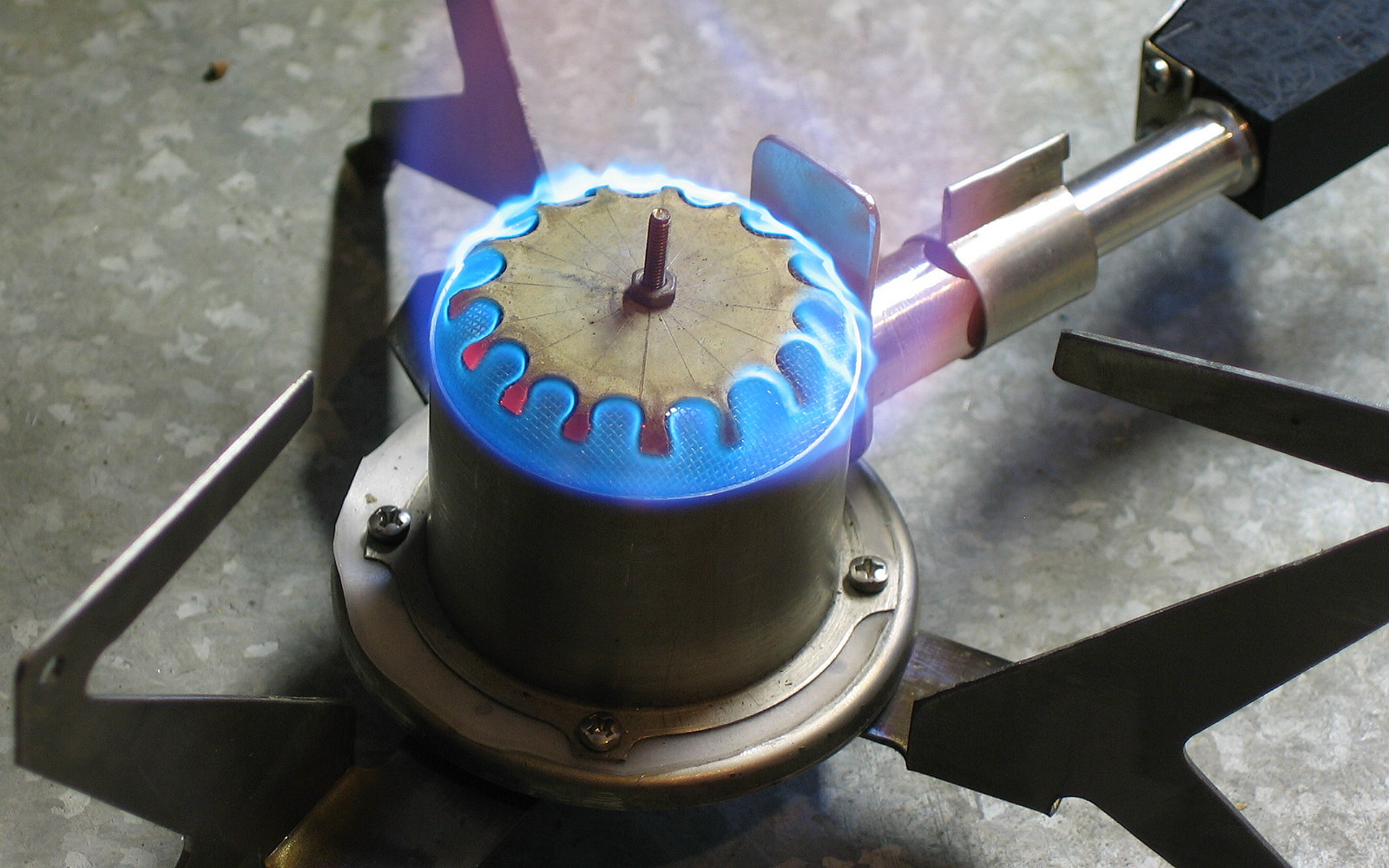
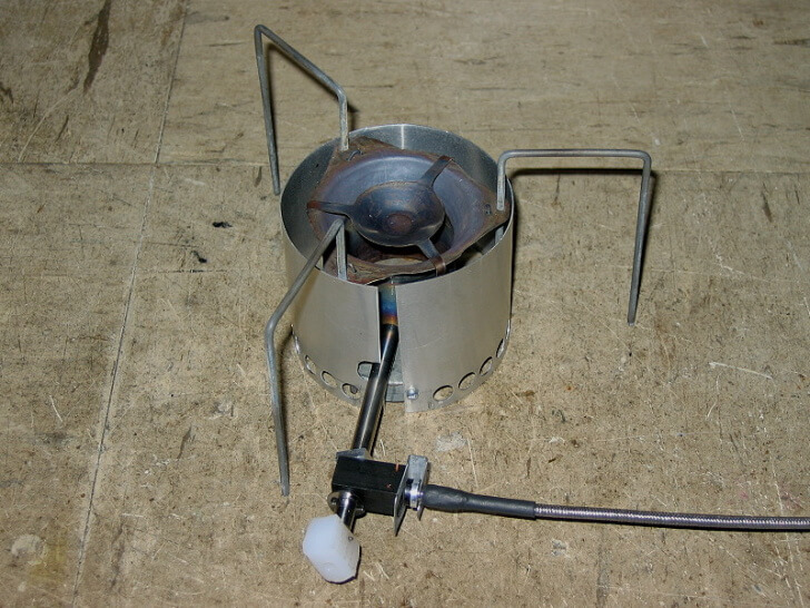
A second and the more subtle thing was that all of the above burners shown above bar one were “upright burners.” To be sure, the upright burner works very well, as everyone who has ever used one on top of a canister in fine weather can attest. They are relatively simple and can be very powerful (above 3 kW if you want). But there is another design possible for backpacking: the Vortex Burner. The classic example of this is the MSR XG-K white gas and kero stove. The physics of this design is different and interesting. In fact, I had built a couple of these, and I show one in the above picture in the bottom right-hand corner. Below another version is shown. (There is a third design, as epitomised in the MSR Reactor, but that design turns out to be a significant carbon monoxide hazard when used for backpacking. The burner is not good in a storm-bound tent, and not very reliable when the temperature crashes.)
An early MYOG Vortex Burner stove. It worked quite well.
Pot Supports
Even so, using a commercial burner head was not perfect. A complaint which did surface with the burner head I used was that the pot supports were a bit small and not suitable for big pots – unless you exercised a lot of care. That was true, although many of us manage just fine even with melting snow in a 1.6 quart (1.5 L) pot. Experience has shown that there are hazards with big pots: they tip over and produce excess downwards reflected radiation. But still, it was a small niggling hassle.
Leftover Stock
Somewhere along the line I had at some expense bought several meters of thin-wall titanium tubing, 1.5″ (38 mm) in diameter, for stove experiments and it was just sitting there on the shelf. It wouldn’t cost anything to experiment a bit more, would it? Especially as I had run completely out of burner heads for the V1 model and orders had also run out. And my CNC machine was sitting there looking hopeful. (Er – not true. I had to rebuild all the electronics when the gear put in by a third party started to fail).
Vortex Burners: The Whats and the Whys
What is a Vortex Burner, and how does it work? Why is it different? And why does it make such a loud noise? It turns out the noise is almost an intrinsic part of the fundamentals.
Comparing the insides of Upright and Vortex burners – (I am not an artist).
On the left, we have an upright burner. Gas (red) comes out the jet under pressure and whistles up the burner tube. The high speed of the gas going up the tube drags air (blue) in through the air holes. The fuel/air mix blends in the burner tube and the burner head and comes out the small holes in the burner head. (It’s a shade more complex than that, but no matter). The flame cannot get back inside the upright burner head because the holes are small – the same principle as used in the original Davy Safety Lantern (1815) for coal mines. In some designs, the face of the burner head reaches red heat, but very often it does not. I suggest, in fact, that it is better if the head does not glow; there is less risk of the flame getting inside. In one never-to-be-repeated Chinese copy of the MSR Whisperlite, the flames did get inside the burner head – via the air inlet. The burner head went bright red, and my hand went for the control valve. This was a very repeatable disaster due to a small Chinese change in the design for ease of assembly. They truly did not know what they were doing, which is scary stuff.
The Vortex Burner on the right starts with a jet at the bottom with the gas coming out of it, but then things change. Air is sucked in from the sides, or the base of the chamber and the flame starts to burn inside the burner chamber. Needless to say, the chamber gets extremely hot!
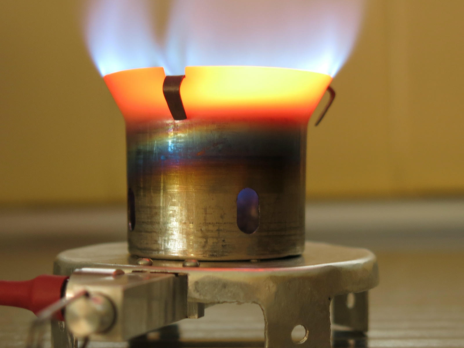
A glowing Vortex Burner.
Glowing bright red is normal. The explosion of volume due to the burning process pushes the flames and the burnt gases out of the burner chamber, to heat whatever is above. But in the process, the gases swirl around inside the chamber a bit, forming a sort of chaotic donut-shaped vortex. The very high speed of the swirling or random oscillation is what causes the “white noise” you hear from such a burner. Hence the name and the noise. Yeah, this is very different.
A quiet almost “Vortex” Burner with a cap on it (one of mine).
Can you quieten a Vortex Burner down? The answer is yes, in fact, you can, but it ceases to be a “Vortex” Burner when you do. You make up a burner head to fit over the top of the vortex chamber, with lots of holes, which converts it to a quiet upright burner. There are several ways to do it, and I have made and used such conversions. The first one I saw was created by a friend of mine long ago (30+ years ago?), but I don’t know from where he got the idea. The one here uses SS wire mesh instead of little holes in a plate, but that is just a small detail. You can buy such converters today from quietstove.com as well. Some of the burner heads in the second photo above would also come close to qualifying for this description.
A caution is in order if you wish to experiment. If you restrict the flow of fuel/air mix out the top too much, you may get some fuel/air mix coming out the air inlet holes lower down. This would, of course, instantly catch alight. That could be unfortunate, to say the least. Careful balancing is needed. Eh – what’s the matter with a little roar? It says dinner is on the way. My wife Sue listens for such things from where she snoozes at the back of the tent in the evening while I get dinner. It also provides extremely useful feedback to the cook while he is doing something else, like getting the food ready to go in the pot. If the roar changes, you check the stove immediately.
Early Vortex Burner Stove Designs
Early experimental Vortex Burner chamber designs.
It is tempting to jump straight to the finished article, but doing so would mean missing out on all the interesting deviations, fun, and failures I met along the way. It would also mean missing out on all the theory and practical results covering how and why a Vortex Burner works, and we wouldn’t want to leave you ignorant, would we? So here we have, in the roughly clockwise direction from the top left-hand corner and going into the middle, some of my early experiments. They all did work, at least “sort of,” although not well enough.
Two conical burners, the left one being spot welded titanium and the right one brazed gal steel. The steel is easy to form, but the zinc coating is a health hazard. The Ti was an utter pain to form.
Three Coke can windshields: two around titanium chambers with flared and flanged tops carrying holes used for holding pot support wires
A brazed brass attempt – very early and rather crude (bottom center)
Flared Ti tube with an external bottom rim, on a spun gal steel base (missing the splash plate)
Another flared Ti tube with lugs at the top for pot support wires, missing a splash plate.
A flared Ti tube with a splash plate done with Ti wire spot welded to the plate, on a Ti sheet base (middle)
Some of the splash plates are dish-shaped and are made from Titanium. Those took a lot of heat/thump cycles to get there. That little bit of metal cooled off so fast while I was getting it into the vice to squeeze or thump it. The flanged top rims on the chamber did take a fair bit of heat/thump too. Most of these chambers have the air inlet in the Ti tube, the same as on some commercial models. You can see from these how the idea of using Ti tube for the burner chamber developed.
Another early Vortex Stove design, also quite functional, with wide pots supports.
This is a somewhat more developed Vortex Burner stove, complete. The canister connector was a primitive version of my eventual solution for the Winter Stoves I sold, but the idea of mating with different canister designs was there already, as well as the safety shut-off valve at the canister. The idea of valving the gas flow very close to the jet rather than trying to micro-valve the liquid flow way back at the canister was also there. See the lumpy white control knob on the stove. The actual needle valve was inside the tubular body with the point of the needle and the valve seat near the jet, where the fuel was a gas. This “control valve on the gas flow” idea is one of the core features of my first winter stove design. This model even included wide pot supports and an integral windshield (not shown). The stove worked fine in the lab under gentle handling (OK, on the kitchen sink). I was not game to try it in the field on anything more than a day walk, for reasons which will quickly become clear.
I could see that this model had many defects in the design of the stove part, and it is instructive to go through them. Well, I think it is anyhow because they teach such a lot.
Weight: a bit too high, at 3.7 oz. (110 g)
Some of this was due to the use of 1/4″ (6.4 mm) ERW stainless steel (SS) tubing for the main inlet tube. I started with this because I had a lot of it. (I forget why).
Needle valve jamming
The needle valve was an inspired bit of .1 in. (2.4 mm) titanium wire with a machined tapered tip at the far end and a brass screw thread fitted onto it near the control knob at the near end. However, titanium and stainless steel have different coefficients of thermal expansion, and the difference goes in the wrong way. If I shut the needle valve off while the stove is hot and let it all cooldown, I can have immense trouble getting the valve open again. Due to the difference in the coefficients of thermal expansion, the stainless steel tube shrinks more than the Ti wire as it cools, so that the Ti needle always ended up jamming at the valve seat at the far end, under the jet. I could see damage and destruction coming.
Yes, I could replace the SS tube with titanium tube of the same size (I have some). Braze the SS tube to the brass jet fitting block, or there will be leaks, and you can’t (I can’t) readily braze titanium.
Mating the brass screw thread with the Ti wire
With some materials you would braze them together, but not with titanium. We have seen what happened when Jetboil tried to weld aluminum fins to titanium in some of their pots: there were too many weld failures. You can electron-beam weld Ti to Ti very nicely, but I didn’t have one of those toys lying around. A press-fit would only last so long, especially with the jamming. Glue was not an option at the potential temperatures; I was always allowing for >392 ºF (>200 ºC).
Making the heat exchanger work
The long SS tube forms a heat exchanger to vaporize the liquid fuel. The inside diameter (ID) of the SS tube was a bit over 13/64″ (5 mm) while the Ti wire was .1 in. (2.4 mm) outside diameter (OD). That left a huge gap, 3/64+ in. (1.3+ mm), between the two, and I found that the liquid fuel did not always fully vaporize as it traveled down the length. It often stayed in blobs, insulated from the hot tube by a thin layer of gas around it, and it sputtered out the jet still in liquid blobs. The solution (as used in my other Winter Stove), was to fill the bore up, so the fuel travels down it in a thin film. The Coleman Xtreme does this with that long thin brass rod which people puzzle over. I did this with a solid Teflon sleeve, but making those to a close tolerance was extremely difficult. Teflon is very soft and wobbles all over the place in the lathe. It is just as likely to spin around the Ti wire rather than being turned down. I didn’t want to use anything else because other materials were either too heavy (e.g., brass) or could melt when the stove got going for awhile.
Titanium wire legs welding
I did manage to do a bit of spot-welding of .1 in. (2.4) mm titanium wire to 2.4 mm titanium wire, as seen on the legs. However, I was not confident that the welds would last for years in the field. It’s tricky stuff to weld, and my welds can fail almost randomly. (I explain more about this below). A TIG or MIG welder with an Argon shield might have solved this (or that electron beam welder I wanted for Xmas), but I did not have either; the spot welder I used was another MYOG effort of mine.
Burner chamber top flare
In some early commercial Vortex Burner stoves (e.g., Optimus 8R), the burner chamber looked a bit like a parabolic cone. Made out of a bit of brass (or maybe stamped), it was heavy. After several attempts, I despaired of making that shape out of titanium and went instead for a parallel side (i.e., tubing) with a flared top. Making the flare was hard – the details will come later, but buying Ti tubing was easy from the right places on the web.
Burner chamber bottom rim
There has to be some way of rigidly connecting the burner chamber walls to the base. In the photo above there is an outwards turning rim, held down with some screws. Making this rim also presented real problems, as I will explain later. Curiously, it turned out that sealing this connection was not required. That was convenient.
Splash plate
The splash plate is the plate on top of the burner chamber. It consists of a disk with three support arms. (You could have more arms, but why?) It keeps the vortex of burning gas circulating briefly inside the burner chamber instead of shooting up into the sky, and is utterly and obviously essential. It is normally stamped out of sheet brass on commercial stoves, but it has been known for brass splash plates to erode (burn) away and fall off. This happened on one early Antarctic expedition, leaving the guys with no stove and no cooking (at sub-zero temperatures) until in desperation someone made a replacement out of a scrap of galvanised steel using little more than a rock. Desperate times, there! I wanted a titanium splash plate. I spent a lot of time trying to get good spot welds between the .06 in. (1.6 mm) wire and the .02 in. (0.55 mm) sheet titanium but they were just not reliable enough and not manufacturable. I also tried thin strips of Ti sheet instead of wire, but the welds were still unreliable. More details (much more) on splash plates later.
Splash plate contour
Most brass splash plates are dished in the middle, although manufacturers don’t tell us why. I guessed it was to aid in shaping the vortex flow. The dished shape is easy to get with brass (kerthump), but it seemed almost impossible with Ti 6Al-4V alloy sheet in the early days. That alloy does not bend cold, and the tiny thermal mass meant it cooled faster than I could process it, and I did not want to make a hot press for this! So it seemed I would have to use a flat splash plate, and make it work.
Plastic hose/stove connection
You can see the white connector with the blue marker pen on it, connecting the hose to the stove. That style of connection had several problems. O-ring sealing inside between the plastic connector body and the SS tubing was finicky. Tolerances had to be tight, and I had to prevent the O-rings from flying out under pressure. Anchoring the hose into the connector was also tricky, with more O-ring problems due to the wire catch. The wire catch was not super-reliable either, and could damage the O-ring. Surprisingly, the use of plastic here was not a problem; I was using PEEK for this, and that plastic is usable to 482 °F (250 °C) long-term and 590 °F (310 °C) short-term. It’s not cheap, though.
Non-optimised design
Need I add here that none of the features in any of the above models was anything like “optimised?” That stage always comes a lot later.
So in the short term, I focused on the upright burner model instead and got that Winter Stove V1 to market. But this Vortex Burner Stove did work moderately well, all the same, so once I had sold all the upright burner stoves I had made, my thoughts turned back to that expensive Ti tubing I had sitting on the shelf.
Technical Note on Welding Titanium
I am throwing this in here just in case someone asks why is it so hard to weld titanium. You can easily solder metals like copper and silver together, and it is not hard to solder or braze brass, and with a little bit more heat you can readily braze or weld steel. All you need for those metals is a flux which can displace any surface oxide layer so the molten filler metal can merge with the clean base metal.
The problem with titanium is that it is very reactive, and an oxide layer covers any new surface. Ordinary fluxes cannot displace the titanium oxide layer; it is too “stable” and tenacious. So when you try to join two bits of titanium together, you very often end up with a very weak oxide layer between the different bits of metal. Sometimes my spot welds displaced the oxide layer to give a strong metal joint, and sometimes they didn’t. Quite often what I got was more of a Lego-style joint, tiny bits interlocking through an oxide layer.
Critical Preliminary Experiments
It seemed to me that I had enough from the early experiments to say that a Vortex Burner Stove should be possible. The Canister Connector and Hose were known territory from the V1 stove. There needs to be a “stove body,” but again the work on making the V1 stove suggested that this could be done without too many problems. I assumed that the needle valve would be equally simple, which was not quite true. However, lots of people make needle valves, so I figured it should be possible. The big unknown at this stage was the Burner Chamber and the bit on top called the Splash Plate. I wanted to use the Ti tubing for the Chamber and Ti sheet for the Splash Plate. Could I make these in a realistic (repeatable, manufacturable) manner? At the start, that seemed to be the crucial question.
Bending Titanium, hot and cold.
Making a viable titanium burner chamber was for a long while a major stumbling block. The Titanium sheet I have is the very popular and very strong 6Al-4V alloy, which is impossible to bend cold. When you finally get it to bend (it takes a lot of force), it usually cracks unless the radius of the bend is large. But this 6Al-4V alloy is what they call “super-plastic.” It can bend very well once it is up to red heat. In the photo here, the sample on the left was bent at red heat, and is fine; the sample at the right was bent cold, and it cracked. You can see the crack. I will add that bending “pure” titanium, often called CP (for Commercially Pure), is much easier, but CP is nowhere near as strong as 6Al-4V.
Fortunately, the Titanium tubing I have is not the 6Al-4V alloy. Instead, it is the 3Al-2V alloy, and this sort of tubing often uses that alloy. Since the tubing I have is rolled up and welded (ERW) it can obviously bend a bit. Some “distortion” of this alloy or tubing was, therefore, hopefully, possible. I had several ways to do this.
Spinning lathe: hydraulic force replaces screw threads (old dealer “For Sale” photo from the web).
The most obvious way was to spin the tube on a mandrel in the lathe and to shape it using “spinning technology.” After all, they make all sorts of spun aluminum shapes this way. But I found that Ti 3Al-2V alloy was a lot harder than any 5000-series aluminum. I could shape it in the lathe using a roller bearing as the “pusher,” but after one or two unsuccessful attempts it was obvious that the forces involved would soon destroy the cross-slide on my little lathe. The lengthwise feed along the lathe bed was also going to suffer. It turns out spinning lathes are built “slightly” differently, at least ten times heavier and stronger! Some of them are massive: a lot bigger than my lathe! They don’t use screw threads for movement; they use hydraulic rams, and that is still just for aluminum.
Manual flaring – inelegant (posed photo, no flame).
The next way was to make up a female mold – essentially a tapered external clamp. Put this around the tube and hammer the tubing out against this mold. I made one up out of steel, and it worked, but the result was a bit erratic and a lot of work. Heat from a propane torch helped (a lot), but holding a propane torch in one hand and doing controlled pounding with a hammer in the other hand, while holding the clamp in the vice was “a bit tricky.” Samples are shown here and in previous photos. The results were rough and inelegant, and also not manufacturable in volume.
Commercial copper flaring tool (one of many product photos on the web).
My next idea was to make a matching male mold to go inside the tubing while the female mold was on the outside, and to squeeze the two together, very much like the flaring tool used on copper tubing by plumbers. This was a great idea, but way beyond what force my drill press could do. You might note that typical plumbers’ flaring tools are for soft copper and for up to about 5/8″ (15 mm) diameter while the tubing I am using is titanium and 1.5″ (38 mm). Not to mention the huge mechanical advantage you get with the fine screw thread on the tool shown here. I tried putting the lot in my cast iron 4″ (100 mm) vice and cranking the handle. That worked, and it produced a satisfactory flare, but it was leaning a bit hard on the poor old vice. Life prediction for the vice if used for that was not encouraging (and good cast iron vices are expensive).
Then there was the problem of the other end of the burner chamber. I had managed to flare the bottom edge out with a hammer and heat. I used an internal mold to hold the inside shape and an external ring clamp to lock the tube on the internal mold. The result was a bit lumpy, and I had to completely disassemble the clamp to get the burner chamber out. Fortunately, that ring clamp had been made to come apart like that.
Burner chamber, diagrammatic.
So when I restarted, I tried making the bottom rim go inwards, and this was an improvement. I could now just slide both parts of the mold off the tube. The external part of the mold slid down past the inwards-turning rim at the bottom, while the internal part of the mold came out upwards past the outwards flare at the top. A little care was needed when hammering the bottom rim inwards to avoid having the outside of the rim bulge slightly outwards. This happens as hammering the rim inwards compresses the titanium there, and that pushes outwards on the tube just at the bend. Any bulge would prevent me from sliding the external mold off the first time. (And yes, it does bulge outwards given half a chance). I could do all that, but I had to flatten the rim against the inside part of the mold with a bit of hard steel and a hammer, and that made dents on the surface of the softer steel mold. (Did I just say mild steel was soft? Yep).
However, despite all the problems, making a titanium burner chamber was possible. And so, the project started.
Summary so far
The early photos show some of the bigger problems I met along the way. I didn’t have simple solutions for them at the time, so I let the ideas sit for a while and got on with developing, making and selling the upright burner V1 stove for a couple of years. That was very successful, and I have sold over 110 of them. (I don’t have any left for sale, but I could make more if needed). A recent revival of my experiments suggested that the idea of an MYOG Vortex Burner Stove was not impossible.
Finding that I could (probably) make a satisfactory vortex burner chamber shape out of my Ti tubing (somehow) was the necessary boost to my enthusiasm. All I had to do was to solve a few more minor problems (he says). So in the next few parts of this series, I will look at these “minor problems.”
The Snuffle Flask is a lightweight fuel dispenser that works with any alcohol stove. Learn how to make one from items in your home.
A Very Lightweight, Fuel-efficient, No Fuss, No Fumbling Alcohol Stove System
Introduction: Filling a Lambda Stove Using the Snuffle Flask
The Lambda stove is my personal MYOG Alcohol Stove that I plan on writing a future article about. This article will cover the Snuffle Flask an alcohol fuel dispenser than can be used with any alcohol stove. A fuel efficient cooking system consists of a stove, the environment, one’s fuel supply, the ability to measure, a lighter/starter, a pot, a pot stand, and a windshield. Each item has to work together properly to create an efficient system.
The Snuffle Flask is a fuel bottle with an integrated fuel measuring and dispensing system. It is a simple and reliable way to fill the exact amount of alcohol needed for any alcohol stove without utilizing multiple devices.
Disclaimer
This project is not a beginner’s project. You will be working with very sharp tools. Be sure you have the necessary experience to work safely with the tools you will be using. And: alcohol fuel burns. Use common sense and don’t burn yourself or anything else.
Measuring fuel without the Snuffle Flask
Everyone who has operated alcohol stoves knows that accurately measuring the amount of alcohol going in the stove is challenging. You are supposed to use a small measuring cup, but if you are tired and hungry, filling the necessary amount of alcohol into the cup is difficult. Trying to get a decent read on the amount of alcohol poured when it’s dark is difficult also. It is difficult to fill the stove without spilling, to keep track of the fuel bottle cap, and to keep the fuel bottle from tipping over. After all, you are in the backcountry, far from any picnic table. Also, dexterity and intellectual abilities tend to deteriorate rapidly once a person gets tired and hungry.
The video clips on youtube make operating an alcohol stove look easy. Alcohol stoves can be quite sensitive to their environment. The usual “penny stove” will die in anything but warm and sunny conditions. I have once used nearly 10.1 oz. (300ml) of alcohol to cook 33.8 oz. (1 liter) of soup. I missed a warm meal once because of this. Here is my solution to provide a no fuss, no fumble, no spilling, and easy to operate system that works under most conditions encountered on backpacking trips. The system described can even be operated wearing gloves.
The core element of the system is the fuel bottle. For one to two person use, a fuel bottle of 8.5 oz. (250ml) to 11.8 oz. (350ml) is fine (for me) and will work for a couple of meals. Actually, one single 11.8 oz. (350ml) bottle of fuel (yellow “Heet”) was more than plenty for a 5-day/4-night summer trip my wife and I took in the Sierra Nevada. We were at 10’000 ft+ (3048 m+) elevation and had dried meals to rehydrate and no restrictions on the amount of tea, coffee, soup, etc. For 2 to 3 people or for longer trips, I may take a 16.9 oz. (500ml) bottle, or I may prefer to refill my smaller bottle every once in a while. Larger groups will carry more than one system, especially when will have to melt snow to get their water.
The diameter of the bottle cap matters when wearing gloves. There are mainly three sizes of bottle cap diameters on the most popular PET bottles. Water or pop/soda bottles usually come with cap diameters of 1.1 in. (29mm) or 1.3 in. (32mm). You will also find the lightest bottles in this group. You might feel they are a bit on the flimsy side for a fuel bottle. I believe, however, that they are okay as I integrate them into my system and carry them in my backpack, protected by the windshield and another (flimsy) PET-container. Lightweight gear is designed for use, not for abuse. If you want to abuse your gear, go to the army surplus store. The bottles containing fruit juices and smoothies come with 1.6 in. (40mm) caps and tend to be a bit sturdier. The 1.6 in. (40mm) caps are nice to operate with your gloves on, too.
Developing the Fueling System: The Stages of Error
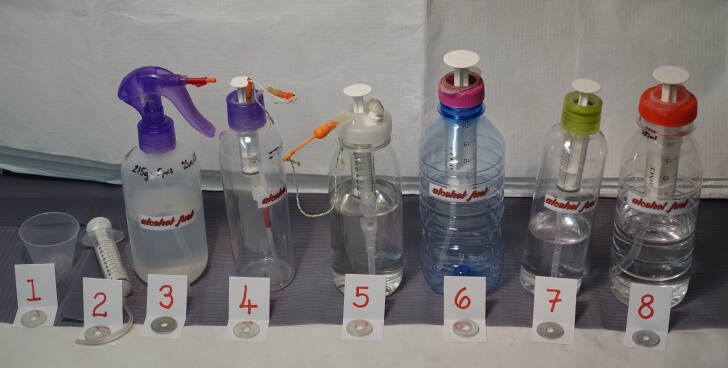
The stages of error.
The usual measuring cup. There is no easy read of the amount measured.
This was my system during the 2015 season. It consisted of a 10ml syringe fitted with a short length of flexible fuel tubing from the RC model hobby shop. It is easy to read, but the fuel cap has to be taken off and left unattended during operation. The flexible tubing can direct the alcohol into the wrong compartment of the stove if you are using a Trail Designs 10-12 stove, for example. A piece of stiff tubing is a wiser choice.
This model is an air freshener pump with a drilled out nozzle fitted to your fuel bottle. Needs two hundred (sic!) pump strokes to get out .7 oz. (20ml) of alcohol. Not trail worthy!
This was my first attempt with a built-in .2 oz. (5ml) syringe and also with two valves from a foot freshener spray. A real pump puts out .2 oz. (5ml) of alcohol on each stroke. Aptly called the “Snuffle Flask” by my elder son, the flask needs an air bleed device to let in some air, so there are three holes in your bottle cap. The holes pose sealing issues. The two caps used as an air bleeding device and fuel spout are prone to leakage, too.
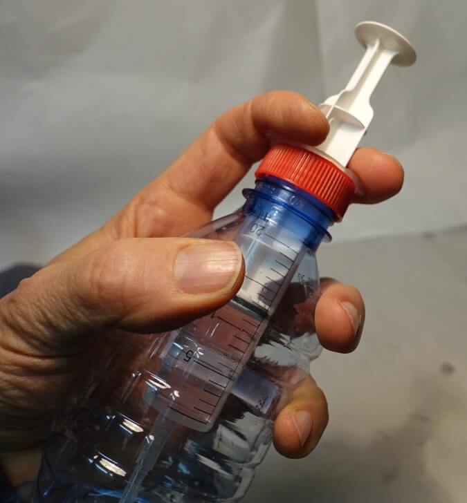
The photo shows the enhanced Snuffle Flask with an air bleed screw and larger diameter bottle cap to accept a 10ml syringe. Handling all three devices on the cap at the same time is still a bit fiddly (open air bleed screw, uncap fuel outlet, pump the necessary amount, close all openings again). At least, there are no items of which to keep track. Everything is attached to the fuel bottle. There are still three holes in the bottle cap that are prone to leakage. The air bleed is a screw that is a bit tricky to manufacture. During a family discussion, I proposed to skip the air bleed screw and replace its function by merely untightening the bottle cap. Whereupon, my elder son proposed to leave out everything except the syringe mounted to the cap – bingo!
This photo depicts the first versions of the final design of Snuffle Flask. Leakage remained a problem, as gluing a syringe to a bottle cap is problematic, i.e. the soapy type of plastic used for bottle caps tends to split from any type glue.
This is the first coupling-nut system. This system presses everything down on a sealing ring. It is fuel tight and trail-worthy.
Same as #6.
Fuel Bottle Design and Construction of the Snuffle Flask
I will show you three fuel bottles:
The “Simple-simple Flask” may leak unless you are proficient with hot glue or find a lucky combination of a syringe and bottle cap (see pics 02, 45 and 46);
The “Screw-on cap Flask” is the “normal” choice for anyone. It uses a wide cap (see pic 51, the right flask); and
The “Coupling-nut Flask,” is probably the safest example, but a bit tricky to make (see pics 51, left flask, and pic 65). Choose a bottle with a large cap if you intend to operate it wearing gloves.
Materials Required for All Three Bottles
The materials you will need.
This construction requires a wide-mouthed, clear PET bottle, preferably with 1.6 in. (40mm) or 1.3 in. (32mm) outer cap diameter, 8.5 oz. (250ml) to 11.8 oz. (350ml). I do not like colored bottles; I want to see what’s happening inside. Get a couple of different drinks, smoothies and the like; drink them, clean the bottles, and have a close look at their cap. The caps have an inner rim to fit the inside of the bottleneck. Keep off bottles without this, like the ones with an additional sealing foil on the mouth when you take off the cap. These caps will not make a reliably tight seal. Have several caps on hand because you may not succeed with your first cuts into the cap.
You’ll need 20ml or 10ml disposable syringes without needles. Get half a dozen; both sizes are very reasonably priced at your drugstore. Don’t expect your first try to be entirely successful. The 10ml requires more pumping on the trail while the 20ml is a harder fit but more convenient to use.
You’ll also want silicone rubber cement. I use a heat resistant glue which I can also use on my stoves. The shelf life of this sealant is limited.
Hot glue sticks.
Two little self-tapping screws about 13/64 in. (5mm) long, about 5/64 in. (2mm) outer diameter, 5/34 in. (4mm) head width, or, two equally small metal screws with nuts. If you can fit a 10ml syringe, you may get away with slightly larger screws.
A short end of plastic tubing measuring about 5/64 in. (2mm) to 1/8 in. (3mm) in diameter (derived from an old air freshener bottle, for example, any other pump-spray, or clear pushrod housing from the RC-model hobby shop).
Tools Needed
Some of the tools you will need.
X-Acto type knife with a few pointed blades (#1 on pic)
Hot glue pistol (glue gun) with glue sticks
Razor saw, small hacksaw or Dremel type table saw
Circular cutter. In order to make a cutter (#2 on pic) yourself you will need:
A small hardwood block 1 1/32 in. x 19/32 in. x 25/64 in. (50mm x 15mm x 10mm, roughly)
An X-Acto type blade
Three small self-tapping screws
One sturdy pin of .1 in. (1.5mm) diameter (the circular cutters available in the handicraft section of your department store or hardware store tend to be too flimsy to do our job)
Hand drill or drill press with .1 in. (1.5mm) and .1 in. (2mm) bits (#3 on pic.)
Small metal ruler 7.9 in. (200mm) long. The one shown is flexible and has a thickness of exactly .02 in. (0.4mm); #4 on pic
A sliding caliper is an asset, but this is a pricey precision tool (keep your hands off cheapos, they are not accurate enough – buying cheap means buying twice!)
220 grit sandpaper
Sharpie type pen
Hairdryer
Round awl or prick
Candle or lighter
Medium sized half round file
Small half round file (“needle-file” type)
Standard pliers
Small wire cutter
Construction Steps
Measure the diameter of your syringe (a caliper comes in handy). Wrap a strip of paper around your syringe and mark where the rest of the strip reaches its beginning. Make sure the strip is wound tightly. Using a pen to mark makes a more precise line than a pencil.
Measure the diameter of your syringe if you do not own a sliding caliper.
Unwrap, measure the length of the strip up to the mark, divide by 3.141 (π). This is the diameter of your syringe. The 20ml Once brand measures .9 in. (23.0mm), the 10ml is .7 in. (17.4mm).
Measuring the length of the circumference. Starting in on the ruler gives you a better reading than beginning at the zero end.
The Simple-simple Flask
If you are not comfortable with the knife, this one is for you. Take a “sports-style” bottle cap. As these bottle caps are somewhat conical, you will find the proper diameter for your syringe somewhere down from the tip (have a few caps ready).
Fitting a syringe to a sports style cap – I don’t like this individual make of caps, as a tight fit is missing and the cap covers part of the scale.
Now saw slices off the tip carefully with your razor saw until the opening is just big enough to accept your syringe.
The process of slicing and fitting with a sports style cap.
You will probably have to carefully and slowly take a burr off the outer side of the cap.
How to remove a burr.
Now you should have a perfect, somewhat tight fit. If the fit is perfectly tight, don’t test over and over. You will scrape the scale off your syringe, so confine your testing to the lowest end of your syringe.
Sand the cap inside and outside with the 220 grit sandpaper. Also, sand the handles and upper cylinder of your syringe. Then clean with alcohol. Put the syringe into the cap. Heat up your glue gun. Let it run really hot. You want the glue to flow. Heat the bottle cap and syringe with your hairdryer thoroughly and as hot as you can stand with your fingers. Any more might start melting the cap or the syringe. You do want to avoid this, but you want a warm cap to keep the hot glue flowing and bonding as well as possible.
This is really important. I had a few caps split from the hot glue at first. I noticed the hot glue partly rolled off the caps. This is when I started heating caps and syringe cylinder prior to gluing. I still would not entirely trust the bond. To find out, I made a new cap for testing. I sanded the cap and syringe as described, cleaned them with alcohol, and then heated everything thoroughly with the hairdryer. Then I quickly glued everything with hot glue. Some parts of the cap which didn’t bond well received an after-treatment with the lighter (careful!) Then I threw the cap into the deep freezer (0°F, or -18°C) overnight. The next morning, I took it out and quickly tried to get the glue to split from the cap, yanking the syringe back and forth. Nothing happened, no splitting. After all the abuse, the system was as airtight as before. So proper heating is paramount for a good bond and seal.
Caveat: Unless you land a “lucky punch,” the setup relies completely on the hot glue. If you apply moderate force or continued operation, the device may start to leak, as there is no mechanical tie between the bottle cap and the syringe. If you want to rely on the hot glue alone, refine your gluing techniques and test the arrangement thoroughly before hitting the trail.
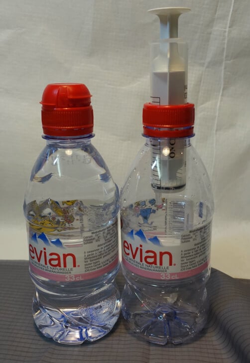
You may, however, land a lucky punch by combining a 20ml syringe with a 1.3 in. (32mm) sports-style cap. Cut the conical tip off a Vittel sports cap leaving a screw-on ring that can just be forced over the cylinder of the syringe to make an almost alcohol-proof seal. A portion of the inner rim of the Vittel cap was just the diameter of my syringe.
A perfect, very tight fit. (The photo shows the syringe placed incorrectly).The “lucky punch” seen from inside the bottle.
This made a far better seal than any (tight) hole cut into a larger cap. Without any sealing, there was just a little dripping.
Almost fuel-proof without any sealant.
After applying some hot glue, the system was airtight. Because there is a pretty good connection between the cap and the syringe, this system will stay sufficiently tight. It can easily be resealed with a lighter should it leak. Rinse thoroughly with water before attempting to heat the hot glue seal with a lighter or you will end up hospitalized with severe burns. Any residue of alcohol left in the system will light up and burn. Also, take out the plunger first; it does not stand any heat.
It may pay off to go through a couple of differently capped bottles available in your supermarket.
Amazingly “lucky punch” with the Evian 11.2 oz. (330ml) sports bottle. This one, needs solid gluing, however.
You can also make this version with regular caps, but you will have to cut a circular hole into the bottle cap with the cutter you make for the other versions. The small pop bottle caps of 1 9/64 in. (29mm) diameter will only accept a 10ml syringe, however, as the bottleneck is too narrow to accept the 20ml one.
Other Simple-simple examples.
The Screw-on “Normal” version
This version should be as bomb-proof as ultralight gear. The syringe screws to the cap, is sealed with a silicone sealant, and is doubly sealed with hot glue.
First make your circular cutter. Cut about 1 1/32 in. (50mm) off a hardwood strip cross section of about 25/32 in. (20mm) x 19/32 in. (15mm). Use hardwood like beech or oak. Any softwood like spruce or fir will fail. Screw an X-Acto type blade to one end by placing two screws at the back, one over the sharp side of the blade. Measure exactly half the diameter minus half a millimeter of the diameter of the cylinder of the syringe you are using to the X-Acto type blade towards the center of the hardwood block. Drill a 1/16 in. (1.5mm) hole here to house your sturdy 1/16 in. (1.5mm) pin. Just make it tight and snug. You can drill other holes to fit other size syringes, or use this for other circular cutting needs and the stove.
Your sturdy self-made circular cutter.
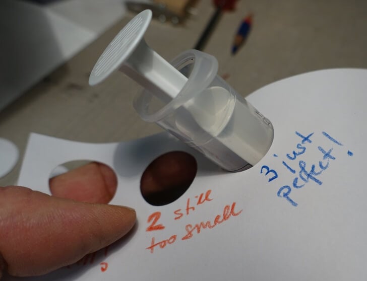
Test your cutter on a piece of drawing paper and check whether the syringe fits. If it fits, the diameter of your cutter is probably too wide. Make another cutter.
Testing your cutter for proper diameter.
If the hole (hopefully) is a tad too small, insert shims between the hardwood block and the blade. I added three layers of masking tape and one layer of heavy (200g/m2) drawing paper.
How to shim your blade to enlarge slightly the diameter of a cut.
Now the syringe just fits through the hole.
Testing the cutter to fit the syringe.
With the 20ml syringe, it gets tight between the inner rim of your bottle cap and the syringe. I gain space by filing some material off the cylinder of the syringe, right below the handles.
Gaining some space for the screw heads.
The syringes used have a wall thickness of exactly 3/64 in. (1.0mm). Filing away half a millimeter on both sides poses no stability or leakage issues. If using a 10ml syringe, you can omit this step.
Look at your bottle cap. The inner rim makes a seal like a plug and has to be left intact by all means. Make a paper disc fitting exactly inside the inner rim of your bottle cap. Draw a line across the center of the disc, and mark the diameter of your syringe on the line. You see the diameter of my 20ml syringe marked here.
Making a pattern for the holes to drill.
The self-tapping screws barely fit between the cylinder of the syringe and the inner rim of the bottle cap. I measured exactly 5/64 in. (2mm) from the edge towards the center (half the diameter of the head of my self-tapping screws) and marked with my sturdy pin on the bottle cap.
Marking the position of the screws.
If you go with the 10ml syringe, just divide the distance between inner rim and cylinder of your syringe into two equal parts. That will help you decide what size screws and washers to select.
To cut the hole in the bottle cap for the syringe, remove the drawing paper shim from your circular cutter. I found the cutter to make too large a hole. Due to the flexibility of the plastic, the hole must be cut a tad smaller than on (stiff) paper. Put the cap back on the bottle to get a good grip on it and to prevent the cap from distorting. The caps usually have their center marked. Prick the pin of your circular cutter precisely in this mark and draw the circle. It is important not to apply force. Just a slight but precise scar on the cap is intended. Then go on, deepen the scar gradually.
How to properly cut a cap: deepen the scar gradually.Cap cut to accept your syringe.
When you are through, insert your syringe to check the fit. It should be a snug fit, no “air” between the syringe and the cap, but no forceful cap distortion either. If the cap slides down the syringe by itself, the hole is too wide. Just one shim of 200g/m2 drawing paper made the difference between the loose fit and the snug fit in the picture.
#1 slides down because it’s too wide; #2 stays put perfectly.
If the hole is too large, you may not get a tight seal. If the hole is too tight, you may open it up with sandpaper wrapped around a dowel. Go easy, a little at a time, and check with the syringe often.
Once you have your cap ready, drill two 5/64 in. (2 mm) holes at the marks near the rim.
Drilling the screw holes.
Take the burrs off with your knife.
Cutting away the burrs.
Your self-tapping screws should just fit through the holes. They touch. Do not distort the inner rim of the cap. Put the syringe in all the way. Center the handles of the syringe over the small holes in the cap and mark with Sharpie type of pen.
Mark the position of the screws on the handles of your syringe.
Turn the cap around and give the handles of the syringe a center punch with your awl exactly on top of the screw holes marking where to center your drill bit.
Ready for center punching.
Also, mark the side of one handle on the cap and the corresponding handle of the syringe. Even if you work very precisely, it will matter which way you insert the syringe.
Red dots mark which way the syringe is supposed to be mounted.
Take the syringe out and drill holes into the handles at the markings. The holes should be about the diameter of the core (not the threads) of your self-tapping screws: The screw threads in the picture have a 5/64 in. (2mm) diameter and the screw core has about a 19/32 in. (15mm) diameter. I drilled 1/16 in. (1.5mm) holes in the handles. Drilling your holes too small will split the handles of the syringe. If drilled too large, the screws will not fasten the handles.
Drilling the screw holes.
Assemble the flask. If needed, the screws can be forced a little to find the holes, but be sure not to distort or damage the inner rim of your bottle cap.
Helping the screws to find the holes in the handles.
Check for fit.
Testing the assembly.
Take it apart again.
If you own a drill press and a conical cutter head, you can cut the hole for the syringe the way shown in the picture.
An alternate method for cutting the hole into a bottle cap.
The drilling is easy when you are near the intended diameter. The photo shows the 10ml syringe at 11/16 in. (17.4m) diameter and my conical cutter only goes up to 25/32 in. (20mm).
Now you have both examples assembled and ready for sealing. Mounting the 10ml syringe is clearly is easier than the 20ml.
View of the caps from the underside as they are ready for sealing.
If you care and have the equipment, shorten your screws now. Once the screws have tapped their threads into the handles, they can be screwed into those threads without a pointed end. If you omit this step, you will have to cover the protruding screws well with hot glue. Do not attempt to grind the screws down after they are mounted to the cap. The screws will get hot, melt the plastic and tear out. The system will be damaged beyond repair.
Shortening the hard screws to length.
Roughen the inside and outside of the cap, the underside of the handles of the syringe, and the top of the syringe cylinder near the handles with 220 grit sandpaper. Clean the areas thoroughly with alcohol. Apply silicone sealant sparingly to the underside of the syringe handle and the underside of the upper rim of the syringe. Apply additional sealant to the inner side of the bottle cap around the two small holes for the self-tapping screws.
Applying some silicone sealant.
Insert the syringe and screw it to the bottle cap. Don’t over-tighten the screws; just snug is enough. You are working with flimsy plastics. Scrape away any excess silicone. You only want a seal between the bottle cap and the syringe, not anything else. The silicone also does not stick to the plastic. It only forms a custom-fitted sealing ring, which has to held in place by other means. Put the project aside and let the silicone cure thoroughly, at least two days because silicone usually hardens slowly with moisture removed from the ambient air. It is not a good idea to remove any silicone smears and surplus later; you run the risk of pulling the silicone out of the fit between cap and syringe.
Systems mounted with silicone sealer.
Clean the inside and outside of the cap with alcohol again. Heat the assembly with your hairdryer (see the Simple-simple version for the why) and seal thoroughly with hot glue. Apply hot glue to the top and inside of the warm bottle cap. Don’t overdo it; you will only add weight. Sealing around both the inside and the outside will do. Cover the screws well to avoid getting hurt during operation of the flask. Let the hot glue set well, leave it alone for about a quarter hour.
The hot glue seals: If you prefer, replace the self-tapping screws with small brass metal screws (M2) and cut them to length. You can even cut threads into the handles of the syringe to forgo the nuts if you have the equipment. The 10ml syringe will also accept larger screws (M3). This size is even available in nylon (RC model hobby shop).
Systems: If you want, carefully cut away any excess hot glue, just chip off small flakes of glue if necessary. If applying force has the glue split from the cap, your gluing needs refinement. You need to work fast as long as the cap and the syringe are hot. You can try to reseal by heating the cap and syringe with a lighter, but take out the plunger of the syringe first, it does not stand any heat. Do not do that once you have used the flask with alcohol. Also, keep the flame well clear of the rim of the bottle cap, as the rim will melt away if overheated.
The Coupling-nut Flask:
Coupling-nut Flask ready to be screwed down to the flask.
If you are adroit with the circular cutter and X-Acto type knife, there is a quick and elegant alternative. Instead of screwing the handles of your syringe to the bottle cap, just stack a seal, a plug, and the syringe and screw the layers to your flask with a coupling-nut. A Coupling-nut system can be made from another bottle cap and is shown here with a water bottle and its 1 17/64 in. (32mm) diameter cap. One of the bottle caps is cut down to a ring (#2 in the pic), the other one to a coupling-nut (#3 in the pic.).
Bottle caps #1, cut into a ring,#2, and a coupling-nut, #3.
This flask is one for those who take a 10ml syringe. The flask with the greenish cap is such a system too (see #7 in the very first picture).
First, drill another pin hole into your circular cutter. You can use it to cut away everything off one bottle cap just outside the outer diameter of the bottle mouth. Go easy, you will need to do a second cut and do not want a loose center hole in the cap on which you are working. Then cut the hole for the syringe. The resulting ring, together with your syringe will form a plug to fit the mouth of your bottle (see #2 in the picture).
Slide the ring over your syringe and, with a small wire cutter, clip away the part of the handles which protrude over the ring. Clip several small flakes to prevent the syringe from splitting. File and sand without damaging the ring. Take the ring off. Sand the upper part of the syringe with 220 grit sandpaper. Clean the ring and syringe with alcohol. Heat with a hair dryer and glue the ring to the top of the syringe with hot glue.
Hot gluing the sealing ring to your syringe.
Work quickly on a well-heated syringe to push the ring all the way up into the still hot and running glue. Do not touch the (hot!) glue; just push the ring.
Pushing the ring up into the hot glue.
Put some hot glue on top of the ring between the handles of the syringe. You want to have an even top rim of your plug consisting of a ring and syringe. The coupling-nut will press down around the rim, not just on the handles of the syringe. Even out the top rim of your system plug.
When the glue has cooled and hardened completely (wait), put the plug on your flask and chip off any excess glue, making an even outer and top rim of the plug.
Make sure the rim is evened out with hot glue.
Then you make the coupling-nut. Create a second circular cutter to cut a hole exactly the diameter of the plunger of the syringe.
Cutting a coupling-nut.
Keep the required hole small; the smaller the better. (You may use a suitable conical cutter as in the example shown above). The coupling-nut will be forced over the head of the plunger, which is a bit wider than the shaft. This configuration prevents the coupling-nut from getting lost on the trail. After cutting the hole, you have to remove the inner rim of the cap.
Removing the inner rim of the cap to be transformed into a coupling-nut.
Now you can assemble your system and check for fit.
Assembling the Coupling-nut Flask.
Finishing all versions:
Measure the length of the tubing, bottle, plug/syringe system, and your awl.
Materials and tools needed for finishing.
Heat the awl with a candle or lighter and push the tubing over the hot awl to widen one end.
Widening the tube to fit over the nozzle.
Repeat until the tubing fits snugly over the nozzle of the syringe.
Fitting the tube.
Do not apply too much force in order not to avoid tearing the tube. Torn tubing will leak when you try to fill your stove. If it does not work, your awl is not hot enough.
Carefully heat the tubing a little below the syringe to give it a gentle permanent curve that will direct the tube to the point where the wall and bottom of your flask meet. Hold the system alongside your flask to estimate and cut the excess tube at a 45° angle.
How to cut your tubing to length.
Careful; leave it a bit too long. You can always cut again. Screw the syringe/cap system on tight and check for length. Repeat the cutting process until snug.
The Proper length of fuel tubing.
Give the lower end of the tubing a 45° cut on the opposite side to prevent the tube from sucking to the wall or the bottom of the flask during operation.
End of the tube cut for reliable operation.
I had several tubes split after a few days. I suspect I forced those tubes a little bit too much when mounting them to the syringe. After some use, you should see to keep the tubing well above any of the ribs often found as reinforcements on the bottom of the flasks. Forcing the tube over these bumps everytime you close the flask stresses the joint at the syringe and may split your tube.
Tube fails if overly forced.
To avoid this problem, you can couple the stiff tubing with a short length of a (flexible) silicone tube running to the syringe. A 19/32 in. (15mm) length and 1/8 in. (3mm) inner / 13/64 in. (5mm) outer diameter piece of silicone tubing does the job nicely. Use fuel tubing from RC-model hobby shop. Make sure you push the nozzle of the syringe and the stiff tubing deeply into the silicone tubing so that they meet. You do not want the tube to flex. It is supposed to rest securely in the bend between the bottom and the wall of your flask, so that you can “snuffle” up the last drop of your fuel.
Alternate fitting of the fuel tube.
Congratulations, you are done! Four different snuffle flasks with their respective weights are shown in the picture. I think around 30g (1.1 oz.) for such a system is appropriate. The Swiss precision spring scale shown in the picture measured all the weights for the project. It’s not just a “guesstimator,” it’s a pretty pricey tool of precision. For gram weenies, you could save another .2 oz. (7g) on the 1 oz. (29g) flask if you use a 10ml syringe instead of a 20ml.
Detail: the Coupling-nut Flask on the left, the “normal” system on the right.
Now fill your Snuffle Flask with alcohol, taking the volume of the syringe into account. Close your flask. Turn it upsidedown, shake it, and apply some gentle pressure to check for leaks. You can see the level of alcohol just in the yoke of my hand between my thumb and my index finger. If the bottle leaks, try to reseal it as explained, or restart the process and try to do a more precise job. If there are no leaks, you are ready to go.
Check the seal before you hit the trails!
Operation
Unscrew the cap a quarter turn, so air can go into the flask when you operate the syringe. This process is not necessary on the flimsy and flexible water bottles, but well worth the trouble on the sturdier juice bottles.
Hold two fingers of your “bottle hand” over the bottle cap and the handles of the syringe to avoid placing any stress on the bond/seal between syringe and bottle cap when pulling the plunger. You will also avoid pressing on the bottle using this method. a tight grip on the bottle is likely to make you spill fuel, as compressing the flimsy bottle forces the fuel out of the bottle neck.
How to grip your Snuffle Flask for safe operation.
Now pull the plunger and fill your syringe. Then press the plunger back as required until the amount of alcohol you want to burn is left in the syringe.
Filling the syringe.
Now unscrew the cap fully. Remove the system from the flask and empty the syringe into your stove. You can use the bottle cap as syringe handles. The force applied will only compress the seal and not tear it apart. With the coupling-nut system on a 1 17/64 in. (32mm) cap, you will have to clench the syringe between your index and middle fingers because the handles of the syringe are very small. There is no issue with a 1 37/64 in. (40mm) coupling-nut system, of course.
The long stiff tubing will come in handy to direct the fuel into any stove.
Take the system back to the Snuffle Flask. The flask is closed and ready to store. Light your stove and have a good meal!
Conclusion
If you are ready to refine your hot glue technique, the Simple-simple is a good choice. If you do not trust anything unless it is made solidly and is still ultralight, choose the “normal” system. If you are concerned about leakage, the Coupling-nut Flask is probably the best choice, even if it does not handle as smoothly as the other systems.
I found the coupling system to work pretty nicely for myself. Mounting the valve of a remote canister stove to a Lindal valve in cold weather, with your gloves on and without damaging the threads of the valve is a greater challenge than filling an alcohol stove using the Snuffle Flask. Plus, you have all the advantages of an ultra lightweight, low-carbon-footprint system, fueled by a replenishable, virtually non-polluting fuel.
Some backpackers require specialized trail food. Others simply want to target a specific dietary preference. Learning how to make your own lightweight backpacking food is a valuable skill, and perhaps, easier than you think.
Traversing the Grand Canyon’s Rim is one of the hardest outdoor feats. Read how some friends turned this dream into a reality.
Introduction
On the afternoon of November 20th, 2015, after 57 days on the “trail,” Rich Rudow and Chris Atwood floated just below the Pearce Ferry Rapid completing the 700-mile traverse below the Grand Canyon Rim. This is a difficult task. More people have climbed Mt. Everest and completed the Triple Crown (AT, PCT, & CDT) than have completed this route.
But, I wondered, “Could I do it?” Would my 50-year-old body hold up to the rigors of a thru hike on some of the most difficult terrain on the planet for 57 continuous days? – Rich Rudow
The Grand Canyon Rim traverse route. Map made by Rich Rudow.
This route has been a lifelong goal for Rudow, who has been passionate about exploring and preserving the Grand Canyon’s allure for decades. When compared to other commonly accepted outdoor challenges, a traverse below the Grand Canyon Rim seems to trump them all including K2 (technically more difficult than Everest with worse weather) which has only 300+ successful climbs. Even the moon (which has been visited by 24 astronauts) can’t hold a candle (maybe a little hyperbole here) to the Grand Canyon Rim traverse which has only been completed by 12 people.
Why is the traverse of the Grand Canyon Rim so difficult?
So all this begs the question, why haven’t more people completed or even attempted this route? We talked to Rich on the phone a few weeks after his trip, and he emphasized that this traverse took one year of planning preceded by several years (maybe even decades) of preliminary planning, research, and exploration of the area. We mean it when we say that this route is no joke.
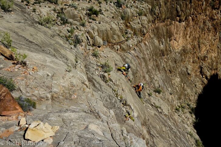
Low class 5 scrambles are standard when doing attempting this route. Photo by Rich Rudow.
Access to safe drinking water is limited
Flash floods are common
Route requires low class 5 scrambling
Route-finding is extremely challenging
Terrain is hostile as it chews through clothing, gear, and shoes
Weather is unpredictable
The temperature is hot but can quickly change
No towns or resupply for much of the 700 miles
Mostly off-trail
No guidebooks or beta
I did it—57 days and 20 pounds lighter. I thru hiked the Grandest cathedral on the planet. How? I wondered that myself. But, I’ve spent half my life preparing for this trip. – Rich Rudow
Climbing Vishnu Temple. Photo by Rich Rudow.
How did the trip go for the group?
After spending months crafting a day-by-day, detailed route, the crew started with six hikers at Lee’s Ferry. Only three were slated to finish the whole trip (Rudow, Atwood, and Dave Nally), but even some of those that were going part of the way found the heat too much to handle and left earlier than expected. Both Nally and Rudow suffered from Giardia during the trip, and Nally left on day 23 due to a respiratory illness.
Throughout the traverse friends brought them fresh food to lift their spirits, satellite notifications informed them of inclement weather, and eight caches filled with food, new approach shoes, trekking poles, maps, and sleeping bags propelled them forward.
In the end, Rudow and Atwood emerged victoriously, a lifelong obsession with this wild place momentary abated and a renewed sense of commitment to make sure this place lives on.
Rattlesnake Canyon in the early morning light. Photo by Rich Rudow.
Rich also wrote down his initial thoughts about the trip and posted some photos from the adventure on his Facebook page 9 days after he and Atwood completed the trip
Community review / giveaway results for the Enlightened Equipment Apex-insulation-filled booties.
An Introduction to Community Reviews (Beta)
This article is a Backpacking Light Community Review. A few notes about this article:
These are not official “editorial reviews,” in the same sense that we publish those under the categories of “Flash Reviews,” “SpotLite Reviews,” or “Performance Reviews.” These are short, informal reviews conducted by Backpacking Light Members who are not required to adhere to normal product review program standards.
The manufacturer/brand submitting products to the program sponsors the Community Review Program, and they pay a fee to participate in this program. We thus label this type of content as “Sponsored Content” to distinguish it from independent, objectively-developed, editorial content free of third-party influence or a need for us to otherwise meet obligations to another third party.
Our obligations to manufacturers/brands participating in this program are only to (a) promote the availability of a Giveaway/Community Review opportunity to our membership; (b) select the participants; (c) consolidate participant reviews; and (d) publish this content.
SPONSORED BY
Enlightened Equipment (EE) developed a prototype light-weight synthetic-filled bootie for this program. We issued a call for testers to receive the complimentary giveaways, and we selected them (primarily) on a first-come-first-served basis. Participants sent their contact information to the manufacturer, who shipped the product samples.
A condition of being a participant was that each participant would supply a short review (with a photo or two), by a deadline after a preliminary evaluation period.
What follows are the participants’ evaluations of the product.
EE Booties. Photo by Mike Gunderloy.
Barry Cuthbert
I was given a pair of 4 oz (113.4 g) Apex (15ºF – 30ºF) (-9.4ºC to -1.1ºC) booties in size small in black/black/sunrise, where the inner and outer material are black with sunrise trim. The booties appear very well-made. When my two kids (the actual testers) saw them there was an intense debate about who was going to wear them first.
In a New Zealand mountain hut. Photo by Barry Cuthbert.
The small size is equivalent to US men’s size 4 – 5.5 or US women’s size 5.5 – 7. The testers (my kids) have US size 6-7 feet; they said that the booties fit well even when they were wearing socks.
We tested the booties on an early spring weekend trip to a sub-alpine hut in the Tararua Ranges of New Zealand. My children tested the booties while moving around inside the hut and while sleeping. The testers considered “moving” to include running, jumping and climbing while playing various games on plywood flooring and wooden ladders. The booties held up well to the treatment by remaining in place without slipping and by incurring only very slight wear on the sole.
The inside air temperature of the hut fell to freezing (32ºF/ 0ºC) but the testers said they had very warm feet and they never complained of cold feet. This experience suggests that the upper limit of 30ºF (-1.1ºC) is reasonable for these “4 oz” (113.4g) booties. We weren’t able to confirm the lower limit of 15 F/ -9 C.
Wear on a sole after some abuse. Photo by Barry Cuthbert.
Each of my kids would definitely like to have their own pair of booties. I would like to see a slightly thicker fabric on the sole of the booties (at least for the kid’s sizes) so they are more robust for those times when a game of tag is impossible to resist.
Our thanks to Tim of Enlightened Equipment for providing the booties to review.
Greg Allen
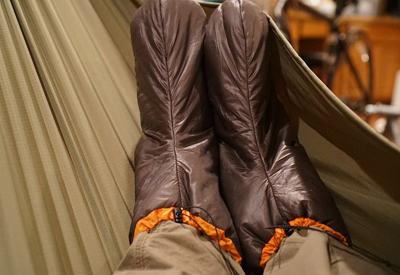
One month ago I received a pair of Enlightened Equipment Sleeping Booties, size L (mens 8-9/womens 9.5-10.5), 2.1 Apex fill (30 – 45ºF)(-1.1 – 7.2ºC). On first look I was quite impressed; I’ve never had real sleeping booties, just thicker wool sleeping socks. The finish and craftsmanship were excellent. All seams, inside and out, were flawless. Tiny shock cord and mini cordlocks functioned perfectly. These weighed in at 1.6 oz. (44 g) on my scales and packed in a stuff sack about the size of a baseball. In practice they are stored while hiking in a small gear bag at the head end of my gathered-end hammock. When crawling into the hammock, I open the gear bag and beautiful fluffy booties are ready to go on my feet. I can feel immediate warmth when slipping them on. When we pack up or exit the hammock, we neatly stow them back in the apex gear bag. They never leave the hammock while on the trail.
Relaxing in a hammock. Photo by Greg Allen.
Due to a relatively warm fall in town and to an inability to get to higher elevations because of work, I’ve only had the chance to test these down to 45ºF (7.2ºC). Further testing will come later this fall and winter. As previously stated, I experienced immediate warmth when slipping the booties on. My feet were then tucked into a Revelation Overquilt (also an EE product). I was able to fall asleep quickly and did not notice any cold spots. Waking at night I had warm feet, but my exposed arm was a bit chilly. I heeded the website warnings and exchanged the booties for cold trail runners on a 2 am plant watering trip. Booties immediately warmed my feet upon reentering the hammock, but as always, that is a long cold two-minute outing. I might try slipping my untied runners over the booties next time I am out.
Moisture is rarely an issue with my sleep system here in Colorado, but I do imagine these will perform better than down booties when there’s a little foot sweating. Drying them during the day is less of a concern. I continue to be impressed that these are so light and packable. The compression and weight penalty for something as small as booties is negligible, even for a gram counter like me. The trade-off for better performance when wet and faster drying is worth it. Durability will have to be assessed at the end of a season or two, but so far it is good. I have been very impressed with durability of other EE gear I own, even very lightweight fabrics.
The booties are of excellent construction and design. The performance was better than expected, but I have yet to have them down to the lower limits of the rating. The size and weight are better than expected. As for durability, I do not yet have enough data. I would purchase these over a pair of more expensive down booties after this testing.
Ken Guan
The socks appear to be very warm. They are of beige interior, and royal blue exterior. The material is silky. We have not tried them on yet in the field as it is still warm, and we are caught up with other things. From my previous experience, I used a pair of down socks for myself, and I get hot at some point during the night. But, I would still prefer to sleep with the socks on. My left foot turns cold during the night. Maybe it is because blood circulation.
Booties at home. Photo by Ken Guan.
I got this for my mother or my wife. I will send more pictures once they try them on. They are definitely of great quality, and will last. I think they can even walk in them at home.
9-year old daughter of Mike Gunderloy
Booties elegantly modeled. Photo by Mike Gunderloy.
I tested the 4 oz. (113.4 g) Apex 15 to 30º F (-9.4 to -1.1ºC), size small, color coyote/forest/navy bootie. These booties were super comfortable. I would wear them almost all day if I could. I didn’t take them into freezing temperatures, but the night-time low on my test campout was in the mid-40s ºF (4.4ºC). I was sleeping in a hammock (and using an Enlightened Equipment underquilt), so it would be colder than it would be in a tent. But that didn’t matter. My feet were still warm.
I had to go to the bathroom in the middle of the night, and my boots were wet (these booties are made for sleeping only, not for wearing around camp), so I had to put my boots back on. My toes got super cold and I wanted them to get warmer. It only took about 5 minutes for my toes to warm up again when I put on the booties again. And, in the morning, I had forgotten I was wearing them, because I couldn’t even feel the booties – that’s how light they are.
Booties with an attitude. Photo by Mike Gunderloy.
A pair in size small only weighs 1.9 oz. (55 g). The construction is simple: sole and wraparound upper with a drawstring top to snug them around your foot. The Apex insulation is even and doesn’t have any tendency to shift around or bunch up. And if I could choose for you, I would say to buy them.
Kelly Kading
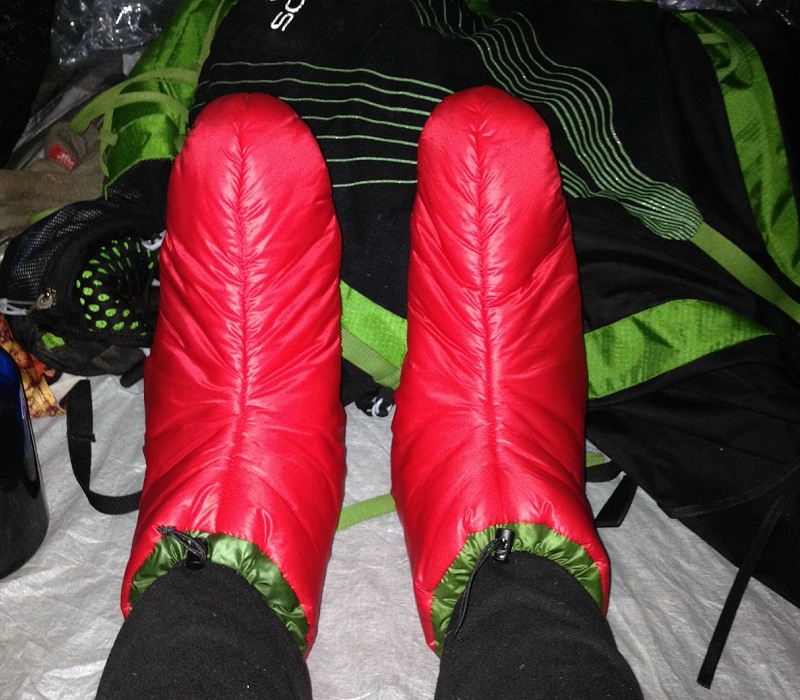
I tested the size XL; red and green; 3.2 oz (90.7 g); and 6 oz (170.1 g) Apex Booties. Enlightened Equipment created a hit with their Apex Booties. I was lucky enough to get a pair weighing 6 oz (170.1 g). I found the warmth to be slightly less warm than my down Western Mountaineering Flash Booties. I only experienced temperatures in the low 30s Fº(-1.1ºC) while testing (my feet were toasty), but I am confident they would be warm at least to the manufacturer’s specification of 15ºF (-9.4ºC).
Wet, cold feet during your break from snowshoeing? No problem for the EE Booties. Photo Kelly Kading.
Where the booties shine is their fabric. The fabric is wispy-thin while still retaining a good feel on the skin. My feet did get a little clammy while wearing the booties without socks, but it was hardly unbearable and well within the range of comfortable. This kind of experience is to be expected when wearing the booties at temperatures higher than the manufacturer specification. I was pleasantly surprised by their breathability and their water-resistance.
I was a little disappointed by the fit. I felt some slight constriction around my forefoot. I don’t necessarily have wide feet; I always find I have a “normal” width range when I measure them. But these booties do not fit me as well as some other brands.
Overall, I recommend these booties. When using booties in a humid environment, you can’t beat the mix of warmth, water-resistance, and light weight. The only area for possible improvement would be widening the forefoot area or making a wider bootie as a custom option.
Jennifer Mitol
Since it is still somewhat hot here in Central Texas, I haven’t been able to test the warmth of these synthetic booties as compared to my down pair from GooseFeet Gear. So without cold temps, I thought I would see how the synthetic booties dealt with moisture management compared to the down booties.
As a woman-of-a-certain-age, I frequently have a problem of, ahem, nighttime moisture management. I sweat a lot at night. I mean, a lot. So though I was unable to test the actual insulating properties of these guys, I was able to compare how wet feet worked in them.
Comparing down booties (left) with these EE Booties (right). Photo by Jennifer Mitol.
I have been using the Goosefeet Gear down booties for about 3 years now, and one of the big problems I have is getting into bed at night with kind of wet feet. Normally, I could put on some wool sleep socks and the moisture would go away. But with the down booties, I would just swim in sweaty feet for a while, or deal with cold toes while my feet dried enough before I put on the booties.
So to test, I came back from a run all nice and sweaty and put on the EE synthetic sock on one foot and the Goosefeet Gear down sock on the other. The down sock never felt comfortable, even in my air-conditioned apartment. The EE sock was a bit sticky for slightly less than 3 minutes (by my watch) before I noticed the moisture was no longer noticeable.
Warmth and comfort-wise, overall, I like the down socks slightly better, as they feel like puffy clouds on my feet and the EE synthetic socks feel like, well, socks. But if moisture is at all an issue, I would not hesitate to take the EE synthetic booties in their place. They would be far warmer than a pair of actual socks, and I was impressed at how fast the sweat from my feet ceased to be noticeable.
Pete Clarke
“Yeah! I’m excited! I get to check out some new booties!” When I told my girlfriend, she simply set down her book and glared at me. A long, evil glare.
For the record, these booties are the kind that go on your feet. The warm, snuggly kind. The kind that can replace “heavy” sleeping socks, and can squish down to the size of a baseball. I already own two Enlightened Equipment down quilts, and I think the balance between innovative design/brilliant technology/garage sale prices is exceptional. Now I own my first pair of synthetic insulated garments from them as well. How do they perform?
Comparing wool socks with EE Booties. Photo by Pete Clarke.
For starters, the APEX synthetic insulation rocks! Anybody out there who has second thoughts about this can rest assured – this stuff is impressive. The insulation is very warm, lightweight, and compressible. EE pairs it with an outer material which is smooth and silky, and a little bungee system to cinch the bootie tight around your ankle. Very simple. I used the 30ºF (-1.1ºC) version (the least insulation), which I find comparable to my heaviest wool socks. In fact, in order to figure out which is warmer, I spent several nights wearing an Enlightened Equipment bootie on one foot and a Wigwam woolly sock on the other. I found that they both performed the same! I also discovered that the wool socks weighed 3.5 oz (99.2 g) while the booties were only 2.1 oz (59.5 g). This is a little heavier than listed on Tim’s website [1.5 oz (42.5 g) in size L], but still quite a bit less than the sleeping socks I would normally carry. I will definitely bring the booties on my upcoming backpacking trips.
Are these 30 degree (-1.1ºC) booties worth the money? Now that I’ve had a chance to play with them, I would say no. If I was going to buy them, I would opt for the 15 ºF (-9.4ºC) or the 0ºF (-17.8ºC) versions. They are only a few dollars more, and quite a bit warmer. That would be the sweet spot for me!
Maxine Weyant
(Sent while on trail via mobile phone.)
I have used the booties every night for the last two weeks and am wearing them at this moment. In fact, they are bright red with a green lining. The color makes them easy to find in my pack.
Mine are I believe the warmest version, 0ºF (-17.8ºC). They didn’t arrive with any labelling on the packaging, but the weight corresponded to the weight on the website. Despite being the thickest version, they only manage to keep my feet warm when they are inside my down sleeping bag, and I still have to wear socks inside them. Just sitting around in my tent, my feet are quite cold and I can feel a cool breeze through them. So yes, they are quite literally, sleeping socks and that’s about it.
Booties in the tent. Photo by Maxine Weyant.
You can’t walk in them; the bottoms are too slick and the fabric too delicate to withstand abrasion. The manufacturer specified that they weren’t meant to be camp shoes, but I was hoping they’d keep my feet warm just sitting in my tent.
Granted, it’s been in the low to mid-30s (-1.1ºC). This particular bootie is made for even colder temps., however. I am a cold sleeper and usually wear a lot of clothes inside my 20ºF (-6.7ºC) bag, even if it’s 40ºF (4.4ºC) outside.
Roger Caffin
Sue and I have some BPL Cocoon synthetic jackets from when the BPL store existed. To be sure, they are not as warm as our full-on down jackets, but we have used them in the snow and have been “warm enough” inside our 2-layer winter tent. The great thing we have found about synthetic jackets is that they are extremely washable. Yes, we use Sports Wash of course, and they are no hassle at all for maintenance. Our idea for these EE synthetic booties was that they should be just as easily maintainable after trips.
In the past I have been using some fluffy white woollen socks I bought in Chamonix as bed socks; Sue has been wearing some other slightly heavier but similar socks. We don’t wear either of them in shoes, so they are still all soft and fluffy – and quite warm. But the socks weigh 3.2+ oz. (90.7 g) for the pair.
These 4 oz. (113.4 g) Apex Booties (the middle range) seemed to be a shade warmer than the socks for both of us, and they weigh only 2.0 oz. (58 g) for the pair. With my fluffy white socks I usually wore some very thin nylon liner socks inside as well, to keep them a bit clean. Those weighed at least .4 oz. (10 g) extra. Because these Booties are easily washable, I just dry my feet for a minute or two in the air, then I put them on. Usually, my feet don’t get too cold while they are drying off. I guess, with synthetic insulation, I could just put the booties on over my damp feet. So we are comparing 3.5 oz. (100 g) of socks with 2 oz. (58 g) of booties. Both Sue and I found that they were quite warm – in still air. We did not test them outside in the wind as we did not think they were meant for that: still air inside the tent on an air mat is where they belong.
Booties on the mat, bungee cord tightened. Photo by Roger Caffin.
I got the XLarge size, mens – 9.5/11.5, womens 11 – 13, as I take size 10 4E shoes. The booties seemed to fit about right over my feet. There is a loop of light bungee cord – hat elastic really, at the ankle with a tiny cord lock. We both found that was definitely a very good idea for keeping the booties on. Without the bungee cord the booties did tend to migrate off a bit when I was moving around. Also, having the bungee cord done up seemed to make them feel just a little bit warmer around the ankle region.
In short, both Sue and I loved them – but we only got one pair.
The Altra Lone Peak Neoshell: light, zero-drop, wide toebox, waterproof-breathable. An ultralight backpacker’s shoe for the fringe season?
Introduction
The Altra Lone Peak Neoshell (Gen 2.0) is a zero-drop, wide toe-box shoe designed to keep feet dry by preventing environmental moisture from permeating the shoe and by allowing breathability, thereby mitigating cold, wet feet. The obvious application in the context of our audience is for ultralight backpacking during the fringe seasons of fall and spring.
Consider the Altra Lone Peak Neoshell for ultralight backpacking in fringe seasons. Aggressive sole, zero-drop, wide toe-box, durable outer. Photo: Altra.
Features and Specifications
Weight: 11.9 oz (337 g)
Key Features:
Toebox: wide;
Cushioning: moderate;
Midsole: dual layer EVA;
Outsole: sticky rubber with aggressive tread lugs;
Insole: minimally supportive (no meaningful arch);
The author wearing Altra Lone Peak 2.0 NeoShell shoes with Northern Lites Snowshoes while hiking Mt. Ellis near Bozeman, MT. Photo: Stephanie Jordan
Performance Notes
My initial experience with the Altra Lone Peak 2.0 Neoshell shoes was taking a winter day hike in New World Gulch near Bozeman, MT, with the family and the dog. The daytime high was in the low twenties and snow flurries were persistent throughout the day. We strapped on our trail spikes and gaiters and proceeded about two miles to a viewpoint overlooking the south buttress of the Bridger Range. There were no stream crossings, and most of the hike was over a relatively good boot pack. The bootpack became lower in quality as we progressed to our turnaround point and temperatures cooled into the teens. Snowfall intensified on the return hike to the vehicles. My feet remained isolated from outside moisture, without sacrificing breathability. I had warm, dry feet. Granted, this isn’t a robust test of the shoe’s worthiness for extended backpacking, but in the context of this type of review (a SpotLite review, which provides a cursory overview of a product based on limited field use), it didn’t reveal any dramatic inconsistencies with manufacturer claims.
Update: Since I wrote the initial draft of this review, I’ve had the chance to hike several dozen miles in the Altra Lone Peak NeoShells, including several miles of overnight backpacking in winter (snowy) conditions, and my experience to date remains consistent with my initial performance notes.
Performance Highlights
The Altra Lone Peak 2.0 NeoShell shoes in combination with merino wool socks and gaiters have kept my feet warm and dry, even in subfreezing conditions while hiking over snow.
Because these are a low-top running shoe, optimum moisture sealing requires that these shoes be paired with a well-sealing gaiter (and a high gaiter at that, for snowy conditions) to prevent moisture from penetrating the shoe through its collar.
The shoes mate well with most snowshoe bindings that we’ve tried. Trail spikes (e.g., Kahtoola MicroSpikes) do not seat well on the front of the shoe due to the wide toebox. For most conditions, this isn’t a problem. For steep side-hilling, microspikes tend to slide off the toe of the shoe.
The author wearing his trail spikes while hiking in Altra Lone Peak 2.0 NeoShells on the Mt. Ellis Trail near Bozeman, MT. The shoes have deep, widely-spaced lugs for reasonable grip in soft snow and dirt. The lugs aren’t deep enough for reasonable traction in mud. Photo: Stephanie Jordan
Summary
Strengths:
The shoe fabric is waterproof and seems to breathe as well (or as bad?!) as any Gore-Tex fabric shoe.
The shoe sole provides good grip in loose snow, dense mud, and mixed conditions, extending its applicability to fringe seasons.
Heavily cushioned platform provides extra insulation during winter and allows for comfortable trekking while wearing a heavy pack.
Even when not using the Altra gaiters, one can use most gaiters with the product, as long as the gaiter seals well around the shoe’s relatively low ankle cut – test your gaiter fit.
The shoe is light – at less than 12 oz, it’s lighter than most waterproof-breathable trail shoes.
Limitations:
The laces that come with the shoe become loose in the cold and stretch significantly when wet. Replace them!
Without gaiters, waterproofing is less than adequate as a result of a poor seal between the tongue and the rest of the shoe. A gusseted tongue would be a valuable change.
Recommendations
I’ve been wearing Altra Lone Peak shoes for several years (since Gen 1) for all of my training, hiking and backpacking (including in the winter). So, I have to admit a little bias towards the NeoShell model, particularly as it gives me warmer, dryer feet during the eight months of the year I spend outside in Montana’s fringe and winter seasons!
If you spend lots of time outdoors snowshoeing or spiking in the winter, you will find that the Altra Lone Peak NeoShells, in combination with a pair of gaiters, keep feet warmer and dryer than non-waterproof models.
A low ankle collar and poor tongue seal render them prone to leakage at shallow stream crossings, or in deeper snow, especially without a very tight-sealing gaiter.
This Tarptent Stratospire 1 Review highlights one of the most livable and stormworthy lightweight solo tents available.
Editor’s Note 3/11/16: After publishing this review, we learned that the 5.1 oz vertical support poles we originally referenced are not recommended by TarpTent for strong winds or snow. Instead, they recommend vertical support poles that are 8.o oz and cost $32. These changes were made below.
The Tarptent Stratospire 1 is uniquely positioned as one of the most livable and stormworthy lightweight solo tents available.
Features & Specifications
Features
Dual entry, dual vestibules
Dual trekking pole support
Double wall design (inner tent & fly)
Silnylon fly + mesh or solid fabric inner tent
Design allows for dry interior when entering/exit during storms
Specifications
Sleeps: 1-2
Weight: 36oz / 1kg
Floor Width: 32 in
Floor Length: 86 in
Interior Height:48 in
Stakes Required: 6
Packed Size: 16 x 4 in
Cost: $309
My Take
I found the Tarptent Stratospire 1 to be a very comfortable solo shelter, with plenty of space inside and in both vestibules.
I liked being able to retract the fly doors entirely away from both vestibules for magnificent views of stars and alpenglow.
I’m not a trekking pole user – so the fact that it requires trekking poles makes its use a bit of a hassle for me, requiring the additional cost (minor, only $32) and weight (8.0 oz) of optional shock-corded aluminum poles.
I’m used to the simplicity of using single-pole pyramids for most of my backpacking, and while the Tarptent Stratospire 1 is not difficult to pitch with practice, there are still two poles, two strutted corners, and six stakeout points to adjust to get everything perfect.
The tent pitches extremely tight – owing to its use of structural elements and strong silnylon fabric: it should hold up well in storms.
Strengths
The Stratospire 1 is particularly unique for its livability and its stability.
Livability: dual side entry, dual vestibules, lots of usable interior space, plenty of headroom – sacrifices often made in other ultralight tents.
Stability: Carbon fiber struts, dual pole support, hexagonal design, strong silnylon fabric – all of these design features result in the ability to create a highly tensioned structure that distributes wind loading well.
Modular inner tent can be left at home to save weight, or swapped with a solid fabric inner tent for winter use.
Limitations
More complex (but not complicated…) to set up than simpler 1-pole structures (i.e., pyramids).
Silnylon fabric is less resistant to condensation than Cuben Fiber.
Complex design, inner tent, and structural elements contribute to a relatively heavy weight for a solo shelter.
The Tarptent Stratospire I has been nominated for a 2016 Backpacking Light Guide’s Gear Award, and is currently undergoing extensive field testing in extreme weather conditions in all four seasons. We are evaluating it for both its wind and snow loading, as well as use as a winter shelter with its solid fabric inner tent. A comprehensive review is planned for later this year.
Backpacking Light is currently sponsoring a research project with the Montana State University Department of Mechanical Engineering to evaluate the effect of shelter design on wind load distribution. The Stratospire 1 is one of the shelters being investigated in this study, and we are looking forward to seeing how it performs under high wind loads.
Acknowledgments
The author wishes to thank Ryan Jordan for putting together the preview video shown above, highlighting the TarpTent Stratospire 1 features.
The author presents manageable solutions to improve performance of the Nigor Didis 2 Tunnel Tent using an MYOG / DIY approach that can be applied to any tent.
The Universal TrailPix, two trekking poles, and one additional pole make a tripod capable of holding a compact or small DSLR camera. The TrailPix consists of a triangular and mostly flat piece of aluminum with three holes in it for trekking poles. Thumbscrews secure the poles in place.
Introduction
The Universal TrailPix, two trekking poles, and one additional pole make a tripod capable of holding a compact or small DSLR camera. The TrailPix consists of a triangular and mostly flat piece of aluminum with three holes in it for trekking poles. Thumbscrews secure the poles in place. A lighter weight model is available without the thumbscrews.
The Universal TrailPix is a simple tool used to make a tripod from trekking poles. The three thumbscrews in the device that secure the poles are easily fixed within the tool, preventing them from accidentally coming out. Another thumbscrew mounts a camera or a ballhead on the tripod. Photo by Jeff Burns.
Features
Universal TrailPix:
Connects to trekking poles and cameras with minimal hardware
Works with most trekking poles
Can be attached to small cameras directly
Is typically used with a ballhead
Specifications
Universal TrailPix:
Weight: 2.4 oz (68g)
Camera Mounting Screw: ¼”-20
MSRP: $40
Performance of the Universal TrailPix Tripod
Recently I completed an eleven day backpacking trip at the Philmont Scout Ranch in northern New Mexico. I enjoyed the once in a lifetime experience with my son and some scout friends. I wanted the image quality from a DSLR camera. Since all the members of the crew used trekking poles, I was able to create a tripod using the TrailPix.
Before the trip, I ordered the TrailPix and searched for a ball head. The manufacturer of the Universal TrailPix sells two different ball heads, but both appeared undersized for a DSLR camera. I found the Really Right Stuff BH-25 to be an excellent fit, but also expensive. I opted for the Joby Ballhead X typically sold with the Joby Gorillapod but also available separately for just $43. It is very serviceable but is slightly too large to mount directly to the TrailPix. A spacer made from a section of curtain rod readily solved this problem. The Joby Ballhead X and a quick release plate for the camera weigh 9.26 oz (262 g). Assembled, the Universal TrailPix, Joby Ballhead X, spacer, and lanyard weigh 11.6 oz (330 g).
The Joby ballhead is a bit too large for the TrailPix, but a spacer allows the poles to attach. I replaced the thumbscrew that came with the TrailPix with a ¼”-20 bolt long enough to pass all the way through the spacer. Photo by Jeff Burns.
The TrailPix makes it possible to get shots that are almost impossible without a tripod. Group pictures are an obvious use. The Universal TrailPix also works well for sunrise and sunset shots. I even used it for astrophotography.
Performance Summary
Setup and use are quicker than field improvised solutions.
Hanging a weight from the center of the tripod improves stability. I used an MSR dromedary bag.
Three poles are necessary. I made an accessory pole from an old tent pole, but the manufacturer sells a ready-made pole.
Summary
Strengths
Combined with an appropriate ballhead and trekking poles, the TrailPix makes a workable substitute for a traditional tripod.
The Universal TrailPix is lightweight. The user can select a ballhead and thus, effect the total weight of the device.
Limitations
A traditional tripod is potentially more stable and faster to set up.
There is limited ability to adjust the height of the tripod.
Trekking poles aren’t always available. They may be holding up the tent when you need the tripod.
The thumbscrews make small marks on the trekking poles.
Recommendations
I am very pleased with the Universal TrailPix, and will continue to use it for hiking when bringing a regular tripod is not possible. I would opt for the BH-25 ballhead from Really Right Stuff instead of the Joby Ballhead X if I had no budgetary constraints. The Joby ballhead works well but is not the lightest option available. For use with a compact camera, I would choose one of the very small ballheads available directly from TrailPix.
Taking a tripod into the backcountry expands photographic options. The Universal TrailPix keeps the weight and bulk of carrying a tripod at a manageable level.
Many options are available for attaching a small camera to your trekking pole. Most are only suitable for small compact cameras and are more of a monopod arrangement. The TrailPix is unique in its ability to provide three legs and enough support to hold small to mid-size DSLR cameras.
This feature requires an active Backpacking Light Membership.
Premium Articles
You're currently viewing a free preview of a member exclusive premium article. Our premium articles include in depth journalism and insights from the Backpacking Light editorial team.
Get full article access by subscribing to a Premium or Unlimited Backpacking Light membership!