


Introduction
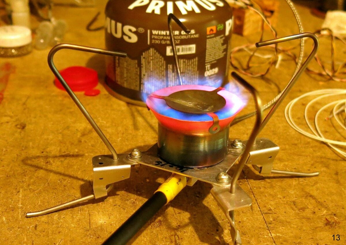
Herewith, my latest remote inverted canister winter stove.
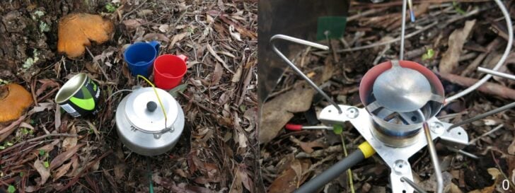
On the left, the V8 stove has disappeared into my Trangia kettle, while on the right, I have removed the kettle so you can see the stove. It weighs 75 g, including a long carbon fibre handle. There is a 76×400 mm titanium foil windscreen around the stove, weighing all of 12.5 g.
But before I tell you the tale of the stove, let me give some background to my stove-designing games.
Background
My stove adventures probably started when Brunton sent me their ‘Stove Stand’ for review. This cute device converted a high, wobbly upright canister stove into a more stable and lower one, with the canister off to one side, safely out of the way. Well, that was the idea, anyhow. It worked, and I reviewed it here many years ago.
It was a cute idea, but so limited: the canister still had to sit upright, or liquid fuel would appear on the jet, and you would get an exciting flare-up. I did wonder whether this could be fixed. Perhaps a strip of copper running down from the flames to the metal inlet fitting might carry enough heat for vaporisation? The Alpine Bomb (check the web) does this after all. So I experimented.
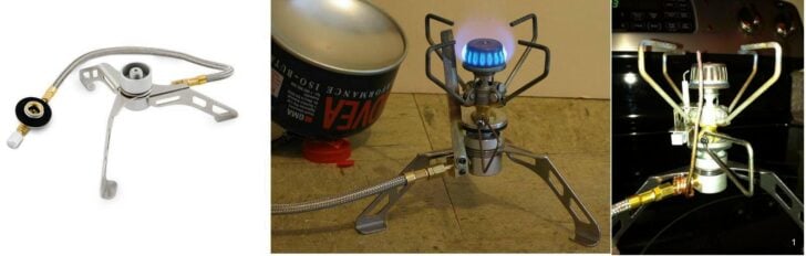
On the left, we have the basic Brunton Stove Stand. In the middle, I have put my GST-100 stove on the stove stand and added a copper strip from the flames to the input fitting, to vaporize the incoming liquid fuel. As you can see from the inverted canister behind it, this idea worked fine. I call this stove my V0. After I published this, Christopher Whitter had a go, using heavy copper wire (photo on right), and this too worked fine.
This got me thinking about remote inverted canister stoves for winter trips. To be sure, some commercial units existed at that time, but they were a bit heavy. Some of them were straight-out clumsy. Could I do any better? I would need a stove (or burner), a hose, and a canister connector (plus my wife really did not like the kerosene fumes from my Coleman Peak Apex II stove).
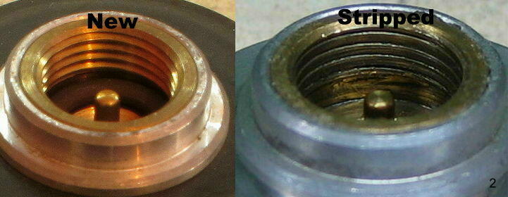
About the same time, my GST-100 stove failed partway through a 2-month-long trip in Europe’s Pyrenees, due to the rough threads on the gas canisters chewing away at the brass thread. This rather annoyed me at the time, and I did not want a repeat of the problem. My canister connector should not screw onto the canister like this.
Obviously, a better canister connector was needed. At the same time, I wanted a design with two valves: one good control valve somewhere near the burner and one fast-acting on/off valve right at the canister for safety. Fairly obviously, the control valve had to be on the gas flow rather than on the liquid flow if I wanted fine control of the flame.
The Original Stove (V1)
You can review my original design process of the stove, catalogued through five installments below:
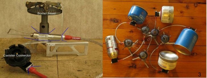
Leaping ahead a bit, I ended up with this (left photo). A stock burner top on a stove body of my own design, sitting on some support legs, a Heat Shunt (unlabeled) from the flames to the stove body, a light hose, and a versatile canister connector. A ‘light hose’ means that the hose should be flexible, unlike many commercial offerings. The connections at each end of the hose should be able to rotate, so the hose could sit flat despite any curls. The photo on the right shows the same connector attached to screw-thread canisters, CampinGaz canisters and the very light Coleman PowerMax canisters. And it does show the curls in the hoses.
The latter two canister designs have connectors which rely on lugs under the rim of the Lindal valve rather than a screw thread on the central spigot, and are in my opinion, far more reliable. Shades of Betamax. In the early days we could only get the CampinGaz canisters when wandering around in Europe, but that is (usually) no longer a problem. Never mind: I wanted the option. In the end I sold about 115 of these stoves around the world. They are V1.
I did not feel like machining 115 of these by hand, relying on every one to be identical. I may be good, but I’m not that good! And for reliability, I wanted all the parts to be interchangeable. So I bought a small CNC machine to do it for me. Programming a CNC is utterly different from writing a program for a conventional computer, so learning how to do that was great fun. Yes, you can get CAD/CAM software to write the programs for you, but at this level of complexity you would be looking at very big dollars – maybe tens of thousands. Not for me.
Vortex Burners: V2 and V3
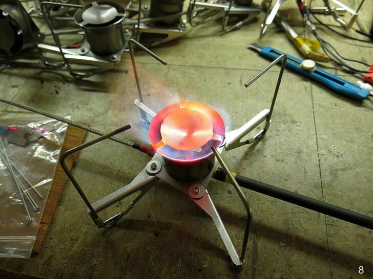
When designing the second and third versions of my stove, I was thinking about replacing the commercial burner top on the V1 when I got diverted into playing with Vortex Burners. This design is the same as the classic MSR XGK: a chamber with the flame inside and more flames coming out the top. It has no V1-style heat shunt per se; rather heat from the flames inside the burner chamber radiates down onto the base plate and the jet, heating the stove body underneath. (The MSR XGK has a ‘preheat’ fuel line over the top of the stove, in the flames.) A small point: Vortex Burners tend to roar a bit. My wife likes the noise: it means coffee or dinner is coming.
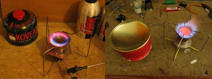
The version on the left was an early one, using titanium and stainless steel, to test the concept. It worked well, but it had two problems: it was heavy, as might be expected given the metals used, and the titanium wire pot supports were unreliable. They look nice, but they rely on ‘spot welding’ titanium wire, and that weld is not really a metal weld. It is just two wires mashed together under heat with the titanium oxide layer still between them. The joint will fail under load.
The version on the right has only the tips of the Ti wires in the flame, to get red hot. This is not only safer, it keeps the CO level right down. The glowing red disk in the middle is the splash plate, and it keeps the flames inside the chamber. Without it there, the fuel would shoot up in the air with dangerous consequences. It led to V2 and V3, which I sold.
V4: Upright Canister Stove
Tidying up everything after the V3, I found a box of incomplete upright burner head designs which I had been playing with but which I had abandoned for the Vortex design. I went back to experiments with an upright burner, and made the V4. It has internal baffles (inside the burner head) to mix and direct the gas. It used a Heat Shunt again. A motley collection is shown here in the left, with V1 stoves at the left and the venerable V0 (used across Switzerland) at the back. Some of the other designs in the photo – well, I was experimenting at the time.
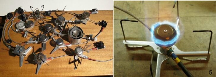
On the right we have the eventual V4 stove design. The design of the burner head worked nicely, but it was a bit complex to make. Several fiddly bits inside the head were needed to get the gas flowing in the right direction (upwards to the pot), while not adding too much weight.
Out of all this I identified a major problem: not in the stove itself, but how to support the stove and the pot. The thing is that one has to be able to pack the stove away into a small volume, and that means the legs have to be able to be folded up a bit. In the left photo some rather nice titanium zigzag legs may be seen (try bottom right). They were nice, but tricky to make and they required rather a lot of sheet Ti. On the other hand, the wire legs on the right proved to be quite strong enough, and much lighter.
Thermal Balance
As part of the V4 design, I had to work out what size heat shunt (taking heat from the flame to the stove body) should be used. Obviously the stove body has to get hot enough to (very) reliably vaporize the incoming liquid fuel so no liquid fuel comes out the jet. After all, you do not want any flaring inside a tent in a storm in the snow. At the same time the stove body must not get too hot or it will damage the Viton O-rings and the PFA tubing. Both of these have an upper temperature limit of about 250 C, or a bit lower (figures from different vendors vary a little bit). I strongly prefer that all temperatures stay below 200 C; I prefer about 120 C.
Basically what is needed is a balance. Heat coming down the Heat Shunt from the flames should match the heat required to vaporize the fuel as it enters the stove body. Now, to get this balance in the range from a very low flame to a very high flame is a bit tricky. By this stage I was doing a fair bit of temperature measurement using my marvelous LabJack data logger. The graph here shows what is going on and some of the problems (and the value of real measurements). It does not represent the final V4 stove design of course.
Now, what do the measurements look like?
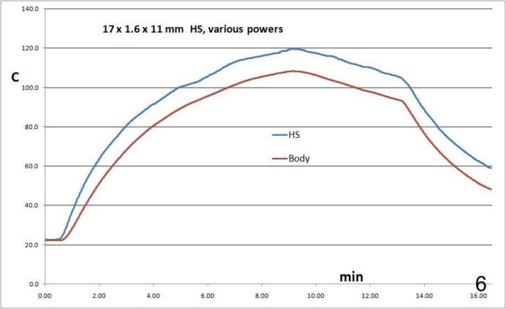
The blue line labeled ‘HS’ is the temperature near the top of the heat shunt (but not in the flame). The red line labeled ‘Body’ is for the stove body. At the start the fuel feed (at a low power) was gas, not liquid, the stove heated up, and the canister cooled a bit. Around 9 minutes (just an experiment) the canister was inverted and vaporizing the liquid fuel started to take energy from the stove body. The body started to cool down, dragging the splash plate down with it. Yes, they are coupled.
Around 13 minutes the power was turned up a fair bit, more liquid fuel came in, and more energy was sucked out of the stove body. Around 16 minutes the stove body had cooled to just over 40 C in my lab at about +20 C. In the snow the stove would be hovering on flaring. Now I know what is going on, and how to measure it.
Since most of this work is done in my lab at +20 C rather than in the snow at -20C, I needed some way of converting the results from ‘lab’ to ‘snow’. It seemed reasonable to just subtract 40 C from the measurements. This is not perfect of course, but close enough. And remember: the ‘boiling point’ of a 70/30 mix of n-butane and propane is around -24 C. Below that everything gets a bit more tricky, and I go home anyhow.
V5 Design
This was meant to be a simpler burner head to replace the commercial ones in the V4, and to be simpler4, but in the end nothing gelled well enough. Part of the problem was that I lacked the facility for hot forging of sheet titanium (while Asian factories have that). I can form sheet aluminium, but it melts too easily. Pass on.
V6: another Vortex burner
And so I returned to the Vortex Burner concept. It would seem simple since it does not need a Heat Shunt. However, there were some complications I wanted to examine. Obviously the stove body has to get hot enough to (very) reliably vaporize the liquid fuel. You do not want any flaring inside a tent in a snow-storm. So – measurements.
In particular, I was monitoring the temperature of the stove body, where the fuel comes in, and the flat (base) plate between the stove body and the titanium burner chamber. My theory at the time was that the flames heated the base plate, and that the base plate heated the stove body bolted to it. It turned out that there is a bit more to it than this. Anyhow, this graph shows the stove heating a litre of water in my Trangia kettle, but with a twist.
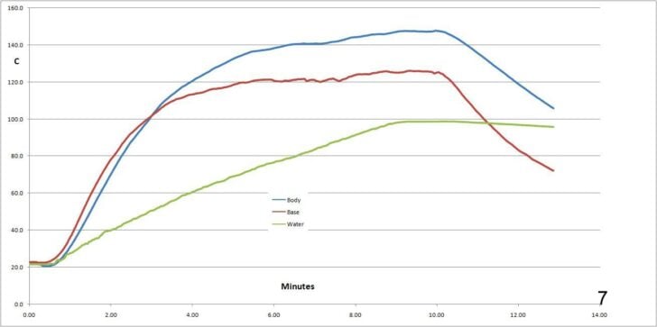
What might appear strange in this graph is that the stove body (blue) seems to have got hotter than the base plate (red). Normally the plate should be 20 – 40 degrees hotter than the stove body. The explanation is simple: the temperature probe for the base plate is a fair distance from the stove body, right out at the edge of a largish base plate, and was subject to air cooling. You do get such cooling when everything is above 100 C! As this shows, understanding what is going on and exactly what is being measured is essential.
The important bit from this graph is that the stove body got just a bit above 120 C and no further. Given that this was measured in my lab, at an ambient of +20 C, it would be reasonable to say that the stove body would still be at +80 C or more when in the snow with an ambient at -20 C. That is, subtract 40 C from everything. Nonetheless, the stove body is far above the boiling point of liquid butane, which is around 0 C. This is ‘satisfactory’.
An important detail which is not apparent from any of this concerns the air flow into the chamber. A small excess amount of air mixing with the fuel is fine: it ensures complete combustion and avoids the release of the deadly carbon monoxide CO. On the other hand a larger excess of incoming air just has to be heated up without contributing anything to the flames. An excess is simply a drag on the flame temperature, reducing the efficiency. Also, the excess air made lighting the stove difficult (explanation later). A balanced amount of air is needed.
The final design of the V6 is shown here. I sold some of them.
V7: SUL
By this stage I thought I had finished designing stoves, but a little demon crept in and got me wondering about SUL. To be sure, commercial remote inverted canister stoves are all heavier, while mine are generally about 90 g. But I wondered: how low could I go? I started to fiddle.
First up, it seemed that a Vortex Stove would not be a candidate for SUL, so I focused on the V1 design: a base with an upright burner. I could see several areas where an upgrade would be possible. A lighter canister connector, a lighter hose, a lighter stove body, and a lighter burner head.
I will briefly mention the hose. Commercial manufacturers don’t want to mess around: they buy high temperature reinforced fuel hose by the reel. This stuff was made for the race car people: it is very ‘robust’ and stiff and abrasion-resistant. Well, fine for race cars, but what has that to do with my little stoves? A bonus maybe is that it is mostly proof against novice users as well. I wanted better. Some PFA tubing with 2.0 mm outside diameter with some custom stainless steel braid was chosen: a bit thinner than the 3.2 mm PFA hose I had used on previous models.
This project ended up as V7, weighing only 45 g complete. It uses a BRS-3000T burner as the lightest available, plus the BRS-3000T has its own pot supports. The design needed a stove support of course, and this needed to be detachable for packing.
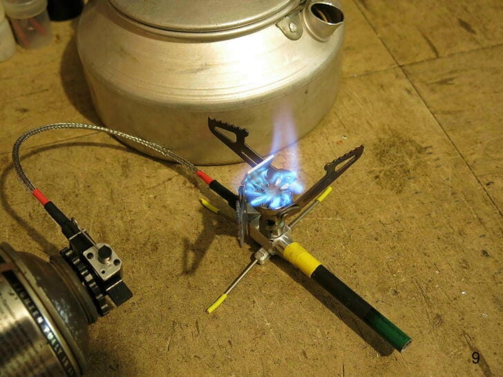
I had to use a lot of data logging in designing the Heat Shunt, to get balanced heat flow at OK temps. First of all, in my excessive enthusiasm for weight reduction, I had dispensed with the Heat Exchanger part of the stove body see previous stove articles). That did not work! Then I had to pick the right Al alloy for high thermal conductivity. The common 5005 alloy proved significantly better for this than the 5082 alloy I had been using. Then I had to design the top bit where the flames hit, to get heat into the shunt. What was interesting here was that at low power the flames hit the heat shunt nicely, but at high power the flames could go past the heat shunt – just when more energy was needed to vaporize the increased flow of fuel. This was soon solved: I bent the tip of the heat shunt slightly into the flames. You can see this in the photo.
My NEW V8 Vortex stove
I had a number of queries here: could one even make an SUL vortex burner for a start. That concerns the size of the burner chamber: would a mini-burner-chamber work? A second query was whether I could make the legs or pot supports more elegant (or more sexy if you wish).
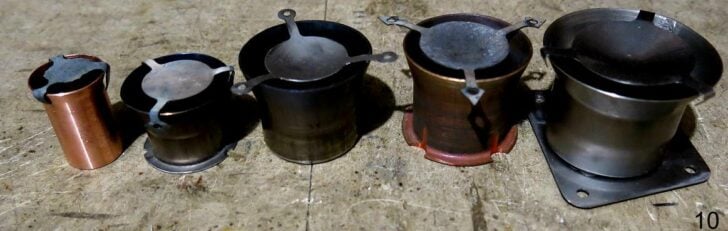
This photo shows some (not all) of the burner chambers I tested. But first let me deal with the other bits of the stove. I won’t cover the ‘new’ canister connector as that has been well covered in the V7 article. That leaves the hose and the legs.
Member Exclusive
A Premium or Unlimited Membership* is required to view the rest of this article.
* A Basic Membership is required to view Member Q&A events


Discussion
Become a member to post in the forums.
Companion forum thread to: MYOG: SUL Remote Inverted Canister Winter Stove V8
An ultralight winter stove is simple in concept—but devilishly complex in execution. This deep dive traces the evolution of a remote inverted-canister stove through eight generations of design, testing, and refinement. The result is a 75-gram V8 vortex stove shaped by careful experimentation with airflow, thermal balance, burner geometry, fuel vaporization, and field-worthy component design.
First of all, another excellent article about the design and thought process going into developing a stove. Congrats. I was impressed with the V7 design and your ability to get the weight down to 45 g (not including legs). So, the V8 is about 15 g lighter than your previous versions? How does the fuel efficiency compare (V6, V7 & V8)?
I may have missed it, but what is the advantage of the shut over a pre-heat tube? I tend to like the pre-heat tube as in fair weather, you can use it in the upright position.
Finally, what are your thoughts on the Fire Maple Petrel Summit? It looks like a solid replacement for the Kovea Spider. I just bought the Petrel Summit but have yet to have time to test it out.
Hi Jon
I was impressed with the V7 design and your ability to get the weight down to 45 g (not including legs).
Correction: that 45 g is with a short CF handle and does include the legs. 45 g complete.
Fuel efficiency in still air is about the same for most small stoves. Ignore all marketing claims. Pot size is usually more important. But of course if you run a small stove in the wind, it will cost you. I do not understand why anyone would not use a windshield. My Ti foil one for the V7 weighs 7 g.
Yes, there are bound to be some exceptions with worse efficiency.
Why a heat shunt instead of a heat exchanger tube over the top? Two main reasons.
The first is the weight saving: a small strip of aluminium heat shunt vs a long length of heat-resistant alloy metal.
The second, and far more important one, is manufacturing difficulty. That heat exchanger tube MUST be hermetically joined to the stove body, and that usually requires some sort of welding. Welding an alloy tube to an aluminium body is not easy. Yes, you could alternately use some sort of metal coupling, but that adds more weight and may not be all that reliable in the long term, given the differences in thermal expansion. So most companies use brass, which is much heavier.
I should add that you can always use one of my remote inverted canister stoves with the canister upright. But in cold weather you can run out of propane that way.
The FM Petrel Summit should be a reliable stove (imho), but for me it has two drawbacks.
The first is the weight: 111 g vs 45 g. OK, compared to the weight of a pack, the difference is not great.
The second drawback is the valving. The PS has only one valve, at the canister, controlling liquid flow. Controlling liquid flow to your required setting is far more difficult at the best of times, and always has a long time delay before any change happens. So for me, the fact that there is only one valve and no fast emergency shut-off, is a real deficiency.
Eh, well, I am of course biased!
Cheers
45 g for a stove is amazing. Although, like you said, the weight savings isn’t noticeable but combined with other weight savings it is.
why would you run out of butane in cold weather if you ran it upright?
OK, I am confused now. I thought that the latent heat of vaporization was needed to manage the temperature of the stove body.
Starting to see more and more off-brand stoves use heat shunts instead of tubes. I think it’s a really smart decision. If you think about it, it’s really just a clever rethinking of a well and long established principle in stoves. The burner bell on classic stove designs, the heat accumulator “star” in the base of newer designs from Primus and Optimus (Optifuel, Omnilite), they all do one thing: transit heat into the evap zone.
I think it’s superior in many ways. As Roger points out, I don’t think there’s an example of a preheater tube stove with a regulator at the stove. So fine adjustments are possible and it elimates the issue of tube fowling and is easier to manufacture. I think shunts/accumulators are both the future and the past of stove designs.
Roger, yet another banger of a post, one of my favorite series on this site! I just wish somebody would really rethink these ideas with liquid fuel stoves. Aside from the Soto Muka and Stormbreaker (wonderful stoves that are wonderfully complicated and intricate), LF stoves have not been advancing in years. Somebody should. It may be me some day. I have a few ideas.
The waste and weight of cannisters really bothers me.
Hi Jerry
why would you run out of butane in cold weather if you ran it upright?
It’s propane that runs out when the canister is upright, not butane.
Butane boils at ~0 C, but propane boils at ~-42C: physics.
So at -10 C, the propane is boiling off well, but the butane is sitting there doing almost nothing. You end up with a canister 2/3 full of liquid butane but nothing coming out. Well-known problem, and the whole rational for a remote inverted canister stove.
Cheers
Watching the evolution over the years has been inspiring. Keep up the amazing work.
Thank you.
Cheers
My V4 is still working perfectly…I’m really glad to see you continuing to innovate! Thanks for yet another great read. Looking forward to V9 and the blog that comes with it.
V9 ?@?@?#!#!%!%? ??
I may be running out of ideas!
But thanks for the info re V4.
Cheers
Become a member to post in the forums.