On all my inverted canister winter stoves I have managed to avoid running a vaporizing tube over the flame. While such a thing is necessary for white gas stoves and essential for kerosene stoves, my theory was that there was enough heat around that the liquid propane/butane mix coming from a canister could look after itself with just a little feedback from the flames.
Mind you, in the cases of V1 and V2 temperatures of the heat shunt (HS), stove body (body), and water for low/medium power they were vortex burners and my main job was to prevent the stove body from getting far too hot. The feedback from the flame vortex inside the burner was intense. In the cases of V1 and V4, I ran a heat shunt, a strip of aluminum, from the flames back to the fuel inlet.

The idea is that the flame would heat the end of the heat shunt, heat (or energy) would flow down the strip of metal to where it joined the stove body near the fuel inlet. There the energy would be absorbed by the incoming liquid fuel which would vaporize, go up and out the burner head, to make the flame.
By and large, this idea works fine. However, a recent customer for the V4 (Ian) reported some problems. He would prime his stove so everything was hot, then invert the canister for a liquid feed, and run it for a while. Then sometimes, after a while, the stove would start to hiccup and flare, and the stove body was found to be cold. What was going wrong?
I suggested various things by email, but none of them worked well enough. This was not good. A more detailed investigation was required. Fortunately, Ian was technically minded and was able to play with his stove a bit. Between us, we worked out what was going wrong and how to fix it. This is the story.
Details of the Problem
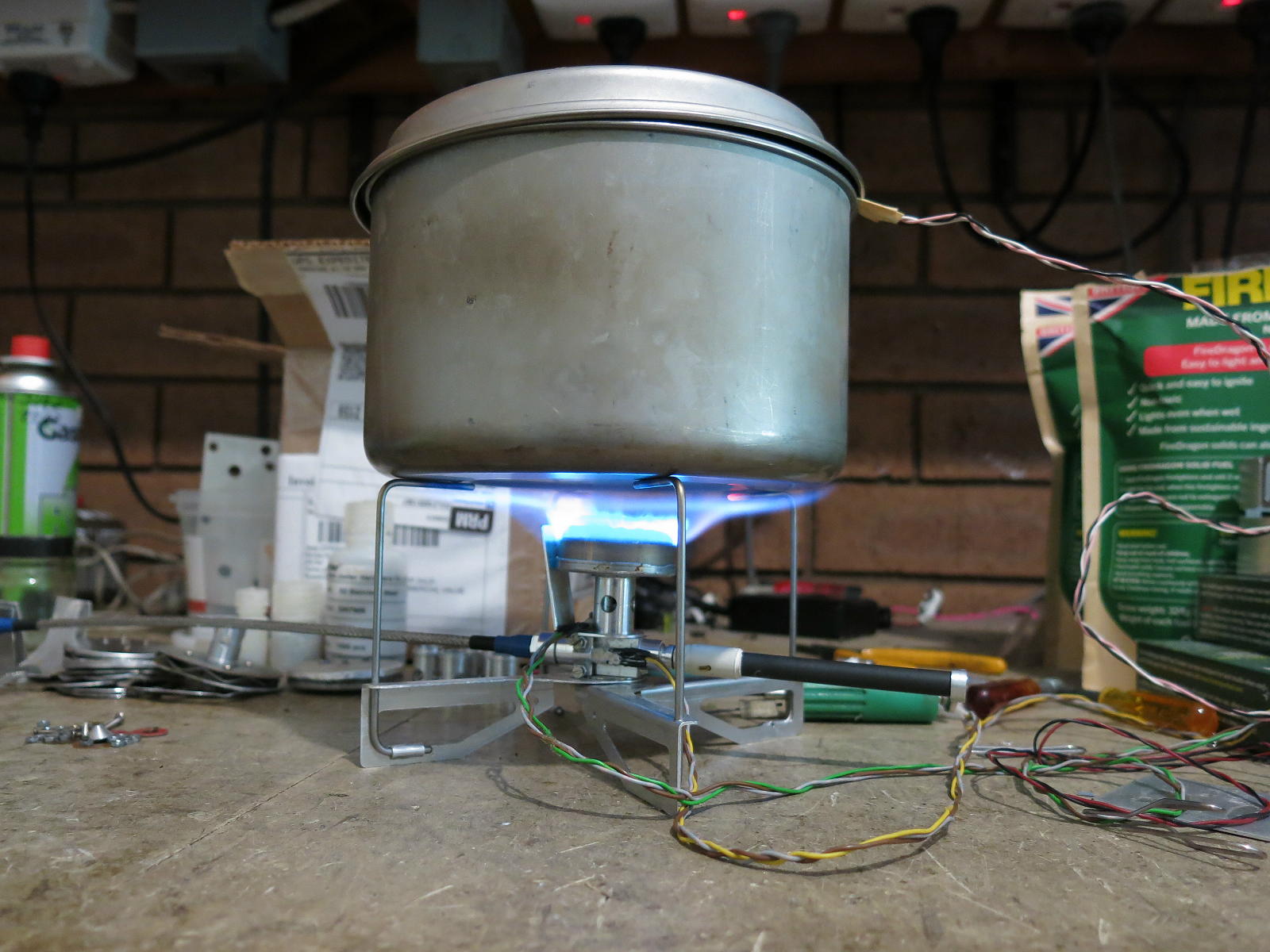
The problem did not happen under what I would call normal use. The stove had to be turned up to full power before the problem started. I do not run any stove that hard, and I recommend you don’t either, as it is rather inefficient in fuel usage. Full power normally means the flames are visible beyond the edge of the pot and a lot of heat is lost/wasted up the side of the pot. You can see this below and that was not really full power.
Now when the incoming fuel vaporizes, it uses up a fair bit of energy to go from liquid to vapor. Very often this energy comes from the canister or the fuel in the canister. This is why you may find that a canister will develop frost on the surface and stop giving off gas: it has lost so much energy that it has ceased boiling off vapor. (The use of the word boiling here is deliberate and correct.) In fact, this is why we use an inverted canister stove in winter, to prevent the canister from freezing up. Instead, the energy for boiling is meant to come from the stove and the flames.
So what this means is that the vaporizing fuel is sucking so much energy out of the stove body that the stove body is chilling to below the boiling point of the fuel. But surely the heat shunt is meant to be keeping the stove body and the fuel inlet warm, if not hot? Obviously not in this case.
You might wonder whether sticking more of the heat shunt into the flame might work. It might—until the aluminum melted. I do have one heat shunt with a slightly cooked end. This is not a good solution.
Analysis I
The first thing to do for me was to reproduce the problem. After that, I had to figure out why it was happening—in detail, so I could fix it.
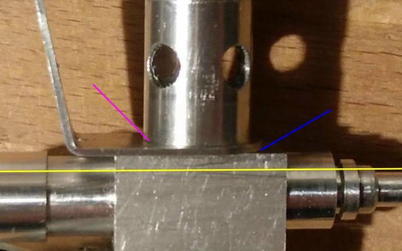
I had Ian try a few things first. Was the burner screwed down firmly so there was good pressure on the heat shunt (pink arrow)? Yes. Was there a gap between the heat shunt and the body (blue arrow)—a gap that would obviously be a poor conductor? No. Was the tip of the heat shunt in the flame? Yes.
Conclusion so far? There is not enough heat flowing down the heat shunt. Obvious in hindsight, I know. The next question is why not? Well, first I had to set up a test rig and measure things. I am a firm believer in having real measurements, not vague guesses.
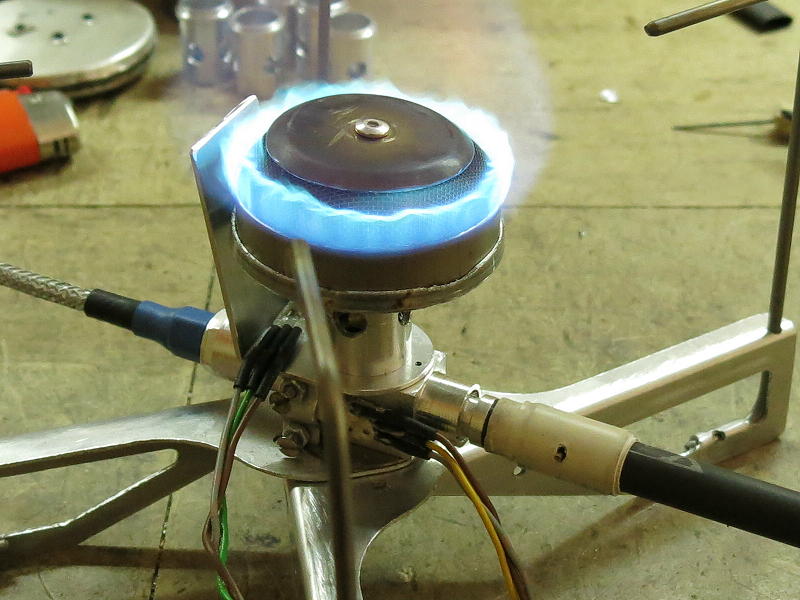
I attached two TI LM35 sensors (the little things on the ends of the wires in the above photo) to the stove. One is on the heat shunt itself (grey/green/brown wires) and one is bolted to the stove body (grey/yellow/brown wires). I had to modify my stove to clamp the latter sensor in place—two tiny stainless steel screws (M2 size) and an aluminum bracket (all visible in the photo). My expectation was that the heat shunt would be a bit hotter than the stove body, and it was. Then I hooked these up to my LabJack T7-Pro data logger and ran some burns. I used my titanium pot (~ 6 in / 160 mm in diameter) and 1 L of water as a load. Readings were taken at one-second intervals.
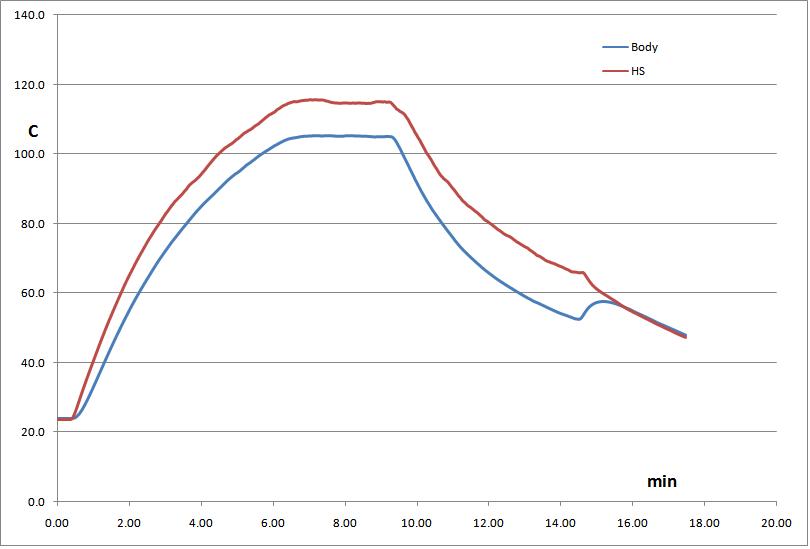
This shows a typical run at medium power. The stove is initially lit with a gas feed (not a liquid feed) and the temperatures soar. In this case, the red line is for the heat shunt and the blue line is the stove body. The temperatures (deg C) rise nicely so energy is obviously pouring into the stove body. As expected, the heat shunt is a bit hotter than the stove body. Time on the bottom axis is minutes—a lot longer than it takes to boil water under normal use.
I let the stove body get a bit over 100 C / 212 F for a bit of time (7 min) before flipping the canister over for a liquid feed. As you can see, when I did this the energy demand from the vaporizing fuel roughly matched the energy coming down the heat shunt, so the temperatures leveled off. Just after nine minutes, I turned the stove up to a bit of a roar, and the energy demand for vaporizing exceeded the available inflow—and so the temperatures dropped.
As the gap in temperature between the tip of the heat shunt (in the flame) and the stove body grew, so there was greater pressure for heat to flow down the heat shunt. The whole lot might have equilibrated in time with the stove body around 20 C (68 F).
Around 14 minutes, which is much longer than I normally run my stove for any cooking, I turned the gas off. The energy demand from the fuel stopped, but the heat shunt was still hotter than the body, so the temperature of the stove body rose to match the heat shunt. Then both decayed.
But this was at medium power. What would happen at high power—well beyond what I would normally use? Fairly obviously there would be a greater energy demand and the temperature of the stove body would fall faster/further—to the point where not all the fuel would vaporize and there could be some sputtering and flaring. And this is what Ian had reported.
Analysis II
Ian decided to copy the heat shunt with some thicker aluminum, to see if the greater thermal conductivity would solve the problem. I copied his idea with some 1.6 mm thick stock.
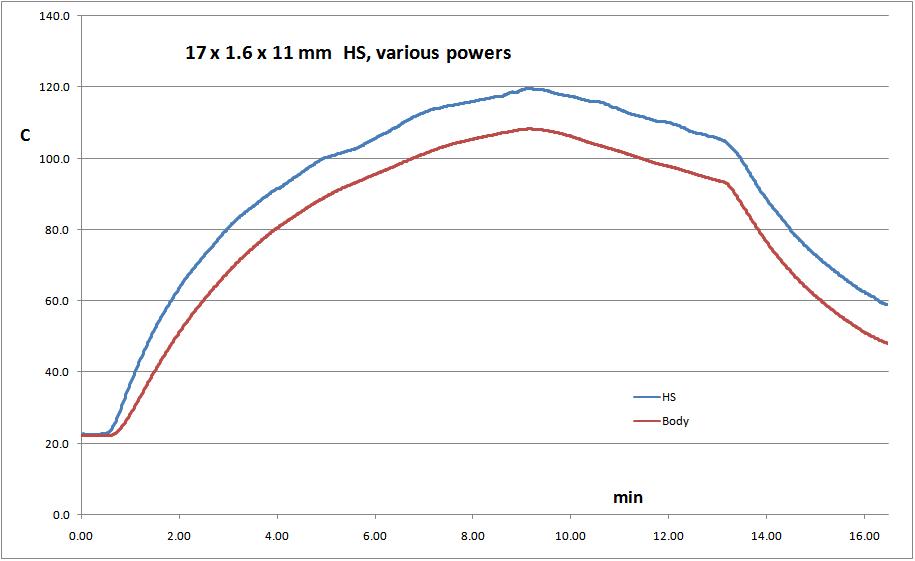
I started off at medium power and a gas feed for the first few minutes. Around three minutes I raised the power to high, although it is hard to see that. So far, so normal. Around nine minutes I flipped the canister to a liquid feed, and the temperatures started to fall, as before. Around 13 minutes I changed to high power, and the temperatures fell faster—again as before. That is, with greater fuel flow, more energy was sucked out of the stove body. This was for a heat shunt with a 60% greater thickness.
What is clear is that switching to high power is still demanding more heat energy from the stove body than is available. My interpretation of this was that the problem was not a lack of thermal conductivity down the heat shunt, but rather that there was just not enough heat energy coming into the heat shunt. That is, the heat shunt was starved of energy.
So I went a bit overboard to test this idea.

The original Heat Shunt has a tip that is ~10 mm wide sticking just into the flame – a millimeter or two. I made a double heat shunt: two arms, and I made the tips 20 mm wide. I stuck the tips 2 mm further into the flame as well. Overboard, right?
Member Exclusive
A Premium or Unlimited Membership* is required to view the rest of this article.
* A Basic Membership is required to view Member Q&A events

Discussion
Become a member to post in the forums.
Companion forum thread to: On Heatsinks and Thermal Balance
Roger Caffin troubleshoots the heat shunt on V4 of his inverted canister stove design.
interesting problem, analysis, solution
Verification – is meeting the design specifications
Validation – is meeting the customer’s expectations
High fuel flowrates at very cold temperatures is probably what is known as a corner / corner conditions. These cases can often be overlooked as they don’t happen often. Great job de-bugging and resolving the issue. The more you burn, the more you learn.
Fascinating test and analysis; I love me some graphs!
Thanks, Roger. I suspected something like that when the V1 did similar, ie flaring and running and flaring repeatedly. I simply bent the shunt a bit closer and ran it a bit harder. I am rarely out at those temps.
Hi James
Yes, that would work. The problem with the V1 was that I had to leave room for the folding legs, AND for rotating the burner head to remove it to clean the jet.
Cheers
Roger, My Whisperlite International has a vaporizing loop beside the burner. Same with a Fire Maple Blade 2 I got for my grandsons.
I do not see the advantage of adding a heat sink to inverted canister stoves with a vaporizing loop. Wrong?
The vapourising loop is the equivalent of my ‘heat shunt’.
The whole point of either one is to get energy into the liquid fuel so it turns fuel into vapour so it can burn properly.
Let us delve below the surface. The vapourising loop has to be welded or silver-soldered to the rest of the stove body to avoid having any gas leaks – which leaks would be extremely dangerous. But trying to make such joints in aluminium is difficult, so ‘they’ use brass, and a fair bit of it. Brass is heavy.
So instead of running the liquid fuel through a brass vapourising loop to get the heat into it, I have a separate Heat Shunt bringing the heat from the flame down to the liquid fuel as it comes into the much lighter and smaller aluminium stove body.
A secondary advantage is that I am valving gas at the jet (after the boiling region) rather than liquid fuel back at the canister, which gives me faster, finer and more reliable control of the flame.
Cheers
It has been very interesting to watch the evolution of your stoves over the years, thank you for taking the time to document the process in such detail.
I suspect there are two other factors involved, stoichiometric peak location, and gas velocity (dwell time). So you know from a candle that the hottest part is not near the wick but at the top, and that visibility is not a good measure of where the oxygen/fuel mix is perfect and therefore the most energy given off. So as you turn up the gas speed / volume, you will move that ideal ‘hot-spot’ further away from the burner.
The second issue is gas velocity. You’ll find that as the speed of the gas increases, the time that the hot gas spends in contact with the heatsink significantly decreases. To your eye the ‘glowing spot’ looks unmoving, so it makes unintuitive that each molecule of gas has less time to vibrate against the metal. If you threw some small light particles into the flame, you’ll see what I’m talking about. In addition, there can be vortices and disturbances in the flow that create ‘insulation’ between the flame and the shunt that increase a lot as gas speed goes up.
I would estimate that the increased heat of the flame should more than compensate for the decreased vapour pressure (to a point) of the canister, and in any case if that was the limiting factor, no amount of heat at the burner/shunt could increase the grams of fuel per second ‘boiled off’. The lowered temperature of the fuel is a factor, but I’d argue, secondary.
In order to assess and address the issues, to linearise the heat transfer so ‘small fuel, small heat, large amount of fuel, large heat transfer’ and have ‘one shunt that works for all fuel rates and temperatures’, I would look into the following:
– Small particles (ultrafine iron filings or soot / carbon would be my pick) sprinkled on the burner while using your phone in slow-mo record mode to work out the dwell time, vortices and actual gas velocity. You can ‘time lapse’ the shots (blur them all together) so that you can visually see the trace out of paths and compare different videos to each other as ‘one photo each’.
– A thermal camera is an easier way to get accurate temperature readings, you can get $200 IR cameras that plug into your phone.
– An advanced technique, that is actually surprisingly easy to use with little upfront cost is schlieren imaging, google that term and veritasium to see how to implement it for your set up.
– Convolutions to your shunt, bends that cause the gas to have to change direction or ‘get caught’ might help linearise the amount of heat delivered to preheat vs fuel delivery rate. A ‘spoon shape’ with some small corrugations (2-3mm bends at 90 degrees) would be my starting point.
Anyway, very interesting project, I wish you had a website where I could see the current model and all the stats and pricing, maybe one day!
Hi James
Much interesting speculation, thank you.
Yes, gas velocity will affect the heat transfer. I don’t want the velocity too high or there is danger of flame-liftoff. A lower gas velocity allows a longer contact time.
Thermal imaging – not with a phone as I don’t have one. :) Do I want to buy a full IR camera? Not yet.
Tracer particles in the gas flow – possible but what am I looking for here? The actual gas flow is quite visible from the flames and the emitting atoms. Can I get more info from this? I don’t know.
‘Schlieren imaging’ – yes, I know the technique and I have used it casually once or twice. Tricky in the limited space between the bright flame and the pot. I have looked at the results, but the 3D nature of the flames up close obscures the schlieren images.
Convolutions to the shunt – not found necessary so far. A 20 mm width seems adequate. Just tweaking the width and distance into the flame seems to have been adequate so far.
Pricing etc: email me direct via roger@backpackinglight.com for details.
Cheers
Thanks for responding.
Clearly you’re very across the design and what’s involved after having worked on it for many years, and perhaps there’s nothing I can add to your project, to clarify though:
– Schlieren imaging, even if completely obscured at the burner, can still reveal patterns of turbulence. In combination with the particle tracing, it can help you understand if there’s a buffer between the shunt and the flame, and if you’ve been successful in redirecting the flow for more engagement.
– So the advantage of tracer particles are that you can in a sense simply count the milliseconds that a particle is running past the shunt, how close it is to the shunt, and how brightly it is glowing, and that will help you create a shunt that engages more (catches more particles, ‘holds them’ for longer, catches more of the bright ones) as you turn the gas flow up. You could for instance create a shunt that redirected more of the gas flow down as the gas velocity went up (create a knife’s edge that at low velocity, the natural rising of the gas is entirely above the edge, but as the velocity goes up, the gas flow goes straight across and so gets partially directed down). This would have the effect of greatly increasing the amount of heat that gets sent down the shunt, and its width in that area would control how proportional it was to gas flow. It’s a lot of iteration to do this with guesswork and temperature probes, but much easier with glowing particles and/or IR cameras etc.
If you’d like any assistance, feel free to email, otherwise, love your work and I’ll likely be in touch when I start ultralighting again for a new stove!
Hi James
Thanks for the offer. Right now I am fully committed on a different project.
I suspect that changing the width will be sufficient for me. Some field testing will be needed in the snow.
Cheers
Become a member to post in the forums.