Companion forum thread to: On Heatsinks and Thermal Balance
Roger Caffin troubleshoots the heat shunt on V4 of his inverted canister stove design.
Topic
Become a member to post in the forums.
Companion forum thread to: On Heatsinks and Thermal Balance
Roger Caffin troubleshoots the heat shunt on V4 of his inverted canister stove design.
interesting problem, analysis, solution
Verification – is meeting the design specifications
Validation – is meeting the customer’s expectations
High fuel flowrates at very cold temperatures is probably what is known as a corner / corner conditions. These cases can often be overlooked as they don’t happen often. Great job de-bugging and resolving the issue. The more you burn, the more you learn.
Fascinating test and analysis; I love me some graphs!
Thanks, Roger. I suspected something like that when the V1 did similar, ie flaring and running and flaring repeatedly. I simply bent the shunt a bit closer and ran it a bit harder. I am rarely out at those temps.
Hi James
Yes, that would work. The problem with the V1 was that I had to leave room for the folding legs, AND for rotating the burner head to remove it to clean the jet.
Cheers
Roger, My Whisperlite International has a vaporizing loop beside the burner. Same with a Fire Maple Blade 2 I got for my grandsons.
I do not see the advantage of adding a heat sink to inverted canister stoves with a vaporizing loop. Wrong?
The vapourising loop is the equivalent of my ‘heat shunt’.
The whole point of either one is to get energy into the liquid fuel so it turns fuel into vapour so it can burn properly.
Let us delve below the surface. The vapourising loop has to be welded or silver-soldered to the rest of the stove body to avoid having any gas leaks – which leaks would be extremely dangerous. But trying to make such joints in aluminium is difficult, so ‘they’ use brass, and a fair bit of it. Brass is heavy.
So instead of running the liquid fuel through a brass vapourising loop to get the heat into it, I have a separate Heat Shunt bringing the heat from the flame down to the liquid fuel as it comes into the much lighter and smaller aluminium stove body.
A secondary advantage is that I am valving gas at the jet (after the boiling region) rather than liquid fuel back at the canister, which gives me faster, finer and more reliable control of the flame.
Cheers
It has been very interesting to watch the evolution of your stoves over the years, thank you for taking the time to document the process in such detail.
I suspect there are two other factors involved, stoichiometric peak location, and gas velocity (dwell time). So you know from a candle that the hottest part is not near the wick but at the top, and that visibility is not a good measure of where the oxygen/fuel mix is perfect and therefore the most energy given off. So as you turn up the gas speed / volume, you will move that ideal ‘hot-spot’ further away from the burner.
The second issue is gas velocity. You’ll find that as the speed of the gas increases, the time that the hot gas spends in contact with the heatsink significantly decreases. To your eye the ‘glowing spot’ looks unmoving, so it makes unintuitive that each molecule of gas has less time to vibrate against the metal. If you threw some small light particles into the flame, you’ll see what I’m talking about. In addition, there can be vortices and disturbances in the flow that create ‘insulation’ between the flame and the shunt that increase a lot as gas speed goes up.
I would estimate that the increased heat of the flame should more than compensate for the decreased vapour pressure (to a point) of the canister, and in any case if that was the limiting factor, no amount of heat at the burner/shunt could increase the grams of fuel per second ‘boiled off’. The lowered temperature of the fuel is a factor, but I’d argue, secondary.
In order to assess and address the issues, to linearise the heat transfer so ‘small fuel, small heat, large amount of fuel, large heat transfer’ and have ‘one shunt that works for all fuel rates and temperatures’, I would look into the following:
– Small particles (ultrafine iron filings or soot / carbon would be my pick) sprinkled on the burner while using your phone in slow-mo record mode to work out the dwell time, vortices and actual gas velocity. You can ‘time lapse’ the shots (blur them all together) so that you can visually see the trace out of paths and compare different videos to each other as ‘one photo each’.
– A thermal camera is an easier way to get accurate temperature readings, you can get $200 IR cameras that plug into your phone.
– An advanced technique, that is actually surprisingly easy to use with little upfront cost is schlieren imaging, google that term and veritasium to see how to implement it for your set up.
– Convolutions to your shunt, bends that cause the gas to have to change direction or ‘get caught’ might help linearise the amount of heat delivered to preheat vs fuel delivery rate. A ‘spoon shape’ with some small corrugations (2-3mm bends at 90 degrees) would be my starting point.
Anyway, very interesting project, I wish you had a website where I could see the current model and all the stats and pricing, maybe one day!
Hi James
Much interesting speculation, thank you.
Yes, gas velocity will affect the heat transfer. I don’t want the velocity too high or there is danger of flame-liftoff. A lower gas velocity allows a longer contact time.
Thermal imaging – not with a phone as I don’t have one. :) Do I want to buy a full IR camera? Not yet.
Tracer particles in the gas flow – possible but what am I looking for here? The actual gas flow is quite visible from the flames and the emitting atoms. Can I get more info from this? I don’t know.
‘Schlieren imaging’ – yes, I know the technique and I have used it casually once or twice. Tricky in the limited space between the bright flame and the pot. I have looked at the results, but the 3D nature of the flames up close obscures the schlieren images.
Convolutions to the shunt – not found necessary so far. A 20 mm width seems adequate. Just tweaking the width and distance into the flame seems to have been adequate so far.
Pricing etc: email me direct via roger@backpackinglight.com for details.
Cheers
Thanks for responding.
Clearly you’re very across the design and what’s involved after having worked on it for many years, and perhaps there’s nothing I can add to your project, to clarify though:
– Schlieren imaging, even if completely obscured at the burner, can still reveal patterns of turbulence. In combination with the particle tracing, it can help you understand if there’s a buffer between the shunt and the flame, and if you’ve been successful in redirecting the flow for more engagement.
– So the advantage of tracer particles are that you can in a sense simply count the milliseconds that a particle is running past the shunt, how close it is to the shunt, and how brightly it is glowing, and that will help you create a shunt that engages more (catches more particles, ‘holds them’ for longer, catches more of the bright ones) as you turn the gas flow up. You could for instance create a shunt that redirected more of the gas flow down as the gas velocity went up (create a knife’s edge that at low velocity, the natural rising of the gas is entirely above the edge, but as the velocity goes up, the gas flow goes straight across and so gets partially directed down). This would have the effect of greatly increasing the amount of heat that gets sent down the shunt, and its width in that area would control how proportional it was to gas flow. It’s a lot of iteration to do this with guesswork and temperature probes, but much easier with glowing particles and/or IR cameras etc.
If you’d like any assistance, feel free to email, otherwise, love your work and I’ll likely be in touch when I start ultralighting again for a new stove!
Hi James
Thanks for the offer. Right now I am fully committed on a different project.
I suspect that changing the width will be sufficient for me. Some field testing will be needed in the snow.
Cheers
Become a member to post in the forums.
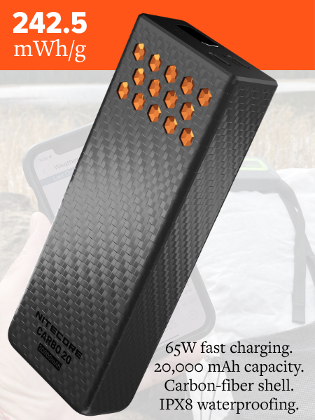 Carbon Fiber Power Bank20,000 mAh power bank with a lightweight carbon-fiber shell.
 Loading...