Topic

Engineering the V4 Winter Stove


Forum Posting

A Membership is required to post in the forums. Login or become a member to post in the member forums!

Home Forums Gear Forums Make Your Own Gear Engineering the V4 Winter Stove

Viewing 25 posts - 1 through 25 (of 77 total)
  • Author
    Posts
  • #3652888
    Roger Caffin
    BPL Member

    @rcaffin

    Locale: Wollemi & Kosciusko NPs, Europe

    This is an experiment with a sort of a blog. Will it work?

    Back in 2007 I was using a Coleman Xtreme (remote inverted canister) stove for winter XC ski tours. It was a good stove but it was a shade heavy.

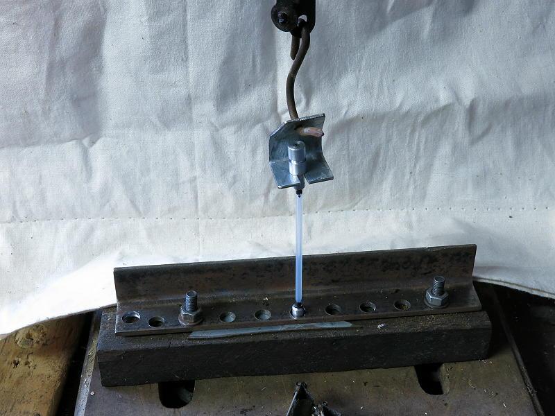
    Then I was sent a Brunton Stove Stand for review. I tested this with a Snow Peak GST-100 upright, and that worked fine. But it was only for ‘upright’ stoves, and could not be used with an inverted canister. I started to wonder whether some sort of heat shunt could be used with this stove stand to let me invert the remote canister. I tested the idea and it worked.

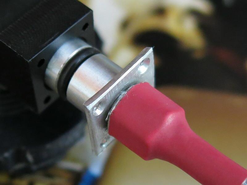
    A Heat Shunt is a strip of thermally conductive metal going from the flames to the fuel inlet. It replaces to fuel tube going over the top of the flames. In this case it was enough to vaporise the liquid fuel so the stove ran well. “Hum, interesting” – and so the saga began.

    The first step of course was to replace the Brunton Stove Stand with its heavy steel legs with something lighter.

    A Snow Peak GST-100 on my own base and legs, with an early version of my canister connector. It was a start.

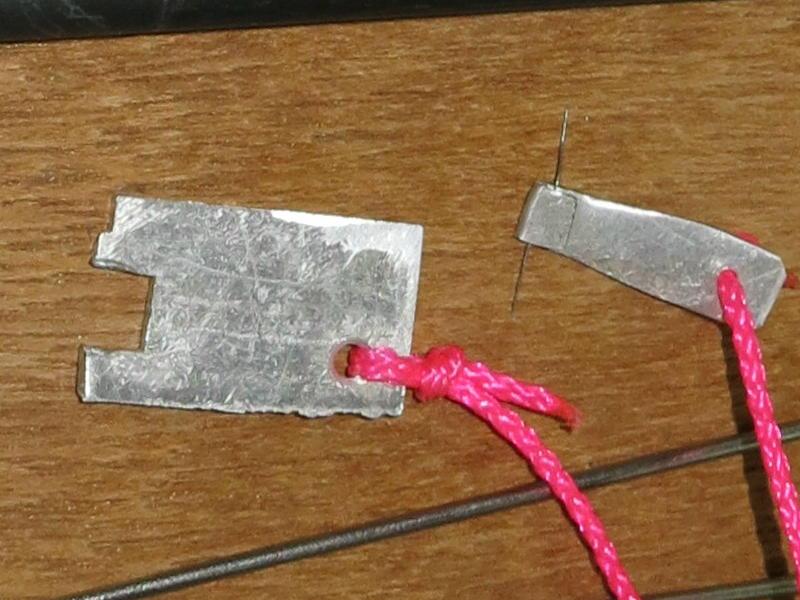
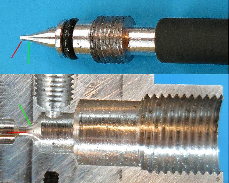
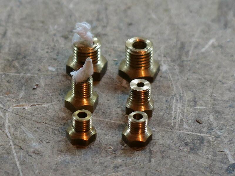
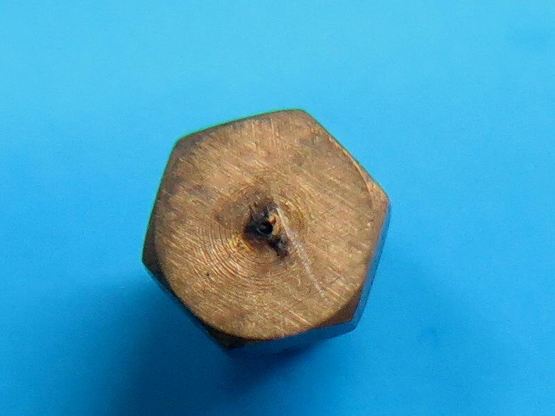
    At the same time I had had stove problems on one of our 2-month-long walks along the European Pyrenees. I had been using brand name screw thread canisters with my much-loved Snow Peak GST-100 stove. The harsh jagged steel screw-thread was ripping off the brass thread in the stove, to the point where the stove would no longer reliably connect to the canister.

    The result (the one on the right) was quite safe: the stove could not open the Lindal valve anymore, so no gas came out.

    But that also meant no hot coffee or hot dinner that night. I had to buy a new stove at the next town if we wanted to eat. I could not find any light screw-thread stoves for sale in the little villages up in the mountains: I was lucky to find a rather lumpy and heavy Campingaz one. At least we ate again.

    When we got home I decided ‘something had to be done’. The concept grew (of course): what I wanted was an MYOG canister connector able to handle screw-thread canisters, (French) Campingaz canisters and Coleman Powermax canisters. It would be convenient to be able to handle the screw-thread canisters anyhow; often the only canisters I could buy in the Pyrenees were Campingaz ones with their different connecton, and I still had a lot of those lovely Powermax canisters full of fuel at home. I quite emphatically did NOT want a screw thread connection again.

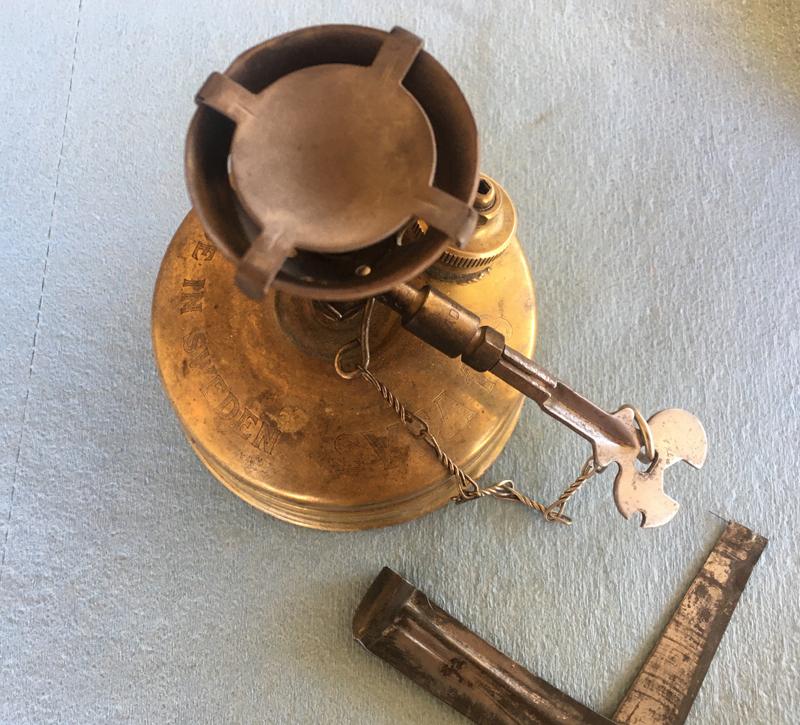
    The obvious next step was to have a light flexible hose from the canister connector to the stove.

    I did not want an axe-handle for a hose. If nothing else, I think those rigid hoses are dangerous.

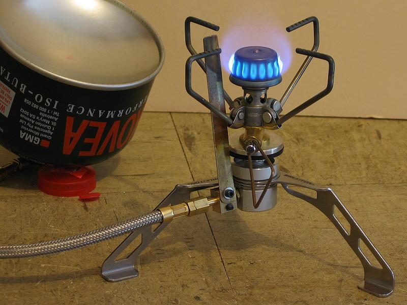
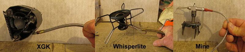
    Given my experience with the Brunton Stove Stand and the follow-on version, I saw no reason to have a great big pipe over the top of the burner for preheat. It may be required on an XGK stove burning kero (well, it IS required), but not on a stove burning butane/propane.

    There was a lot of thinking, sketching and some experiments. Wonderful theoretical fun times. They are history now, but they did lead to the V1 Remote Inverted Canister Winter Stove. I had sorted out the canister connector and the hose by this stage, and I spent a LOT of time playing with different burner heads for this but I was never satisfied.

    My impatience led me to use the burner head off a commercial stove instead.

    I published some articles about this , and found that hordes of BPL readers wanted one. I had to do a bulk-buy of light Korean upright stoves direct from the manufacturer (100 off) for the production. I ended up selling well over 100 of them, and endearing myself to the local Post Office.

    After that I returned to the problem of devising a burner head, and did a fair bit of development work. However, somehow I got diverted into the fascinating world of Vortex Burners. They are very different. After a lot of experimenting with splash plates, internal air flow and their interactions, I came up with V2 and then V3. I sold both of them.

    Eventually, while cleaning up, I found the half-complete test units (burner heads) in the cupboard -sadly neglected and abandoned. They were better than I had remembered, so I returned to the idea of making my own. Obviously there were lots more experiments, leading eventually to V4.

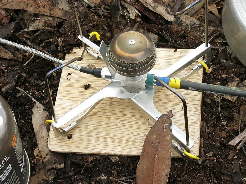
    It was not just the burner head that had to be developed, but also the stove legs or pot supports. However, I did retain the well-developed canister connector and hose.

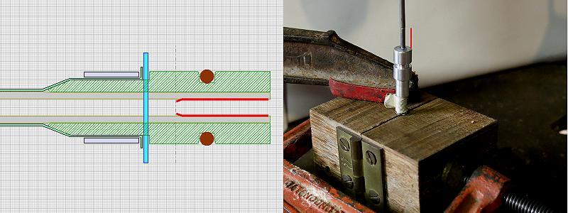
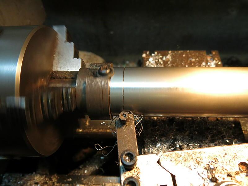
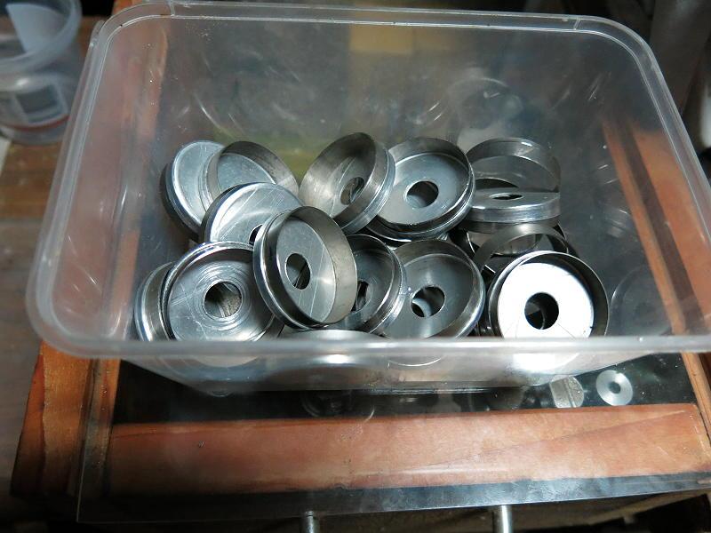
    I make most of the parts for my stoves on my CNC machine


    so I had to develop and test all the programs needed just to get one V4 stove ‘right’. Inevitably, that meant I had to make a small number V4 stoves with the final versions of the programs, just to confirm that they were ‘right’. However, once the V4 articles were published
    [https://backpackinglight.com/diy-ultralight-remote-inverted-canister-winter-stove-version-4-part-1/]
    [https://backpackinglight.com/diy-ultralight-remote-inverted-canister-winter-stove-version-4-part-2/]
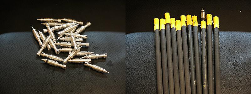
    my small existing stock was quickly snatched up. Despite my warning would-be customers that there would be a manufacturing delay before I could ship, they continued to send me money. Having accepted the money, I now had to make more stoves.

    Then COVID hit, and readers were restricted to their homes. The supply of interesting Trip Reports and Gear Tests dried up. Life became rather boring and bland. So I thought there might be some
    interest in a sort of blog describing how the V4 stoves are actually being made. Well, it would be better than staring at a blank wall. Hence, this ‘blog’. You can expect updates every few days as different parts are made, but there are no fixed dates.

    #3652915
    Jon Fong / Flat Cat Gear
    BPL Member

    @jonfong

    Locale: FLAT CAT GEAR

    Nice Blog!

    #3653234
    Adam Kilpatrick
    BPL Member

    @oysters

    Locale: South Australia

    Looking forward to seeing what you come up with and test next Roger

    #3653270
    Roger Caffin
    BPL Member

    @rcaffin

    Locale: Wollemi & Kosciusko NPs, Europe

    Parts list for V4

    I did a break down of the V4 to major components, going from one end to the other: Canister Connector, Hose, Stove Body, Burner Head and Pot Supports. When I listed out all the parts needed, I found I had about 46 lines in the spreadsheet. To be sure, the list includes things like O-rings and small screws, but that is an awful lot of parts! It sort of creeps up on one.

    Baseboard
    Micro-stakes set of 4
    Pricker & Spanner
    Blue screw driver
    Legs set of 4 Al
    Legs set of 4 wires
    Burner Tube
    Burner head Al base
    Burner Ti ring
    Burner Head formed mesh
    BH Top Cap
    BH Inner Cap
    BH Deflector
    Heat Shunt
    Stove Body
    Needle Valve
    CF tube handle w heat shrink & wire
    Heat Exchanger rod
    Jet
    PFA hose
    SS braid
    Hose Lock Nut stove end
    Hose core fitting stove end
    Hose 8 mm connector
    Lock Tube 2 off
    Retainer plates 2 off
    Crimp rings set of 2
    Heatshrink 2 piece
    Self tapper screws 6 off
    3.0 x 1.5 O-ring hose end
    5.0 x 1.5 O-ring Canister conn
    7 x 3 O-ring Nipple seal
    4 x 1.5 O-ring needle valve
    Canister Connector body
    Connector safety valve
    Connector valve handle
    Connector Spider
    Main Ring
    Valve actuating pin
    Valve pin retaining washer
    Ti leg support washer 22 mm 2 off
    Ti leg clamp washer 14 mm
    Brass friction washer 22 mm 5 off
    Slotted disk spring
    M3 SS grub screw 9 mm long
    M3 SS nut

    Fortunately I had kept fairly extensive notes while making the first batch of the V4 stoves – without good documentation one is simply dead in the water. Or one has to completely reinvent the whole thing next time. Also, I had a whole disk folder of reasonably well-developed CNC routines for each part, plus a shoe box of developed jigs needed for holding the parts for machining. A little polishing and they were good to go – one at a time. Documenting this process could now be fun.

    I decided to produce the parts needed in batches of limited size. This would make the manufacturing go a bit faster, partly so that my existing customers would get their stoves sooner, but also because there was no point in making 100s of each part if I did not need them. OK, and the materials used did cost money too. I rely on this stove myself: I decline to make it on the cheap.

    As I said above, a lot of this is being done on my CNC machine. There are two reasons for this. The first is that making the parts on an automated machine is a lot faster than making them by hand. I can sit back on a good chair and watch the machine purring away – even with my eyes shut. That can be quite satisfying in its own way. If anything goes wrong, I will hear it very fast: I don’t need to be looking.

    The second reason is that desirable thing called quality. I can drive my little manual lathe to about 0.1 mm if I am careful, and my mill to maybe 0.05 mm. Beyond that the leadscrews and backlash place real limits. But some of the parts in the stove need better accuracy than that as we are dealing here with propane and butane under high pressure and in the presence of a flame. Leaks are not invited! (Stove accidents? Who, me?) With my CNC machine I can have accuracy better than 0.01 mm (10 microns), continuously and without effort. That is good enough.

    Expanding on the above, the following major parts or sub-assemblies have to be made. I will list them here, and then in following blog postings here I will cover how each of them has been made. The details won’t be in the order shown here but as they are made. I hope the details won’t be boring. At least there will be pictures.

    Canister Connector: a major part with lots of components
    Hose: the braided hose itself, the fittings at each end, and how it is assembled
    Stove Body: a single part, but machined on all sides and ends, which is complex
    Needle Valve: a single part but tricky to get really right as it is so thin
    Heat Shunt and Heat Exchanger: very simple parts, but very essential
    Jet: small and fairly simple, but with that tiny 0.3 mm hole to be drilled
    Burner Head: no less than 8 parts make this, all of which had to be extensively ‘tuned’ for a good flame over a wide range of power
    Stove Legs & Pot Support: machining and bending, with tricky joining the two

    In the next posting I will get into the actual MYOG stuff, with explanations as to how and why.

    #3653281
    Kevin Babione
    BPL Member

    @kbabione

    Locale: Pennsylvania

    This is a great post (It reminds me of the original Moulder-Strip thread) so thank you.  One stupid “Yankee” question for you:  The third item in your BOM is a “Pricker and Spanner”.  I know a spanner is (at least to me) a wrench, but what is a “pricker”?

    Thanks for the translation help!

    #3653378
    Roger Caffin
    BPL Member

    @rcaffin

    Locale: Wollemi & Kosciusko NPs, Europe

    Hi Kevin

    Ah, you have obviously never used a kero stove. :)
    The pic here shows both the ‘spanner’ and the pricker.

    The spanner fits the jet and is is deliberately very short, to limit the torque the user can put on the jet thread in the stove. Stripping that could be dangerous.

    The pricker is a small (Al) handle with a fine wire crimped into the end. The wire is LESS than the size of the hole in the jet. It is used to clear dirt and stuff out of the jet hole so the gas can flow. Sadly, we know that some canisters do have fine dirt in them. I won’t buy Chinese canisters any more.

    Cheers

    #3653383
    Nick Gatel
    BPL Member

    @ngatel

    Locale: Southern California

    I like how this was done. Can you do something similar with yours?

    #3653395
    Roger Caffin
    BPL Member

    @rcaffin

    Locale: Wollemi & Kosciusko NPs, Europe

    Hi Nick

    Yeah, all very nice, but . . .

    I am not going to provide a long spanner. The Svea one shown is for getting the nut off the needle valve, and I can understand that some torque could be needed there. But I do NOT want much torque applied to the jet because it goes into an aluminium thread in the stove body, and the aluminium is not as strong as hard machining brass. The jet seats against an aluminium shoulder which seals very well at limited torque.

    The Svea pricker is a nice bit of stamped sheet metal, but I do not have a stamping machine. I have to make the prickers by hand. Also, I did not want a long sheet metal handle because that would be too big and bulky for my taste. I do sheath the end of my pricker in a bit of folded light cardboard for protection of the 0.25 mm wire and store it in a tiny zip-lock bag. (The jet is 0.30 mm diameter.)

    Now this may sound very negative, but it really is not meant that way. The bits shown in the photo above are the ones I have been using for a number of years (5+) in the field. They work just fine, even if they do look a little ugly. By careful selection of what brands of canisters I use, the tools do not see all that much use.

    Of course, this is just what I supply. The buyer is free to make up his own spanner and pricker if he wishes. Plenty of room for artistic creation! Photos of implementations would be appreciated.

    Cheers

    #3653402
    Kevin Babione
    BPL Member

    @kbabione

    Locale: Pennsylvania

    Thanks Roger – the photos really help!

    #3653679
    Roger Caffin
    BPL Member

    @rcaffin

    Locale: Wollemi & Kosciusko NPs, Europe

    The Hose

    This segment should have been quite short: it’s just a hose after all. But somehow, it did not turn out that way.

    I need a hose with a very reliable gas-tight lining, able to take propane at high pressure, and a reinforced metal sheath. Actually one could possibly do without the sheath, but it does add two sorts of safety. A metal sheath resists high temperature and resists abrasion: these are good things. Also, if the metal sheath is anchored to the fittings at each end, it adds strength to the hose.

    I have in fact tested the connection between the hose and the end fittings without the sheath. I will explain the details later on. The connection took up to 7 kg of force without failing. That is huge compared to the blow-out force due to the pressurised gas, and huge compared to the weight of the stove or canister.

    The sheath is crimped to the end fittings with considerable force. That connection has also been tested and will take >7 kg of force. The crimping, which took a bit of development, will also be explained later on.

    I have heard of a stove hose which used some sort of cheap black rubber tubing as the core. The rubber perished, shedding little bits of crumbling stuff, which threatened leaks everywhere and also blocked the jet. Oh great!

    One can buy tubing able to take propane with a 1/8″ core of a suitable material and with a tightly braided metal cover, but it is like the hose you see on many commercial stoves: as rigid as an axe handle. It is also too large: it has a 1/8″ core ID, which is way over-kill and wastes gas when you run the stove off. There is a good reason for the rigidity: that hose is made as a fuel line for the race car industry. For that they want a hose which will not bend or flap at high (engine bay) temperatures while the F1 car is doing >200 mph on the track. I can understand that. But that does not make it suitable for a little light-weight canister stove; it just means the stove companies can buy it by the reel.

    One can also buy small-bore hose made for the fuel supply for little 2-stroke engines (mowers etc). It is nice and flexible, and at room temperature has an adequate pressure rating for propane. It is also readily available and cheap. I tried some, and it was fine, until it got a bit warm at the stove end. The soft hose ended up with a solid imprint of the covering braid: the effect of medium warmth. Definitely not good enough!

    So I decided to make my own flexible sheathed hose. I decided to use the best hose I could find, which meant choosing between PTFA, PFA and FEP from a major American manufacturer. (Well, there was nothing on ebay at the time.) These materials are all chemically inert, tough, strong and able to take temperatures over 250 C. By choosing a small bore (1/16″) for the tubing, it could also take over 400* psi (2700 kPa) at room temperature, and over 100* psi (690 kPa) at 200 C – without the braid reinforcing. It could also work down to -196 C, although I have no intention of ever testing that! I chose the PFA: it has slightly better specifications than the other two.
    (* A safety factor of 4x is included here, above the quoted figures: excellent.)

    Could one use a silicone tubing? It is after all readily available. Unfortunately, the silicone polymer is slightly porous to propane, and industry recommendations are against it. You would not want little flames dancing along the hose, would you?

    Then I needed some metal braid to cover the hose. Copper braid is easy to find, but it is not strong and will crack after a bit of flexing. I went for stainless steel. I found a manufacturer in Taiwan who could make what I wanted to my specifications. The first reel (‘original’) was excellent. I ran out after a while so I ordered a second reel to the same specifications. Unfortunately the minion who made it for me at the Taiwan factory did not read the specifications properly. The new braid (1st new batch) was not suitable: you could not get the hose inside it as it was woven too tightly.

    I emailed the company with the top two images in this photo, they apologised, and made a new reel (replacement) to fit the hose – at no extra charge. One cannot complain. The ‘replacement’ lot does not look exactly like the original lot: It has been braided a bit tighter. That’s fine of course.

    In both versions there are small daylight holes between the individual wires, but that is useful. You can see the liquid fuel flowing down the hose through those gaps. The only trouble with the braid (both lots) is that it comes ‘stretched out’. This is fact inevitable. I have to compress it lengthwise as illustrated by the ‘1st new batch’ before I can get the hose into it. A fiddly and tedious job, but straight forward. The paper tape at the ends in (C) below prevents the braid from unraveling during handling.

    Next posting we go into the details.


    #3654074
    Roger Caffin
    BPL Member

    @rcaffin

    Locale: Wollemi & Kosciusko NPs, Europe

    The photo below with labeled parts shows how the bits go together. Any letter refers to this.

    The fitting at the canister end is an 8.0 mm ‘plug’ with an O-ring.
    Current production is shown here.

    This part (D) fits into the matching 8.0 mm bore in the canister connector (as shown in A), and can rotate in place. You need the rotation because the hose seems to have a permanent curl to it. The PFA hose goes inside the plug in a tight-fitting hole and is secured there by an over-sized sleeve (hypodermic tubing, G) forced in the end. The braid goes over the right hand end of the plug (D) and is secured there by a bit of tubing (F) crimped hard over it. The result looks a bit like the crimped fitting on the end of a coaxial cable, and in fact that is where the crimp tool comes from. Once crimped in place, this connection is strong.

    The plug would of course blow straight out of the canister connector if not held in place. That is done with a small retainer plate (E) fitting over the braid, secured to the canister connector with some self-tappers. The heads of the self tappers can just be seen at the plates in part A. The hoses (B) also show the retaining plates at the left end.

    This photo shows the retaining plate in place, the O-ring in its groove, and the fitting going into the canister connector. The holes drilled in the canister connector for the self-tappers are only just big enough for the thread: that gives them a good holding power. Testing for the right sized hole was done with a series of drill bits in steps of 0.05 mm.

    You will see 4 holes in this photo, but I only use 2 of them. The other two are there ‘in case’ the thread in the plastic gets stripped and no longer hold the screws. It has only happened once so far.

    The hose at the stove end also has to rotate, because of the usual curve in the hose. For this I made an aluminium sleeve which fits over the hose and has a shoulder.

    The hose again goes up inside this part H and is locked in place with a similar bit of hypodermic tubing (G). I’ll come back to that later. It is locked onto the stove body with a special nut (J) which butts against the shoulder on part H. In this case the sealing O-ring (not shown) is a bit smaller and goes over the PFA hose itself.

    As mentioned above, the mechanical strength of the connections was tested to 7 kgf.

    Also tested was the sealing of the hose inside the metal fitting. For this I submerged the hose and used compressed air at a shade over 100 psi – which was as much as my compressor could provide. Zero leakage (bubbles) was mandatory. You can’t see the rotating core in this photo, just the lock nut which holds it in place. That’s the shiny bit just south of the red heatshrink.

    Actually, this photo was originally meant to illustrate testing the jet on one of my Vortex Burners: note the ‘fog’ of spray coming out of the jet at the right. To properly test the hose connection at full pressure I simply shut off the control valve so no air reached the jet. That case looked too ‘boring’, so I did not photograph it.

    Finally, just for decoration, the crimp rings at each end were covered with a bit of heat shrink (yellow, red or blue, A & B). It reinforces the bit of the hose coming out of the fitting, not that it is likely to kink there. It also masks any stray bit of the braid which might be sticking out.

    Now, back to that tiny bit of hypodermic tubing. Is it really necessary?
    Well, actually, yes, absolutely. Without it the hose would leak gas at
    both ends.

    This shows an engineering drawing on the left of the hose fitting (green hashed) with the PFA hose (grey) up inside it, and the hypodermic tube in red inside the hose. On the right is a photo of how the tube (next to the red line) gets inserted with some force into the hose.

    Now ask how does the hose get into that (green) fitting? The hole in the fitting has to be slightly larger than the hose for clearance, and that clearance will leak propane. So the red bit of hypodermic tubing forced into the inside of the PFA hose expands it outwards to press tightly against the bore of the fitting, making a gas-tight seal.

    You will note a taper at the left end of the red tube in the engineering drawing. This taper is why it works: without that taper the tube would just plow through the PFA without pushing it outwards to seal inside the bore.

    I did try to get these bits of hypodermic tubing made for me in bulk, but without success. Companies were willing to cut off the bits of tube and smooth over the ends (by tumbling) but none of them could add the taper. So I had to make them myself in my manual lathe. Tedious, but effective.

    The photo on the right above shows the hose clamped tightly in a wood block,  with the tube being pressed in. The hole down the joint in the tight wood block can hold the braid and the hose effectively. It’s no use trying to hold the metal fitting instead of the hose: the hose just gets pushed out the bottom.

    #3654472
    Roger Caffin
    BPL Member

    @rcaffin

    Locale: Wollemi & Kosciusko NPs, Europe

    Needle Valve

    The needle valve is long and thin. It has a pointy tip which goes into a valve seat to regulate the amount of fuel going through, an O-ring for sealing the gas in, a threaded section for controlling the valve position, and a handle for the user to turn.

    When discussing the needle valve, it helps to have in mind the body it
    goes into. The point of the valve, pointed to by the red line in the top half, goes into the valve orifice (red line, lower). The actual throttling and shut-off is done by the shoulder (green line, upper) hitting the valve seat (green line, lower). The O-ring and the threaded part are obvious. (The cross-section here is still slightly wet, hence the spottiness.)

    The gas comes in at the left, passes through the valve seat, and goes up to the jet which is screwed into the vertical threaded bit. The O-ring stops the gas from escaping past the thread.

    The needle valve actually works out fairly long and thin, and that means it can flex a bit when being machined. Such flexing is most undesired, as the dimensions around the tip are critical. To hold the flex to a minimum the needle is machined in two stages. At first only a short bit of rod sticks out of the chuck as the tip is machined (left). With that critical bit done, then the thread is machined (right). This is done with gang tooling on the CNC: the machine switches automatically (well, under program control) between the two cutting tools shown here. Trust me, such automation makes life much easier.

    Later the blank is moved out a bit under program control so the rest of the needle (the handle section) can be machined. Finally, the whole needle valve is parted off.

    Eventually you end up with a heap of needle valves. The handle end of each one has a slot machined in it (visible in the front needle). This is a manual process with a slitting saw but with a fixed set-up on the mill table. The fixed set-up gives uniform results.

    Then some carbon fibre handles are made, with heatshrink at the end for protection of the end of the tube and for visibility (when you drop it in the grass). A hole is drill through both sides of the tube using another jig, and a bit of wire is put through the holes and the ends bent over to lock it in place. This wire drives the slot in the needle handle.

    Attaching the handle is then very simple: push the tube over the end of the needle valve handle and rotate until the wire engages with the slot. To remove, just pull. That makes packing the stove up very much simpler.

    A final note. The needle valve is a CONTROL valve; it is not meant as a fail-safe shut-off valve. For real safety you have to use the on/off valve in the canister connector. That is guaranteed.

    #3654476
    Nick Gatel
    BPL Member

    @ngatel

    Locale: Southern California

    This is fascinating and impressive so far, especially the planning and the CNC machining.

    #3654477
    Roger Caffin
    BPL Member

    @rcaffin

    Locale: Wollemi & Kosciusko NPs, Europe

    Thank you Nick.

    Cheers

    #3654572
    Roger Caffin
    BPL Member

    @rcaffin

    Locale: Wollemi & Kosciusko NPs, Europe

    Why am I doing this?
    +4 C in the morning, and the workshop is a large unheated galvanised iron barn with plenty of open eaves.

    Cheers

    #3655195
    Roger Caffin
    BPL Member

    @rcaffin

    Locale: Wollemi & Kosciusko NPs, Europe

    The Jet

    The jet is a simple little thing, no problem at all. Well, ‘mostly harmless’.

    This shows some development work with different sized jets. I was trying to get some sort of filter into the back end of the jet to catch any muck and garbage flying along. About all I succeeded in doing was to create the equivalent of a significant blockage of the jet. The little bit of tissue paper was too opaque to the gas flow. So I ended up with the smallest of the jets sizes.

    I should add here that some upright stoves have a sintered filter where the tissue paper goes. That is the squashed (‘sintered’) mass of little balls in the unit at the left. This does not present as much of an obstruction to the flow of the gas – at first. Of course, once a little dust and wax has been intercepted by the sintered filter, the filter is blocked and the stove is dead. You can’t get that filter out to wash it clean. You can see some patches on the sintered mass already. The road to hell is paved with good intentions.

    The jet on the right is minus its sintered filter. I drilled it out and put the jet back in the commercial stove it came out of. Now it runs unfiltered. Oh well, never mind. Hopefully most of the fine dust and wax will blow straight through the bare hole.

    Machining the jet body is done on the CNC with gang tooling. The shape of the jet uses one tool tip, the thread uses another tool tip, and the 2 mm clearance hole up the middle uses two tools: a centre drill bit and a short 2 mm drill bit. You need to start with a very rigid centre drill to establish a guide hole. Without that the thin 2 mm drill bit can wobble instead of drilling.

    Now, the whole point of this great big lump of brass is the tiny hole in the middle. That hole is where the gas comes out; its size is a crucial factor in the performance of the stove. In fact, the power rating of the stove is largely set by the size of the jet hole. The actual design of the burner head does not really affect the power rating, although it does control the flame shape. However, the tiny hole is not drilled in the CNC by the 2 mm bit.

    This is the top view of a used jet. If you look very closely, at about 9 o’clock you can see a bit of something blocking the hole. This happens, which is why I provide a ‘pricker’ with the stove, to help clear out any blockages. Bearing mind that the hole is 0.3 mm diameter, I had to use a few tricks to get this photo. This hole is tiny.

    So, how is the hole drilled? You can not just put a 0.3 mm drill bit in a chuck and expect to get a good hole. In fact, with many chucks all you will get is a broken drill bit. Most (affordable) chucks are not that good: the drill bit is never that concentric with the axis of spindle rotation. A chuck can be off-centre by 0.1 mm – which is huge compared to a 0.3 mm bit. One has to be cunning.

    If the chuck holding the drill bit is not all that concentric, then don’t rotate the drill bit at all. Instead, mount the jet on a little (custom) jig in the chuck of the manual lathe and spin it. But surely that means the jet may be spinning 0.1 – 0.2 mm off centre? Well, yes, but so what? The internal diameter of the burner tube is about 9 mm: having the hole in the jet off-axis by 0.1 mm hardly matters. The hole in the back of the jet is 2 mm: also large.

    The drill bit is held in a precision chuck which is mounted on the saddle of my manual lathe via a precision vertical slide (taken from an optics bench). The lathe cross-saddle itself can align the bit on the horizontal axis, while the vertical slide positions the bit on the vertical axis. With a head-mounted magnifier I can line up the tip of the drill bit with the centre of rotation of the jet body, and drill a hole – gently.

    I usually use a micro-centre drill bit first, to make a guide ‘hole’ or dimple for the 0.3 mm bit. Swapping the two bits only takes a few seconds. Since implementing this set-up I have not broken a drill bit – which is nice because they are very expensive! Swiss, and made for watch-making.

    #3656395
    Roger Caffin
    BPL Member

    @rcaffin

    Locale: Wollemi & Kosciusko NPs, Europe

    Dear me – a long gap in time without an update. Sorry about that. I was busy, as follows.

    Burner Head

    The burner head is where the Version 1 stove wimped out (or maybe I wimped out?). I was not happy with any of the models I tried, so I resorted to using a commercial burner head taken off a commercial stove. That worked, but it left a gap so to speak.

    Coming back after V2 and V3 to the experiments I was doing after V1, I found a box of parts which were very near to finished. Just … not quite. Well, actually, I was tidying up when I found them. Peers into box and says ‘Good lord’.

    One major problem with what I had done so far was the way the old heads were put together. The assembly process involved spot welding stainless steel (SS) foil (inside the head) to stainless steel mesh to titanium alloy. Spot welding SS to SS is fine and works well, but spot welding anything to titanium is doubtful. So says all the research.

    The photo here shows a spot-welded head. What seems to have happened with the spot welding on my burner heads was that both the SS and the Ti got soft and sort of squooshed together under pressure, but there was no actual merging of the two metals. A serious poke and the Ti cap could fall off the SS mesh. It did take quite a serious poke to do this, but I did not want the top of the burner head falling off in the field in two years time, or even the risk of this happening.

    A second problem was that I was still not really happy with the design of the insides of the head. I went into what is going on there in one of my V4 articles. It was all a matter of getting the gas flow inside the burner head right. The original inner deflector was often just not quite good enough. Some units seemed to work OK, but other units did not, and I did not know why.

    The end result was that I decided the burner head needed a major work-over. For that, I needed to understand what was really controlling the gas flow inside the head. That took many weeks of work, making up test units and discarding them. Aerodynamics on a micro scale is ‘not obvious’. I will skip a lot of the details.

    The point of the internal deflector is to control the direction of the gas flow coming out of the mesh/head, and hence the direction of the flames. Without any deflector in place, the flames tended to come out pointed slightly downwards, almost away from the pot. That has all sorts of bad things going for it. With the deflector in place the gas does hit the inside of the mesh while going substantially upwards, so the flames go upwards.

    Ah, but I did not want the flames going straight up, because when they did they tended to curl over the middle and heat up the Ti top cap to red heat. That does not hurt the titanium top cap, but jumping ahead a bit it risks melting the aluminium pop rivet which holds all the top assembly together. The pop rivets are very small, and only aluminium ones seem to be available in that size: no steel or monel ones. So I needed to keep the top cap from showing any sort of ‘glow’.

    Another problem was that the flames were OK at low power but they went a bit ‘starved’ at high power. Not enough air was being sucked in. What was inhibiting the flow? If I removed the deflector the flames were short at all powers, so the air inlet holes were big enough. Eventually I realised that the gas flow had to be ‘hitting a wall’ at the top of the burner head and making ‘back pressure’, at least at high flow.

    I found that if I changed the top of the burner tube to have an outwards taper (to help the gas expand) and if I changed the dimensions of the deflector to be a bit bigger at the top, the air flow sorted itself out and the flames were good. In addition, the deflector was now tapered rather than ‘square’. You can see this in the drawing above.

    At the same time I realised why the top cap was getting so hot: the flame was too close to it. I solved this by putting an Inner top cap (blue) inside the mesh, one with a larger diameter. That kept the flame away from the Ti top cap (green). Since the mesh was keeping the flame outside the burner head, this second inner top cap could be made of very light stainless steel foil.

    Finally, I found that I had to control the gap between the top of the Ti ring and the edge of the inner cap (red line). If this gap was too small the speed of the gas coming through the mesh at high power threatened to exceed the ‘flame propagation velocity’ such that the flame started to lift off the face of the mesh. This can be dangerous. If the gap was too large the flames sort-of went everywhere.

    More to follow.

    #3656978
    Ken M
    BPL Member

    @kenmoz

    Locale: Louisville, Oh

    Roger,

    I’ve really enjoyed this thread and would like to say —Thank You— for posting it. I can appreciate how much time you must have spent just documenting the story let alone how much effort (and frustration?) it takes to prototype and improve a design. But then again, that’s where the fun is isn’t it?

    I come from a background of tool and machine design and have had access to CNC equipment and skilled machinists. I envy your small CNC setup. At home I have a small manual lathe/mill combo. I have endeavored off and on to build a small (light) white gas burner with a micro pump. I’ve never quite mastered the skill for those small internal threads…or those .3mm holes! Maybe I will be inspired and dig out that box of experimental stove parts?

    Thanks again for posting this lengthy thread.

    KenM Louisville, Ohio USA

    #3657055
    Roger Caffin
    BPL Member

    @rcaffin

    Locale: Wollemi & Kosciusko NPs, Europe

    Hi Ken

    Long LONG ago I did try doing that (for kero), but I did not have the tooling needed. Since then I have switched to propane/butane and once I made the switch I have never looked back.

    Small internal threads: I thread-mill them down to about M4.5. Below that in aluminium I use a thread-forming tap (M4 and below). The secret there is to get the right size hole first. It has to be bigger than the normal tapping hole size to allow room for the metal to move. But I don’t try in steel or hard brass: they don’t flow well enough.

    Cheers

    #3657513
    Roger Caffin
    BPL Member

    @rcaffin

    Locale: Wollemi & Kosciusko NPs, Europe

    The Burner Head, Continued

    The mesh itself was formed with a die. It uses 40 gauge stainless steel mesh, where the 40 refers to the number of wires per inch (I think). The thickness of the wires themselves mattered a bit. I started with some fairly heavy mesh using stuff I had in stock, but then moved on to some slightly lighter mesh from ebay. I found the lighter mesh (still 40#) formed rather better, so I have stuck with it.

    I had to start with a tightly-controlled circle of mesh before it was formed into the dome. If it varied in diameter the dome did not always work properly. The need for tight sizing was the same for the deflector material and the inner cap. Some galvanised steel circles of exactly the right size made cutting out lots of parts easy.

    The rest of the burner head was more straight forward. The aluminium burner tube was turned and threaded on the CNC lathe. The four holes were machined through the side of the tube on the 4th axis on the mill: that’s a device for rotating the unit, shown here.

    Forming the inside parts was interesting. The Ti top cap and the inner cap are simple enough: a flat disk with an edge curled up a bit. The curl around the rim does make the part much stiffer of scourse. The deflector was another matter. The shape involved quite a bit of press-forming. I was able to make the part using 0.03 mm stainless steel shim and with 0.3 mm aluminium foil. I had to very lightly grease the inside of the female die to let the metal slide over the surface and wrap around the male die.

    I started with the SS foil shown (because I had it) and then moved on to the Al foil. The Al foil compressed better than the SS – surprise (or not)! But even so, the 0.3 mm Al foil was a shade flexible, and I did wonder whether I could change to something stronger – like fairly hard 0.5 mm Al foil. So I bought some and tried it out. The part on the right here is made with the 0.3 mm foil, and is fine. The part on the left used the 0.5 mm foil – and it was not successful. You can see where the male die (shown) was pushing the aluminium into the female die (those creases around the edge), but somewhere along the line the stiffness got too much. Rather than further deform around the die, the end part was stretched to the breaking point and then punched out.

    Cutting off the Ti ring for the burner head in a controlled fashion was not easy: that took a mandrel in the lathe chuck and a 3-point steady at the other end of the lathe bed. It also took a sharp bit of High Speed Steel to cut the titanium in a determined fashion.

    The aluminium base to the burner head started out as a circle of sheet metal which was then spun over the Ti ring on the previous mandrel so that the ring was tightly held. This used a ball bearing as a roller.

    This results in a stack of burner head bases, seen here. Once set up, I make a number of them together of course, as setting up always takes a lot of time.

    Then the base is force-fitted to the top end of the burner tube. A couple of correctly sized ‘dies’ mounted in a strong drill press does this. The photo here completed burner heads at the back, then a row of partial burner heads: tube plus base, and at the front there some stacks of the bits used to make up the mesh assembly: inner caps, Ti top caps, deflectors and a Heat Shunt.

    Finally the various bits of metal were pop-riveted together to make the mesh assembly and the mesh was squeezed at the edge to fit into the Ti ring. That was not as easy as it sounds: the little ends of the mesh wires love to stick out and get caught on the edge of the Ti ring. In the photo here the mesh assembly is still held together with little M2.5 bolts, while I was checking the results. (Also, I had to buy some more of the pop rivets.) Just replace the Phillips head with a pop rivet in your mind.


    #3664639
    Roger Caffin
    BPL Member

    @rcaffin

    Locale: Wollemi & Kosciusko NPs, Europe

    A few more details for anyone interested. The top cap (second left) is made of a ‘soft’ titanium: it is called Commercial Purity or CP. It is much easier to work with than the 6Al4V titanium alloy. But at 0.3 mm thick it is still hard to cut very well, so I decided to stack a lot of the flat disks up and turn them to the required diameter in the lathe. That was less easy than it sounds.

    The problem is that the hole in the middle is only 2.5 mm, and a bolt of that size does not have much holding power. Also, when maching a stack of them, the ones at the end of the stick tend to bend over a bit and go all horrible. It was difficult.

    The stainless steel inner caps (left) use shim of 0.06 mm thickness, and these I cut out by hand. I used a steel template over the top as a guide. Then both the Ti outer caps and the SS inner caps were put into a die set and pressed into shape one at a time: about 4 tons force was used.

    Then circles of SS mesh were cut out, again using a steel template guide. These are second from the right. The mesh was put into a different die set and shaped to the dome.

    Finally, we have the defector thing which goes inside. This is made of 0.3 mm soft aluminium foil. A circle is cut out, place in a die, and press-formed. The difference in this case is that the shape is not ‘flat with a curl at the edge’, but a deep drawing. The flat circle gets crumpled up as you can see here, but the hydraulic press manages to hide the wrinkles – mostly.

    The steel die set is at the outside; the newly pressed bits are at the middle left, and at the middle right we have the deflectors after the crinkly rim has been trimmed off. The creases are visible, but not very. A hydraulic press exerts a lot of pressure.

    Press-forming is not always simple, even with soft materials. If you get the details wrong you can get rips in the soft material. I will add that you can also get rips in very hard material if you want.

    Finally the whole lot are stacked up on a small 2.5 mm pop rivet and the rivet is set with a gun. You can’t see the pop rivet: it is inside the steel tube I am using to hold all the bits tightly together. You can just see a tiny SS washer sticking out at the bottom of the tube: it is there for the pop rivet to bear on because the soft aluminium parts are just not strong enough.

    Some light relief. Cutting out all these circles from squares generates some swarf, or left overs. Care is needed here: all these corners and edges are sharp!

    #3664675
    DAN-Y/FANCEE FEEST
    Spectator

    @zelph2

    Very interesting blog information.

    A final note. The needle valve is a CONTROL valve; it is not meant as a fail-safe shut-off valve. For real safety you have to use the on/off valve in the canister connector. That is guaranteed.


    That’s what I’m trying to do for use with propane canisters.

    #3664693
    Kevin Babione
    BPL Member

    @kbabione

    Locale: Pennsylvania

    Roger – I’m in awe of what you’re able to accomplish in your unheated barn (I loved the “Warthog’s Workshop” sign).  Although I work primarily in IT, I support financial systems, including cost accounting.  You gave us the full bill of materials, but do you have the costs and the time it takes to make each batch of parts?  Each time you post an update I feel the cost per stove goes up another $100 (bringing it to $900 per stove at this point)!

    #3664713
    Roger Caffin
    BPL Member

    @rcaffin

    Locale: Wollemi & Kosciusko NPs, Europe

    “do you have the costs and the time it takes to make each batch of parts?”

    I have resolutely avoided doing any cost accounting. I am sure it would put me somewhere in the ‘Chinese rates of pay’ area. Instead I looked at the prices of a range of commercial (Western) remote canister stoves and plonked somewhere in the middle. After all, who is going to pay $900?

    Does this mean I am subsidising these stoves? I don’t think the question applies. I am retired, and making stoves is my current hobby (after walking). I could just make a single stove for myself, but where is the fun in that?

    Cheers

    #3664733
    Kevin Babione
    BPL Member

    @kbabione

    Locale: Pennsylvania

    I think it’s great and it’s giving a lot of us some insight as to what goes behind some of the things we carry when we backpack.  I really appreciate the blog posts.

    Sadly I work with some product managers who also “resolutely avoid” the results of cost accounting…It works when it’s a hobby, not so much in the “for profit” world.

Viewing 25 posts - 1 through 25 (of 77 total)
  • You must be logged in to reply to this topic.
Forum Posting

A Membership is required to post in the forums. Login or become a member to post in the member forums!

Get the Newsletter

Get our free Handbook and Receive our weekly newsletter to see what's new at Backpacking Light!

Gear Research & Discovery Tools


Loading...