Hose bits
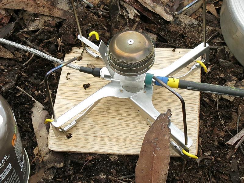
On the 20th of June I gave some details about making the hoses for the stoves. Having just spent a really exciting day making some more bits for hoses, I thought I would bore you with the details.

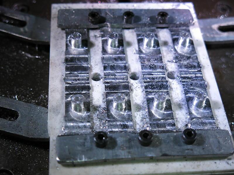
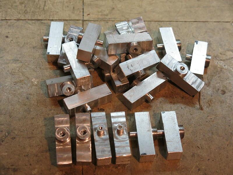
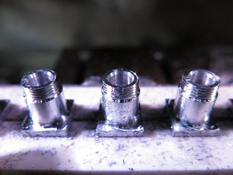
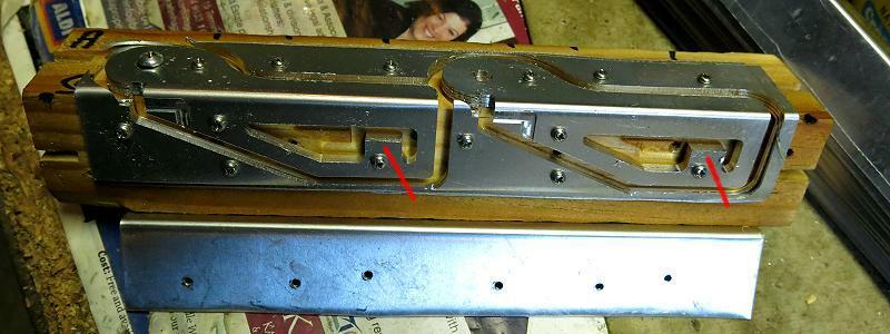
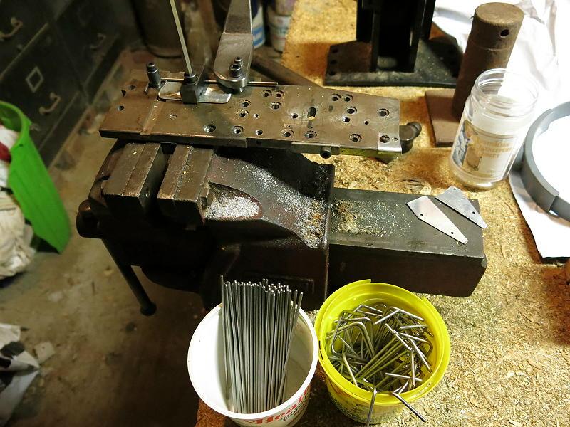
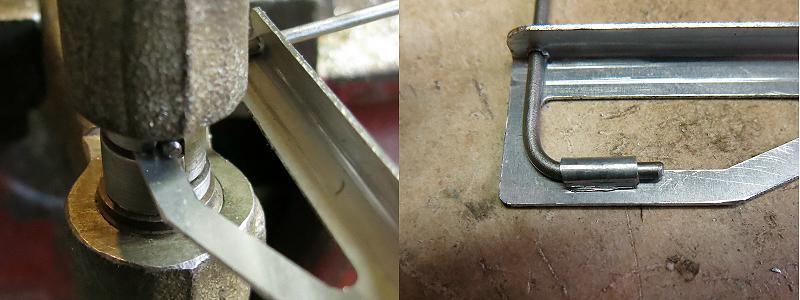
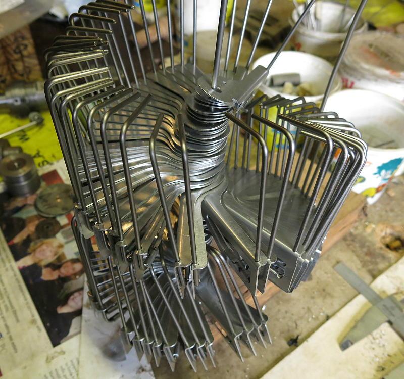
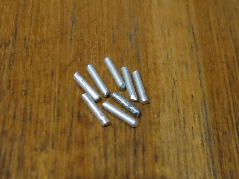
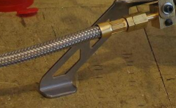
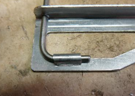
This photo shows the bits which get fitted to the end of each hose. The flat plates are the Retaining Plates, the round bits of tube are the crimp rings which clamp the braid to the end fittings, the two end fittings on the right are for the canister connector and for the stove connection. So far, so good. The collection of tiny tubes in the middle are the ‘Lock Tubes’ which go inside the hose, forcing it outwards against the holes in the fittings.
You see, you cannot get a length of hose up a tight hole in the end fitting: there has to be clearance. That clearance is a problem: even if there is only 10 microns of clearance between the hose and the fitting, that makes a leak area of about 1/3 of the jet size. Fuel would pour out there.
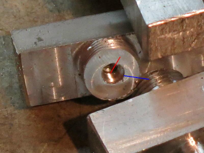
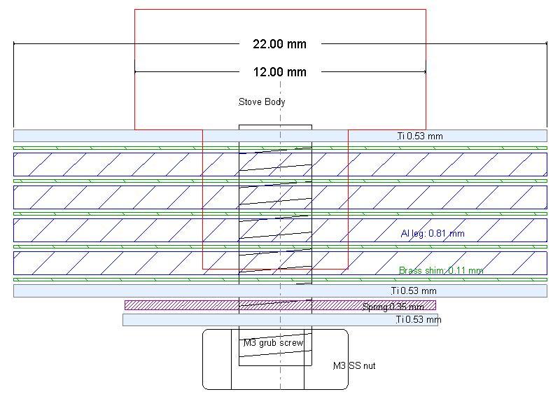
The hose is the grey part, the fitting is the green part, and you can see where the gas would leak out between the two. So a small ‘lock tube’ (red) is forced into the hose to expand it out and prevent any leaks. Ah, but I have to make this lock tube.
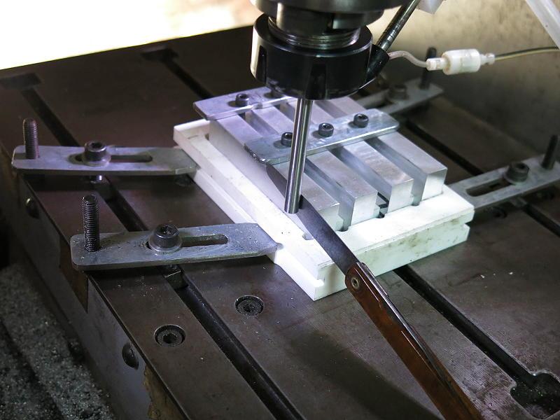
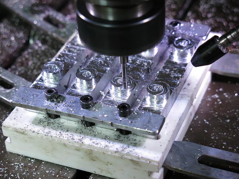
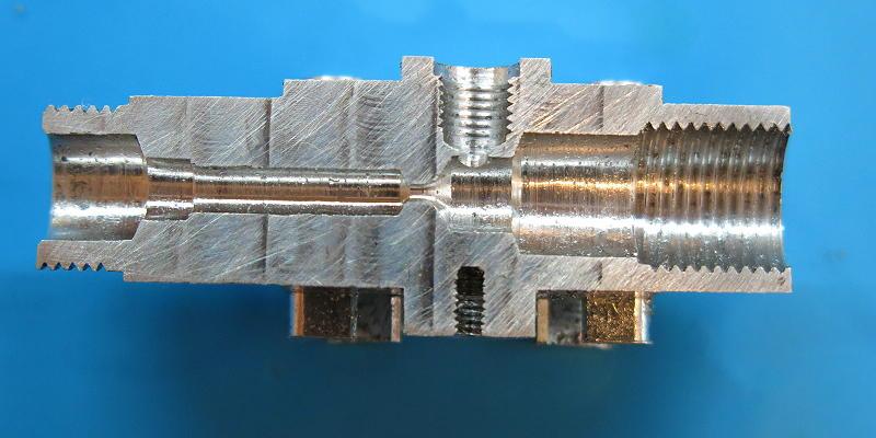
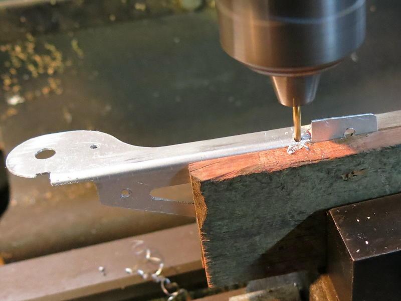
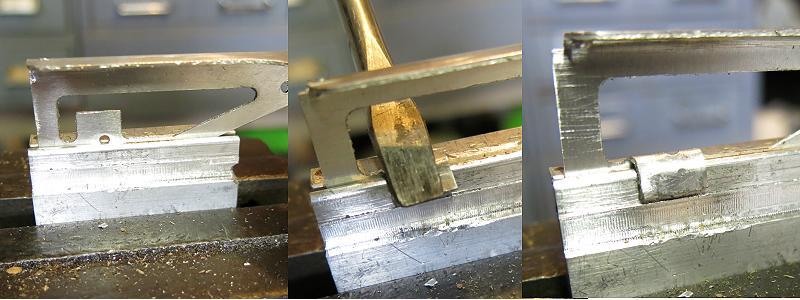
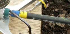
I start with some SS hypodermic tubing and cut off short lengths. That sounds simple. However, one end of the tube has to be tapered so it will push the hose outwards when it is inserted. This is done by careful design of the parting tool. You can see the tapers at the left hand end of each bit of tube.
Of course, if I just parted those bits off over a lathe bed covered in swarf, I would never find them. So I threaded a bit of 1 mm Ti wire through the hole and collected them as they came off.
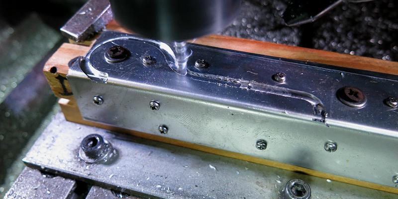
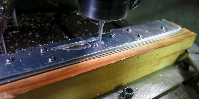
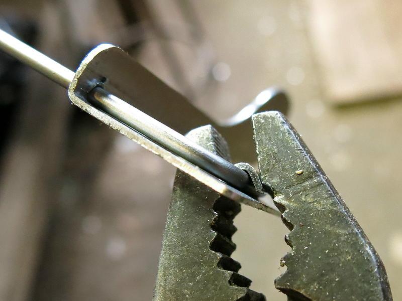
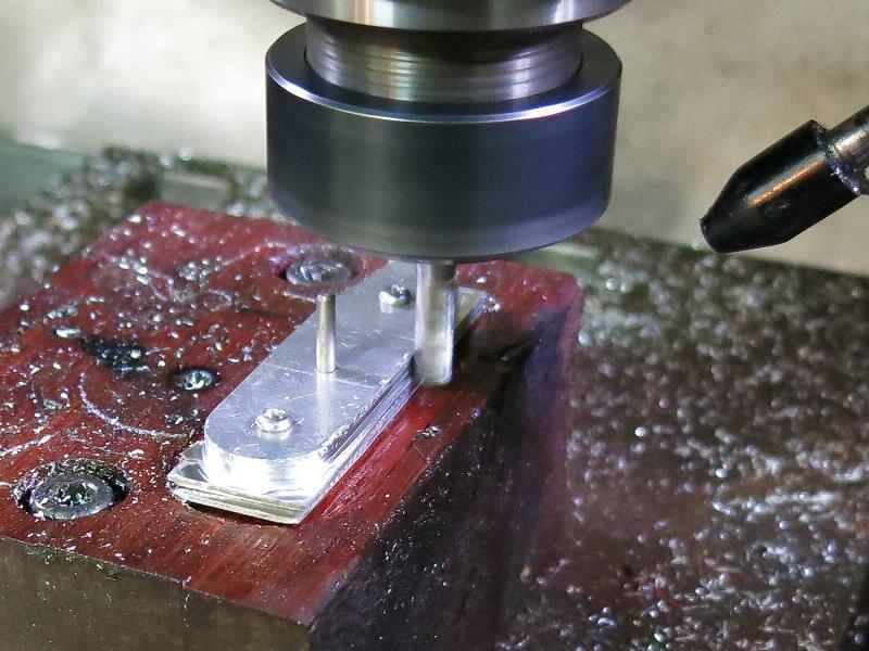
Even though the tip of the lathe tool was sharp, there was still a burr formed on the inside of each end of the bits. This had to be cleaned out before the tube could be forced into the hose. This was done, one bit at a time, with a 1.35 mm drill bit. I had to hold the tube itself with pliers while the drill bit was used.
There is another reason why I had to clean out the inside of the tube. Look at the diagram above of the hose and connector. It looks as though the lock tube (in red) can just slide into the hose, but that is not so. Despite the tapered end going in first, some of the PFA plastic is forced out ahead of the tube, a bit like dirt in front of a bulldozer. After all, the plastic is not very compressible. When I started I found that a blunt end on the hose could pile enough plastic at the inside end of the tube that the hose could be nearly blocked – so cleaning the plowed-up plastic out of the way was done with the same 1.35 mm drill bit.
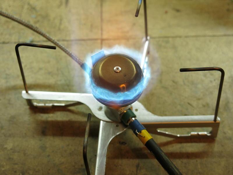
Provided all these little steps are done carefully, the hose passes both liquid fuel and gas very nicely, is solidly anchored into the end fittings, and does not leak gas. But doing it all manually is a shade tedious. Oh well.
I did try to get these lock tubes made by a small parts manufacturer. They declined. Smoothed ends they could do, but a tapered end they could not.