Topic

Engineering the V4 Winter Stove


Forum Posting

A Membership is required to post in the forums. Login or become a member to post in the member forums!

Home Forums Gear Forums Make Your Own Gear Engineering the V4 Winter Stove

Viewing 25 posts - 51 through 75 (of 77 total)
  • Author
    Posts
  • #3670174
    Roger Caffin
    BPL Member

    @rcaffin

    Locale: Wollemi & Kosciusko NPs, Europe

    We have melted snow in our 1.5 L Ti pot on a number of occasions. At medium power a canister stove will be pumping out above 2 kW, which seems plenty to me. Our kitchen kettle is 2.4 kW.

    The blue is heat shrink tubing. Why all the different colours there? I can’t remember. That was a development model, so who knows? Production uses just yellow heatshrink.

    The bit of the handle that goes into the CF tube is longish, about 15 mm long by 6.2 mm ID, and the fit is tightish. Yeah, all things are relative :) The CF tube was found to vary very slightly on ID as well. However, in practice the CF handle does not fall off the needle valve; in fact I usually need to give it a slight tug to get it off. No guarantee that every handle will fit exactly like that, but they don’t need to. Certainly, it does not need to be propped up!

    See photo 4 of June 23rd as well.

    Cheers

    #3670479
    Roger Caffin
    BPL Member

    @rcaffin

    Locale: Wollemi & Kosciusko NPs, Europe

    Canister Connector

    I have left this section to last because I did have some connector
    assemblies left over from the V3 production, which I was able to use to satisfy a second batch of orders. Here they are, stacked up in my office ready for posting.

    However, those canister connectors have now all been used up, I have more orders still, so I have to make some more. This part may go a bit more slowly, partly because it is so long since I made these parts. It takes time to work through the great pile of old programs to find out which ones are the right ones. Documentation! (Yes, it exists, but in multiple versions!)

    This is a simplified engineering cross section of the canister connector. The blue is the main body; the green is the Spider, the pink is the cam valve; the brown is the Main Ring, the yellow is the brass valve actuating pin; the grey rectangles in the middle with green edge form the pin retaining washer; the flat green with black edge things at the two ends are the retaining plates; the brown circles are O-rings, the hashed green at the left is the hose connector assembly, and the mass of lines at the top is a collage of cross-sections of the three different canisters. They do have different profiles, don’t they? Most annoying! And the zigzags are the main thread.

    This photo shows most (but not all) the parts of the canister connector. Missing are the the clear plastic pin-retaining washer which holds the brass valve pin in place and the big fat O-ring (7x3x13 mm) which seals the connector to the canister. The two retaining plates which hold the hose connector and cam valve in place are only shown in the top unit, where they are in place. Each of them is secured by 2 self tappers.

    Why only two self tappers when there are 4 holes in the plates and in the main body? Two are quite sufficient, but what happens if there is an accident (how???) and the holes in the plastic are damaged? Then the user can switch to the unused holes with new screws: no repair machining needed. The amount of programming needed for this is trivial, so why not include it? Murphy’s Law says that having the provision there means it will never be used …

    At the bottom left we have the ‘Spider’, which is the locking mechanism which secures the connector to the canister. It is threaded onto the main body, which is then capped by the Main Ring (bottom right). The red lines show the screws which hold this Main Ring in place. Again, there are 4 holes but only two are used. The same explanation applies, except that in this case the extra holes HAVE been used when the Spider was accidentally screwed right off the main body, ripping the original self tappers out and damaging the holes.

    In the middle bottom we have the brass valve actuating pin. Getting the right length for this was an extremely involved process: see the differing canister profiles at the top of the first drawing just above. I managed.

    One of the key elements in making this work is what we might call the ‘throw’ of the cam. If it is big enough you can handle any canister, although if the throw is too big you might not have much left of the control valve.

    By winding the Spider to the top of the thread (with very light fingers), the Main Ring (red line) is withdrawn from the fingers (green line) of the Spider so they can deflect inwards – as the whole thing is pushed into the Lindal valve. Then the main body is screwed in towards the canister so the Main Ring pushes against the inner shoulder (blue line) of the fingers and pokes them outwards, to lock under the rim.

    What happens if you accidentally unscrew the main body too far, ripping out the two self tappers? You end up with the Spider still in place in the Lindal valve, held there by the Main Ring, and the Lindal valve nipple is in the middle, blocking all your attempts to get the Spider out. This is tricky. I have seen one case where the Spider was levered out with a screwdriver, but that wrecked the Spider. Most unfortunate. (Acknowledgement to an unnamed customer.)

    This is another view of the connector. The colours are different here: sorry about that. The important bit is the brass valve actuation pin (blue line) at the right. This is pushed outwards by the white cam valve (also blue line), to open the plug valve in the Lindal valve assembly. When the Ti wire handle points away from the canister, the pin is withdrawn, the Lindal valve shuts, the gas flow ceases, and that Lindal valve is ultra-reliable. This is an on/off safety valve.

    Finally we have the black O-ring (brown line) which seals all this to the nipple on the canister. As some canisters have slight variations in dimensions (even within one style), that O-ring is fat so it can
    accommodate those variations. Getting the dimensions down inside there and the length of the brass pin right so the whole connector could handle any of the purposed canisters took a lot of measurement and experiment. (Purposed canisters: screw-thread, Campingaz and Powermax. I use all three.)

    Mind you, getting the hose connector (going into the left side of the main connector block in the previous photo) to a satisfactory state also took many experiments. Some of the rejected versions might have been OK, but in the end I went for the aluminium version shown at the left. It has been very reliable, and stays attached to the hose very well.

    #3671084
    Roger Caffin
    BPL Member

    @rcaffin

    Locale: Wollemi & Kosciusko NPs, Europe

    What can go wrong with O-rings and plastics

    I am going to digress slightly here to cover what was a bit of a puzzle at the time. It’s a detective story with an unexpected outcome. First, some background theory.

    An O-ring is a thin bit of (usually) rubber fitted between a mating shaft or piston and the bore it goes into, to seal the gap. For instance, if there is liquid propane on one side of the O-ring and a naked flame on the other side, you don’t want any leaks. This applies of course to stoves. Equally, if you are driving a large backhoe around with a ton of soil in the bucket, held up in the air by hydraulic cylinders, you don’t want any leaks there either. I should add that the pressure in hydraulic systems is usually more than 10x that in a gas canister, say 8,000 psi. O-rings matter.

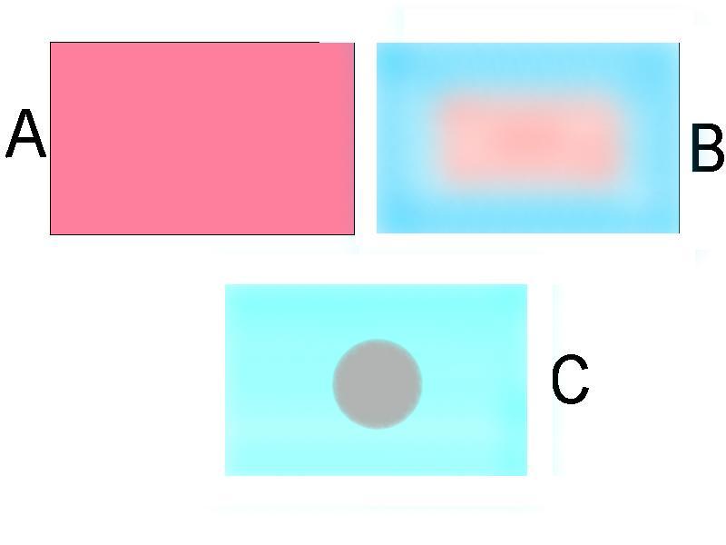
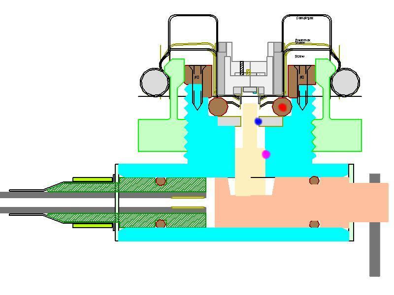
    The O-ring sits in a groove (usually in the piston) and presses against both the inside of the groove and the bore. We often draw the O-ring as in case A above, but reality is that the top and bottom of the O-rings are flattened against the bottom of the groove (green) and the hole or bore it is in (blue). Note that this only shows one side of the groove and bore: imagine a centre line at the bottom. The O-ring is usually also pushed hard against one side of the groove by the pressure and this improves the seal.

    How much initial compression to use on the O-ring is critical here. There are all sorts of formulae available for this, and I have not found any which are easy to use or of much use. Let’s just say that for the 1.5 mm thick O-rings I use, initial compression (by diameter) of 0.2 – 0.3 mm (15 – 20%) is appropriate. But this is very complex.

    Calculating what compression you need is arcane and obscure. O-ring manuals of 9 MByte size wax eloquent on every aspect of selection and design – except for this. Apparently, ‘it all depends’. You have to consider dimensional tolerances on the piston, the bore, the O-ring cross-section, the hardness of the O-ring, how much the O-ring is stretched in its groove, how much compression ‘set’ it has acquired … and more.

    So typically the groove in the cam valve in my stove is about 5.60 mm diameter, while the bore is 8.00 mm. This gives a difference of 2.40 mm by diameter, or 1.2 mm by radius, compared to the 1.5 mm cross-section. This is usually enough to provide a seal, even with tolerances. Of course, all surfaces must be smooth, but that comes with the manufacture.

    A problem is found

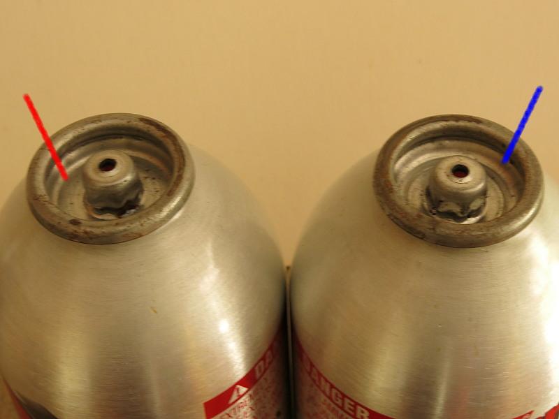
    So I was a bit surprised to find a canister connector leaking at the valve in a routine lab test. Then a customer reported the same problem, and more recently a second customer also found a leak. How? This is where we go forensic.

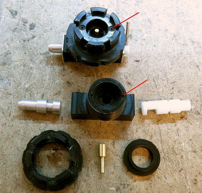
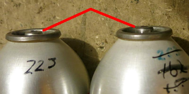
    I stripped down the leaking unit I had and began to check it carefully. To my amazement, I found that the main bore through the acetal connector, which had been carefully reamed out to 8.00 mm, +/- 0.05 mm or closer, was now about 8.15 mm. Now a drift of 0.05 mm would be a bit big, but 0.15 mm was incredible. Unfortunately it was real. How?

    To explain this we have to look into the manufacture of slabs of acetal. They are cast when hot (case A, ‘red hot’, >168 C), and allowed to cool down. (That simple sentence hides a LOT of complexity, but no matter.) While cooling the whole lot it will of course shrink a bit: everything does. Acetal has a coefficient of thermal expansion of about 9.7 x 10^-5 per C. Provided this cooling is done to spec, all is well. In special cases the slab can be warmed up and held at an elevated temperature for a while, so that everything relaxes and equalises. This can be called ‘tempering’.

    However, sometimes things get confused in the factory and material is shipped before it has been properly tempered. What you get then is a slab or a strip which has cooled on the outside to a stable state (case B, blue outer), but which did so while the inside was still hot and expanded (pink). Then the inside cools down while it is sitting on MY shelf, and you get internal tension. This is not stable.

    So I drill a hole through the middle and ream it to 8.00 mm diameter (dark spot in middle of case C). But the tension in the material is still there, and the material slowly relaxes, by pulling the insides towards the outside shell. The hole grows. The O-ring seal begins to fail as the ‘squeeze’ is lost. Aaarrrgghh is a suitable comment.

    A solution

    If the hole had shrunk I coud ream it out, but I cannot add material inside an oversized hole. Nor can I pad the bottom of the O-ring groove out and retain the seal – and yes, I did try. The ‘cure’ only lasted for a very short time.

    Ah, but if the 1.5 mm cross-section (CS) is no longer fat enough to seal, can I find a fatter O-ring? Well, not from any standard main-street supplier, but I found a company which not only made their own O-rings, but had dealt with this problem before. They carried O-rings just slightly larger than 5.0 ID x 1.5 CS for this very purpose: 5.1 mm ID x 1.6 mm CS.

    I bought some, tested them, and the problem was solved. I had a bit of a moan at the plastic supplier, who conceded my diagnosis and replaced the material with properly tempered stuff.

    Update Notice

    If you have one of my stoves and the main bore at the canister connector may be leaking, then two steps are needed. First, immerse the whole stove in water with the needle valve shut and the Lindal valve OPEN and see if there are any bubbles appearing at either end of the main bore. Then, if there are bubbles, contact me and I will send you replacement O-rings at no charge.


    #3672643
    Roger Caffin
    BPL Member

    @rcaffin

    Locale: Wollemi & Kosciusko NPs, Europe

    Machining the Parts

    The Spider

    I will abbreviate some of the details from here on. A single slab of plastic is clamped down on a sacrificial base plate (which can be chewed up and thrown out and replaced), many holes are drilled in the gaps where the spiders are not, and the slab is then screwed down using these holes. The design is such that the CNC can actually machine up to 3 rows of 6 units at a time, which is good because there are many tool changes.

    First the interior of each Spider is excavated. Then the outside of the fingers has the excess material removed down to what will be the knurled ring and inwards to the tip of the fingers (blue dot below). There is a lot of stuff (swarf) flying around at this stage.

    Then the inside is thread-milled (green dot) so it can screw onto the Main Block. A rather large (solid) cutter is used here. You could try tapping this later, but at 20 mm OD with a 1.5 mm pitch, you would be struggling to hold the Spider without breaking the (Spider) fingers. The torque required might not do your own fingers any good either.

    The inside of the fingers (red dot inside) has then to be recessed for flexibility. This requires a custom cutter shaped on my (MYOG) Diamond Tool & Cutter Grinder. I guess I could get one made somewhere, for a large price. Mine works. The outside of the fingers is undercut (red dot outside) as well so they can fit inside the Lindal Valve. The outside diameter of the thin bit of the fingers is set by the diameter of the rim on the Lindal Valve, and the shape and size of the undercut is set by the cross-section of the rim.

    Then 6 radial cuts per Spider (yellow dot) are made to create the flexible fingers. Without these cuts the whole thing would still be rigid. Owing to the machining characteristics of the UHMWPE I sometimes use, I have to remove small ‘feathers’ of material from the fingers at the end – with a very sharp new box cutter blades. Old or used blades need not apply. It is rather tedious work, although the material makes good Spiders.

    The alternative is to use nylon or more acetal. The acetal machines well, and seems to work OK provided the thread is cut with a tiny bit of looseness: maybe just 0.1 mm extra radius. It helps if the surface of the thread is slightly lubricated, to passivate the dangling molecular bonds the machining has left. Silicone grease and graphite grease both work – in small quantities so they don’t go everywhere!

    After this the base flange has to be machined. A circle of holes is drilled around the rim to make the knurling. Without this for a grip, working in the cold and wet would be difficult. The photo used here is an old one of a Spider with square recesses (pink dot) in the rim; the current design has far more elegant round recesses.

    At this stage all the Spiders are still joined together at the bottom. But you can’t just mill the Spiders out: they would go everywhere once the plastic is removed and be destroyed. Instead, each spider is clamped down with a little shaped clamp (the white bit in the middle in the first photo above) and then the edge is machined away. Only then can I unscrew each clamp in turn and extract the Spiders. (Footnote: the plastic is actually black, which is difficult to photograph.)


    #3672746
    DAN-Y/FANCEE FEEST
    Spectator

    @zelph2

    The threads identified by the green dot screw onto the “main block”

    So the only thing that holds the valve to the canister is the tension of the “fingers” aginst the rim of the canister?

    #3672748
    Jerry Adams
    BPL Member

    @retiredjerry

    Locale: Oregon and Washington

    My Exponent F1 stove had this annoying property that the O ring would seal fine at operating temperature, but if I left it screwed onto the canister overnight and it got cold, like 32 F, things would shrink and the O ring starts leaking.  In the morning the canister is empty.

    #3672754
    Roger Caffin
    BPL Member

    @rcaffin

    Locale: Wollemi & Kosciusko NPs, Europe

    @Dan

    So the only thing that holds the valve to the canister is the tension of the “fingers” aginst the rim of the canister?
    Absolutely NOT! I do not rely on the strength of the fingers in bending against the rim at all.

    Go back to my posting of August 12th and look at the several diagrams and photos there. The Main Ring, which is part of the main connector body, holds or even forces the lugs on the fingers outwards under the rim. There is a really positive lock between the connector and the canister that way.

    As for the strength of the fingers in lengthwise tension, let’s just say it is ‘adequate’ for the task. Plastic can be very strong in tension. I did look at the figures for the strength of the materials but quickly decided that something else would fail first.


    @Jerry

    Yeah, I would never suggest leaving a stove screwed on overnight. IF the O-ring was Viton and the stove was screwed on firmly it should have survived the treatment, but if the O-ring was a cheaper material – who knows?
    The problem with screwing the stove on tightly every time is that the engineering disaster that is the ‘thread’ will soon strip the much softer brass thread out of the stove. Been there, had that happen.

    Cheers

    #3672813
    DAN-Y/FANCEE FEEST
    Spectator

    @zelph2

    Absolutely NOT


    No question about it….I was wrong, absolutely!

    I did as you said, went back and read the post. “Main Ring pushes against the inner shoulder (blue line) of the fingers and pokes them outwards, to lock under the rim.”

    Now I got it! Absolutely!

    That feature reminds me of the Campingaz connection design.


    #3672816
    Roger Caffin
    BPL Member

    @rcaffin

    Locale: Wollemi & Kosciusko NPs, Europe

    That feature reminds me of the Campingaz connection design.
    Couldn’t possibly be … :)
    It is a MUCH more reliable connection, far better than the EpiGas idea.
    Cheers

    #3672824
    DAN-Y/FANCEE FEEST
    Spectator

    @zelph2

    I knew you’ld say that….

    Yours is more of a push onto the canister and turn/twist to activate the fingers against/under the rim. Like the Power Max…only much better.

    #3672841
    DAN-Y/FANCEE FEEST
    Spectator

    @zelph2

    A little research and I found the information on how to use your canister connector. Now I’m in a better place ;)

    Cheers


    To attach the connector to a canister you first ‘unscrew’ the solid core from the spider a short distance, until the solid tip is clear of the lumpy lugs. This lets the fingers compress inwards a bit. Then you insert the fingers part (the ‘spider’) into the Lindal valve: the lugs ‘pop’ in past/under the rim. If they don’t pop in easily, the core (or the spider) needs to be unscrewed a little more: force is not needed. To anchor the connector to the canister once it has been inserted, you do up the core by screwing it in. This first locks the lugs in place as the smooth top end of the threaded bit slides between the fingers in the lug region (see previous photo).

    With a bit more screwing the O-ring comes into contact with the spigot on the Lindal valve. You continue to do the core up till the fit feels firm. Not too much force is needed, and it easy to tell when the O-ring is compressed. When the fit feels secure and the stove has been placed upright in place on the ground, then (and only then) you turn the Ti wire handle of the cam to drive the brass pin into the valve and let gas flow. At this stage you can have the needle valve on the stove shut or open – if the latter you quickly light the gas.


    #3672862
    Roger Caffin
    BPL Member

    @rcaffin

    Locale: Wollemi & Kosciusko NPs, Europe

    Like the Power Max…only much better.
    I could have copied the PowerMax (Xtreme) fitting, but it has defects. The tale is worth telling, and it comes in TWO parts.

    To operate the Powermax connection you have to FIRMLY push the PowerMax canister into the connector you have shown. (Um – my photo I gather?) Then you turn the canister so the cams open the fingers under the rim.

    The first problem was that sometimes the spigot or nipple of the PowerMax canister stuck above the rim at different heights, depending on the canister batch. (See canister on the right.)

    If it stuck up too much the lugs on the connector could not reach the rim. But other types of canister (screw-thread, Campingaz) had the top of the spigot approx level with the rim, and that is how Lindal tech drawings showed it too.

    I (CAUTIOUSLY) depressed the spigot until it was flush with the rim, and the connection worked.

    I informed Coleman of the problem – with a photo. They took the photo seriously and checked. Ooopps! The canister crimping machine was found to be badly out of adjustment. It was deforming the bottom surface of the Lindal valve. Compare the flat bottom with the red line on the left to the distorted bottom with the blue line on the right. This lack of adjustment was fixed, and better canisters flowed forth.

    So far, so good, but what if you still cannot get the canister far enough into the connector? Then it is a cold dinner. Some PowerMax Xtreme owners had this problem in the field, even with ‘good’ canisters, although once they got home the problem vanished. They complained to Coleman (the makers), but the Coleman tech staff could not duplicate the problem. This I had from the Coleman tech staff, who were now willing to chat after the previous incident.

    I too had the problem on one cold ski trip, one night. But the previous night the stove was OK. Yes, the connection had been difficult to make, but it had been possible. So I probed, and pondered.

    An idea came to me, I acted upon my idea, and the connection was made. So, what had I done? All I did was to warm the little O-ring (green line) up. The Viton rubber softened, the O-ring squashed flat, and the connection worked. But if the O-ring was cold it was too stiff and would not compress.

    Could not the Coleman staff have discovered this? Well, no: their testing was all done in an air-conditioned lab! The O-ring was always warm.

    Coleman modified the connector. They deepened the recess behind the O-ring and added a second O-ring on top of the first one. To be sure, the O-ring could still get cold, but each O-ring now had only to compress have as far. This too worked. Sadly, I cannot find a photo of the modification.

    It seemed to me that the PowerMax connector and canister had to be ‘just right’ to work. But we know from experience that canisters do vary. So I wanted an adjustable connection which could accommodate such variation: hence the screw thread in the spider. As you quoted: You continue to do the core up till the fit feels firm. Not too much force is needed, and it easy to tell when the O-ring is compressed. The design allows for considerable variation in the canister or spigot – which does in practice happen.

    Cheers

    #3672949
    DAN-Y/FANCEE FEEST
    Spectator

    @zelph2

    You continue to do the core up till the fit feels firm. Not too much force is needed, and it easy to tell when the O-ring is compressed. 

    In frigid winter temps how does one do that with gloves on or even with gloves off for a min. or two?  We all know you use yours in the confines of your tent ;)

    #3672985
    Roger Caffin
    BPL Member

    @rcaffin

    Locale: Wollemi & Kosciusko NPs, Europe

    In frigid winter temps how does one do that with gloves on or even with gloves off for a min. or two?
    All I can say is that I have never had a problem with that. I can really feel when the core hits the O-ring: no problem at all. I generally have a good jacket on so I can take my gloves off when cooking. Once the stove is going, there is plenty of warmth above the stove.

    It is a bit different with an upright stove. When screwing one of those onto a canister you are simultaneously depressing the Lindal valve inside the canister via the pin in the bottom of the stove, so there is a lot more gradual force. This can mask the feeling of the O-ring. With my canister connector there is only the O-ring to depress when you are attaching the connector. You screw the core in lightly until suddenly you hit the O-ring. Actuating the Lindal valve comes later in a separate action.

    Yes, I cook dinner inside the tent, but in fine weather we have morning coffee out in the snow.

    What’s not to like?

    Cheers

    #3673150
    DAN-Y/FANCEE FEEST
    Spectator

    @zelph2

    What’s not to like?

    I don’t like leaky canister valves ;)

    Hey, what stove is that you are using in the photo….looks heavy?  I see you like that refillable Power Max canister.

    #3673208
    Roger Caffin
    BPL Member

    @rcaffin

    Locale: Wollemi & Kosciusko NPs, Europe

    It’s a Coleman Xtreme stove, from about 2005, which is long before I started making my own stoves. And from when the PowerMax canisters were still available – sigh. Good stove, just a bit heavy, and restricted to PowerMax canisters unless you have a (heavy) Coleman screw thread to Xtreme adapter. They are a bit rare.

    It was the first ‘morning tea in the snow’ photo I cam across in a quick scan. I thought one was enough.

    I have never had a canister valve leak, but I keep the plastic cap on the canister at all times when it is not in use. That keeps the dirt out.

    If you have a canister valve which you suspect is leaking, invert the canister and give the valve a very fast brief poke with something like a CLEAN Ti wire stake. OUTSIDE! The flow of liquid fuel should flush any dirt out and let the valve seal properly.

    Cheers

    #3673211
    Jerry Adams
    BPL Member

    @retiredjerry

    Locale: Oregon and Washington

    I’ve had one canister leak.  Out of many many.  So rare as to not worry about?

    After I used it the first time and unscrewed stove, it started leaking, so I left stove screwed on.

    I tried shaking and poking.  I put in freezer so it wouldn’t leak, then tried poking some more to no avail.  So I just left the stove on it and used it until empty.

    #3673254
    DAN-Y/FANCEE FEEST
    Spectator

    @zelph2

    Your review of the stove back in 2007 was a good read. In the review you said you had field tested the stove for 5 years.

    Our normal practice in reviewing a piece of gear is to first use it in the field for while. We did the same with the Coleman Xtreme, except that I have been using one of these stoves in the snow for about six years.

    Wow, a 11.0 oz (312 g) stove was not an issue back then for winter use, good to know.

    Another interesting note relating to design:

    Setting this stove up requires just two actions. First, I open the three legs out into the tripod arrangement. That takes a few seconds. Then I connect the valve to the tank, which requires that I push the two together and then twist the tank a quarter turn. This normally takes me about ten seconds, although I am aware that a few people have reported problems making this connection in very cold weather. When I enquired about this I was told that Coleman was aware of the reports, but their staff had not been able to reproduce the problem. Anyhow, if the connection is not made correctly, you just don’t get any gas out, which is safe. If this happens, undo the connection and try again. I have not had this problem myself once I realised that I need to press the valve and canister together with a little bit of force in the cold.

    Here ya go, morning coffee outside:


    #3673266
    Roger Caffin
    BPL Member

    @rcaffin

    Locale: Wollemi & Kosciusko NPs, Europe

    Hi Dan

    Yeah, that was a good trip. ‘Enough’ snow for skiing, but with sunshine and the occasional grassy patch for sitting on. Morning coffee – plus biscuits with jam and honey.

    In those conditions we often prefer to camp ON the snow. I can get a really flat site on snow, but the snow grass can be a bit bumpy at times. Just need a good airmat.

    My comments about the problems connecting the PowerMax canister were made before I managed to sort them out with Coleman. You will notice that I wrote their staff had not been able to reproduce the problem: that was because they were doing the testing in a nice warm lab, when the O-rings were soft.

    Cheers

    #3674102
    Roger Caffin
    BPL Member

    @rcaffin

    Locale: Wollemi & Kosciusko NPs, Europe

    Material Selection

    How boring you might think – but in fact the range of materials used to make this stove is huge. Finding out which material was suitable (and which was not) was a bit like a detective story.

    The stove itself has at least 4 different aluminium alloys: 2011 for
    the needle valve and the burner column, 6061 for the stove body, 5038 for the pivoting legs and 5005 for the heat shunt.

    The hose has PFA for the tubing, stainless steel for the braid (type
    unknown), 2011 aluminium for the end fittings, although the crimp
    rings are softer 5005, and a very hard stainless steel for the lock
    tubes which go inside the PFA hose at the ends.

    The burner head has a 5038 base on top of the 2011 tube, a 3Al-2.5V
    titanium tube ring around the outside, 308 stainless mesh, CP titanium (ie commercially pure) for the top cap, and stainless steel (probably 308) for the inner caps.

    The pot supports (attached to the 5038 pivoting legs) are 6Al-4V
    titanium alloy – one of the best and most common ones.

    Yes, I have shown this photo of the canister connector before, but it
    does show the bit to be made. The Main Body is acetal, a semi-
    crystaline plastic which machines well and is fairly rigid. The acetal
    bar is mostly OK, although as noted above I did get one batch which had not been properly tempered.

    For a while I thought that the Spider (green) could not be acetal as
    threading acetal into acetal (in the style of a nut and bolt) seemed to jam. It seemed that the two freshly cut acetal surfaces ‘grabbed’ each other: cut off molecular bonds waving in the breeze were reattaching. So for a while I went with UHMWPE: it has suitable strength and flexibility and is fully compatible with the acetal. However, it machines poorly, leaving lots of ‘feathers’ at the edges. These have to be cleaned up by hand – think a very sharp blade and lots and lots of patience. By adjusting the clearances on the thread I found that I could also use acetal for the spider. I am sure the Nylon 6 or 6.6 would also be suitable.

    The Cam Valve (pink) has the brass pin (yellow) sliding on it, so it
    needs to be both stiff and wear-resistant. It could be nylon 6 or the
    more expensive PETP (also used in Coke bottles etc). It can’t be any
    sort of fibre-reinforced material (glass and carbon fibre versions are
    available) as the cut ends of the fibres will abrade the bottom end of
    the brass pin. Care has to be taken with the machining as flex in the
    stock is very possible, and that queers the dimensions if allowance is
    not made. Nylon 6 (black) flexes a little bit more than PETP, but the
    flex is within the range of being corrected for. I tried some Nylon 6.6 (in natural) which I had in stock as well, but it flexed like an
    uncooked sausage. It should not have been that weak, so I don’t know
    what was wrong there. I did not pursue the matter.

    The brass Actuating Pin (yellow) is hard machining brass (C385 I think) as opposed to soft bendable brass. Yes, there are quite a few different sorts of brass available, just like steel and aluminium. The 4.50 mm diameter Pin slides in a 4.70 mm clearance hole in the acetal Main Body. There has to be clearance for two reasons: first so the pin can slide up and down, and more importantly so the fuel can come down the hole to reach the hose. You might think that with 0.1 mm clearance at the side (purple dot) there is not enough room for the fuel, but it’s a long way around that 4.5 mm and the cross-section of the gap is quite enough.

    The Retaining Washer (grey, green border) which holds the brass Pin in place could be any of several materials as it is not critical. I use
    Lexan, mainly because I had it in stock and it does not break. While it helps if it jams in place, that is not critical. The fat Viton or
    Nitrile 7×3 mm O-ring (red dot) seals at the sides against the main
    body and simultaneously holds the washer in place. The hole in the
    washer (blue dot) has to have clearance so the fuel can go through.

    The Retaining Plates at the ends of the main body are 5083 sheet
    aluminium: an alloy which is stronger than the normal 5005 more readily available. While quite thin (0.83 mm), the part is only 12 mm square and the forces on it are not that large. It has never given any
    problem.

    Now if all you want is an alky stove, a simple Coke can will suffice.


    #3675509
    Roger Caffin
    BPL Member

    @rcaffin

    Locale: Wollemi & Kosciusko NPs, Europe

    I had no idea, when I started this blog, just how much work was involved in keeping it going! Oh well, another installment.

    Oooppss!

    This is just for light entertainment. I write my own CNC programs, rather than try to use a CAM system which takes a 3D CAD model and tried to generate the necessary CNC code. One of the reasons for doing it my way is that I take some pride in being able to do so, but another reason is that I doubt that the low-end CAM programs I could afford would be able to handle the designs. Well, maybe one of them could, but the result would run incredibly slowly and handle only one unit at a time, and it would need a 5-axis machine which I do not have. Not good enough. There are high-end CAM programs which might cope, but they cost over $50,000 and usually assume a 5-axis machine anyhow.

    So I start off with a program which sort of works and then try to optimise it, or ‘improve’ it. It is a rule in the home CNC world (and also in the industrial CNC world!), that you need to test the program ‘in the air’ before cutting material. That means running the machine without a cutter and with the spindle up in the air – hence ‘cutting air’. You watch closely.

    Well, I made a tiny tweak to the program for the Spiders and was confident it looked OK, so I ran it without testing.

    (This photo should be horizontal, not vertical. I have no idea what the BPL SW is doing at this stage.)

    The lower Spider is obviously wrong! Obviously, I should done the air cut stage first. I got the Z axis height wrong and the cutter went straight through the whole side of the Spider in one hit. All very stupid of me, but it could have been worse. With plastic one can get away with such bungles (occasionally); if I had been machining steel or even good aluminium the cutter would have snapped off immediately.

    In the event it did not matter. This Spider was the first in the whole array, so it was by way of being the test unit. I had already made another mistake, this time in loading the cutter, and taken off about 2 mm more from the top of the fingers than was intended. If you look closely at the tops of the fingers on the damaged unit you can see the difference from the good unit on the left (the bevel on the top edge is missing).

    #3675793
    Roger Caffin
    BPL Member

    @rcaffin

    Locale: Wollemi & Kosciusko NPs, Europe

    The Cam Valve

    Fairly obviously these are machined on the CNC lathe, and one at a time, like the brass Actuating Pins. However, that does not make the offset cam section itself. After the basic body has been made, the unit is mounted in a round clamp with an offset ‘centre’ hole. This goes back into the lathe chuck and the offset cam section is machined. Then the unit is stuck into another jig at the right orientation and the hole for the Ti wire handle is drilled manually. The Ti wire handle is a press fit using the same jig.

    The crude notch at the top in the photo is not needed. It was an experiment to see whether the liquid fuel could get past the end of the cam – it can. Remember: the liquid fuel expands about 250:1, so a high flow of liquid is not needed when the canister is inverted. If the gas flow is slightly limited when the canister is upright, that is fine.

    This all sounds terribly simple, doesn’t it? But actually designing the cam valve and the brass Actuating Pin, or getting all their dimensions just right, was one of the hardest parts of the whole exercise. The cam valve is shown here in green and the pin is in orance. The ‘mess’ at the top is a composite of the three target canister styles” screw-thread, Campingaz and PowerMax. As you can see, they do NOT all have the same dimensions on their Lindal valves, and yet I want to use the same set-up with all three, without modification. How much ‘throw’ should the cam create? And how long should the Pin be?

    Brass Actuating Pin

    These are machined from hard brass rod. Ideally, this would be done with a bar feeder machine, but lacking that they are made one at a time. A bar feeder is very cute: the chuck opens (pnuematics), the rod is advanced a controlled distance, the chuck is closed, the machining is done, then the chuck opens and the whole process repeats. Great if you need 10,000 of the same thing.

    Instead I position the tool in front of the rod at the end of the last cycle, so I can manually advance the rod to the tool for the next cycle. Boring, but effective. Just don’t leave the thin rod stickig out any excess distance, or it will flex and the dimensions will be wrong.

    Ah, but what dimensions? As I said above, that is the question. If you look at the drawing above you can see the Pin in two positions: up, or opening the Lindal valve, and down or with the Lindal valve shut safely. The design of the cam controls the movement of the Pin up and down, but this does not decide how long the thin tip should be. The devil of it is that the distance from the surface of the spigot to the ‘face’ of the plug which is the heart of the Lindal valve differs between styles of canisters!

    I had to do some careful measurements of this recess into the centre of the Lindal valve using as many different canisters as I could find. The screw thread versions were ‘mostly’ all the same, give or take half to one millimetre, but the Campingaz and the PowerMax were different. The Campingaz recess was at least 0.8 mm deeper, while the PowerMax recess was about 1.1 mm deeper. Why? I do not know.

    To me, that meant I had to have a cam throw of at least 2 mm, preferably 2.5 mm. Now the throw is determined as shown here:

    This shows how the cam section of the valve moves as the valve is rotated. The movement of the Pin might be better shown thus:

    The blue line was for a slightly different arrangement, which in the end proved little different in performance. Focus instead on the red line. The grey line across the middle shows the 90 degree rotation position. I decided that I did not want the pin driving the Lindal valve open much before this amount of rotation, although one could easily go for something like 45 degrees. Anyhow, these dimension gave me at least 1.5 mm travel, which is comfortably more than the worst case I had found. The ‘free’ first 90 degrees of rotation allows for some error in manufacture (of the canister of course) – or for some user misuse.

    I should point out here that these dimensions depend on the O-ring used: it has a cross-section of 3.0 mm. If one reduced this cross-section to 2.5 mm, the effect would be to poke the Pin further into the valve. Thus one has an option here for an extra 0.5 mm travel if needed. So far I have not found any case where it was needed. But I do have some of the O-rings.

    This does assume of course that the plug in the Lindal valve which is pushed in by the Pin can actually travel that 1.5 mm. This is an uncrimped sample and an enhanced tech drawing from Lindal (also uncrimped):

    Given that the diameter of the spigot is a bit over 10 mm, it is clear that the spring E pushing the plug D against the seal C has a sufficient length to handle this. Since the spring has to accommodate a rather large range of pins (thick blue line) on commercial stoves anyhow (they do vary!), this is not unreasonable.

    So a quick recourse to the engineering cross section above gives me the pin length dimensions. The diameters are determined by the hole in the main connector block – or was the hole size determined by the pin diameter? It does not matter. What does matter is that the lower body of the pin is larger than the hole in the retaining washer, while the pin extension is smaller than the entry to the Lindal valve. That part was easy.

    #3676836
    Roger Caffin
    BPL Member

    @rcaffin

    Locale: Wollemi & Kosciusko NPs, Europe

    The Main Block

    If you look at the Main Block in one of the earlier photos, it is evident that it has to be machined from several directions. That is complex. At the same time, I want to be able to machine these parts in volume – say 6 or 12 at a time. What that means is some clever and precise jig making is required. Over the years I have spent a lot of time making jigs: as much time as making stoves. The other parts also need some jigs, but not as many. The bit about a jig however is that once you have made it, future parts made with that jig will be (near as damnit) identical. The parts become interchangeable. (Some people spend most of their time on a CNC making tools to make more tools: me, I make jigs or fixtures.)

    The first step is to machine the raw material (bars of acetal) to be used to exact size and all the same. Having the blanks to exact size means I can rely on their dimensions when several blanks are stacked together to speed up production. This is done manually, but all stacked together.

    Then some precise mounting holes are drilled into each bar – using the CNC for precision. This lets me stack several blanks together for mass production. The blanks are then mounted onto one of my (many) custom jigs (two drilled mounting brackets), and we can start.

    First, the main 8.00 mm bore through the Main Body is drilled. Since the material is plastic, an 8.00 mm drill bit always produces an under-sized hole (and an 8.10 mm bit gives an over-sized hole). So the 8 mm hole is later reamed to 8.00 mm diameter. As the reamer I use has a long taper at the end, this has to be done in the manual mill, with me hand-holding the blank. This is probably more reliable than trying to mount the blank high up in the air so the reamer can go through it. The reamer tends to self-align in the hole while I hold the part.

    In the same process as the hole is drilled, the edge is chamfered. This chamfer is to let the O-rings on the Hose Connector and the Cam Valve slide into the hole without having bits of rubber sheared off by a sharp edge. Plastic may be ‘soft’ compared to steel, but it is harder than the O-ring rubber. A damaged O-ring leaks fuel.

    Also some tiny (1.3 mm) holes are drilled on the end face for the self tappers which will eventually hold the Retaining Plates in place. This (and the chamfer) have to be done at both ends, which is easily possible as the 5 mm rods provide precise location. Jigs!

    To machine the threaded part which holds the spider, the part has to be rotated 90 degrees and mounted a different way. This is done using 8.00 mm rods through the bore that was just drilled and the same mounting brackets (but different holes of course). At this stage the blanks are still stacked together in bulk.

    A whole series of operations are needed to make the threaded section. The middle hole has to be bored out to several different diameters, and a hole drilled right through into the 8 mm bore for the brass Pin. This operation requires some manual intervention at each unit: I have to remove and replace the 8.0 mm steel rod through each of the bores as I don’t want to drill holes into them. The machine prompts and waits for each one. Then the outside is machined down to the diameter of the thread (20 mm) and the big M20 x 1.0 thread is thread-milled. I use thread milling here as it is much easier than trying to manually drive such a large die down the column, all the while keeping is square. Hey, the machine whirrs along while I sit back and watch.

    But wait: there is more! At this point in the process (ie before it has finished) the machine stops and I fit a Main Ring onto each unit. They are made to be tight fits. With them all firmly snapped into place, four tiny holes are drilled for the self tappers which will hold the Main Ring in place. See previous photo for a close-up. This drilling would be extremely difficult to get right if the two parts were drilled separately as the holes actually go down the face between the two parts – but done together it is simple. The holes are even countersunk to recess the heads.

    The operation is actually a bit delicate: I have to manually retain the Main Ring in position while the holes are being drilled rather close to my fingers. But I know exactly where the drill bit is going each time. Fast moving fingers.

    And yet more: the final stage sees the whole lot, still in one bar, inverted on the 8 mm rods, a shaped support block placed under the bar around the screwed section as it is remounted, and the units are milled apart. The support block is needed to prevent the units from rotating around the 8 mm rod as they are cut out. Well, it works fine in practice.

    Main Ring

    This is rather flat and is machined from a 20 mm rod. Fortunately the CNC can make 5 of these at a time: drill a deep hole for 5 units, machine one ring and part it off, then advance a short way and repeat … This works here because the source rod is so stiff; it does not work with the thin brass rod. Note the comments above about drilling the holes for the self tappers.

    Clear Washers and Retaining Plates

    These start out as flat sheets of material held down by clamps at the sides while the holes are drilled. They are then cut out between the holes. I usually mark the cut lines with dimples while the main holes are being drilled. The round washers are stacked up, clamped and turned down to size. The square Retaining Plates are just cut out.

    And when I put it all together, I have a complete stove. It just has to be cleaned and burn tested before it can be sold. At the time of writing this, I have a few left on the bench.

    And that brings me to the end! Thank you for reading.

    #3676869
    Jan Rezac
    BPL Member

    @zkoumal

    Locale: Prague, CZ

    Roger, thanks for documenting the design and manufacture of the stove in so much detail. It was a great read.

    #3676888
    Roger Caffin
    BPL Member

    @rcaffin

    Locale: Wollemi & Kosciusko NPs, Europe

    Hi Jan
    It was fun for me too.
    Cheers

Viewing 25 posts - 51 through 75 (of 77 total)
  • You must be logged in to reply to this topic.
Forum Posting

A Membership is required to post in the forums. Login or become a member to post in the member forums!

Get the Newsletter

Get our free Handbook and Receive our weekly newsletter to see what's new at Backpacking Light!

Gear Research & Discovery Tools


Loading...