
Introduction
Increasingly dirty fuel canisters are clogging the inverted remote canister stoves I’ve been building. There are two solutions: prevention and filters. This article will cover both.
Background
I like lightweight remote inverted canister stoves, especially for winter use. When I started making and using them around 2008, I did not have too much trouble with jet blockages due to dirt from within the canister. By 2010 I was even happily selling my stoves. I did avoid any canisters labeled “Made in China” because the ones I tried were disasters.
Now roll forwards to 2022, and I find some of my customers have problems with the fuel flow and dirt. Their stoves are sometimes not working properly. It seems they are finding the dirt inside the stove, from the hose inlet to the jet. The dirt is there despite my attempts at cleaning the parts during assembly by:
- first using compressed air to blow all parts clean after machining,
- then immersing the parts in hot soapy water in an ultrasonic bath for 3 minutes,
- then flushing all the parts with hot water,
- then flushing the assembled stove (minus jet) with liquid fuel,
- finally doing a full test-burn on the bench, cycling the power up and down.
History
I will assume some familiarity with remote inverted canister stoves and my stoves in particular. Otherwise, some of this won’t make much sense. You won’t need deep technical knowledge, though, and I have lots of diagrams.
From Our Archives: catch up on Roger Caffin’s recent work on remote inverted canister stoves with this series of articles:
- Remote Inverted Canister Winter Stove V6.
- Remote Inverted Canister Stove V4, Part 1 and Part 2.
- DIY Backpacking Stove An Ultralight Vortex Burner for Winter Backpacking Part 1, Part 2, Part 3, Part 4, and Part 5
- Is a Heat Exchanger Pot Worth the Weight?
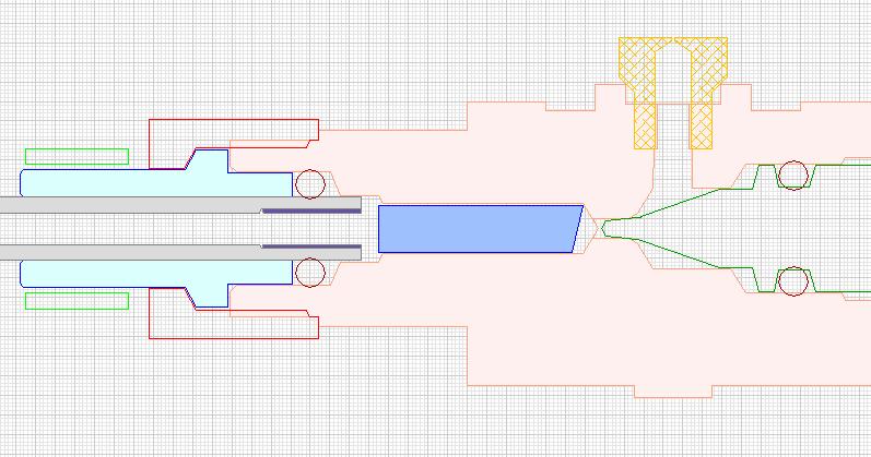
This diagram is a cross-section of the body of one of my stoves: it’s the big pink thing. There are variations, but this is typical. The hose connector is at the left (blue and grey), the needle valve (green) and the jet (yellow) are at the right, and the blue thing in the middle is the heat exchanger. Fuel flows out of the grey hose and down the thin space (0.1 mm) between the blue rod and the bore in the main body. There it absorbs enough heat that it vaporizes as it goes. Note that the fuel must be vaporized before it can burn and that n-butane boils at 32 °F (0 °C).
Way back around 2010, I was developing the concept for this heat exchanger to replace the traditional fuel pipe over the burner initially designed and used for petrol and kerosene stoves. I thought it was clumsy and unnecessary here. After all, a lot of heat is needed to vaporize petrol and even more so for kerosene (boiling point > 392 °F / 200 °C). But nowhere near as much heat is required to vaporize butane (boiling point 32 °F / 0 °C) and propane (boiling point -44 °F / -42 °C). Actually, with an upright canister stove, the fuel vaporizes inside the canister.
One early idea I had involved a Teflon rod with a spiral groove cut around it, inserted roughly where the blue rod above goes, at the input to the stove body. The idea was that the liquid fuel would have a long path in that spiral in contact with warm metal (the stove body), and it could vaporize as it went. It was not easy to make this bit as the Teflon rod is very soft and bendy, but I managed. I put the Teflon rod into an experimental stove, attached a canister, and fired it up with the canister inverted. My test rig looked something like this:
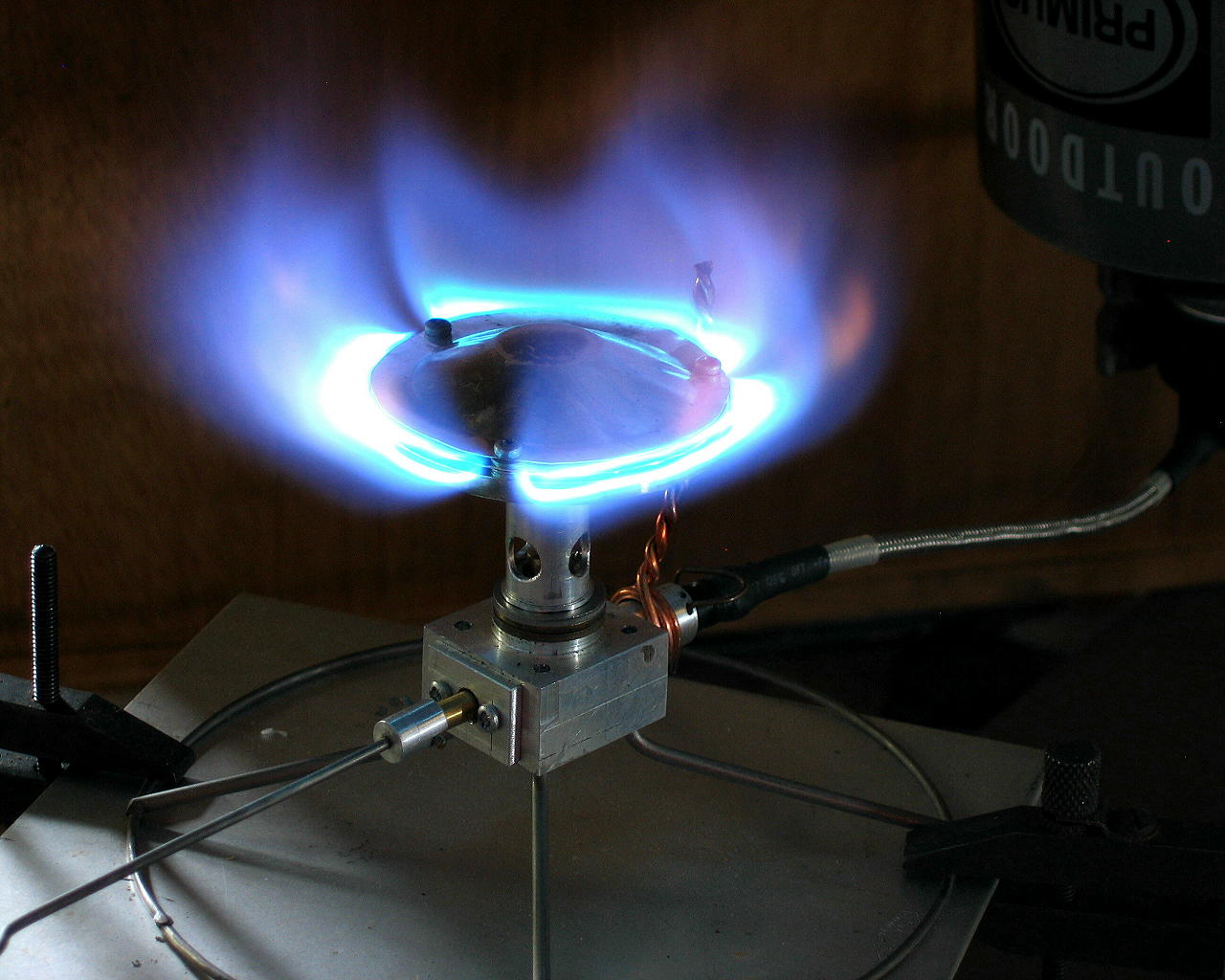
Yes, there’s a heavy copper wire heat shunt going from the flame down to the region of the heat exchanger. Heat travels down the heat shunt from the flame to the fuel coming in, helping to vaporize it. That idea (the heat exchanger) was working fine. My interest at this stage was the design of the rest of the stove, including the burner head.
Well, I fired up the stove, it ran for about 10 seconds, and then to my surprise, it stopped. I turned the canister off and stripped the stove down to see why. The groove in the Teflon rod was caked solid with dirt. I cleaned everything, reassembled the stove, and tried again. Again it lasted for about 10 seconds and then stopped. There was more dirt on the Teflon rod. This time I examined the dirt more carefully: it was dirt, not swarf (fine metal dust resulting from machining). It must have come from the canister: no other sources were possible. I had not met this kind of contamination before with a remote inverted canister stove.
Then I realized that I had just started these tests with a new canister: one of two I had recently bought locally at a lower price than normal. They were labeled “Made in China.” So I switched to a half-used Primus canister, and all was well: the stove ran fine. It would seem that the gas in the Primus canister was clean or well-filtered, but that the Chinese gas was not clean or filtered: it had a lot of dirt in it. Missing the filtration step probably saved them money during production. As roughly 99+% of the Chinese market is for upright stoves, where the dirt stays at the bottom of the canister, that may be fine for them.
In our community: read this forum thread, in which Backpacking Light members share their favorite winter and cold weather stoves.
Today
Recently, one of my customers has been having trouble with an MSR IsoPro canister: his stove has clogged several times. Not just at the jet but also at the heat exchanger. I find it very hard to believe that the dirt could have come from anywhere but the canister. From the MSR website, I see that the canister is “Made in Korea,” but what does that mean? I am quite happy to believe that the canister is indeed Korean-made. I know Korea has the manufacturing facilities for that. But where was it filled? Or where did the gas come from? I don’t know.
I was willing to believe that there might still be very fine traces of machining swarf at the jet despite all the cleaning I had done. But that the heat exchanger rod (blue cylinder in my diagram) should be covered in dirt straight after the fuel comes out of the PFA hose is too hard to explain that way. Remember: this PFA hose is American-made for use in chemistry and medical laboratories: it is clean. The way the manufacturers extrude it, it can’t help but be clean. So what to do about the dirt?
There are two ways I can think of to keep canister dirt out of the stove: block it with a filter, or prevent it from coming out of the canister. Most of this article will be about filters, but let’s cover the second option – prevention – first. It is zero-cost and pretty much zero-effort.
Prevention via tilting
The dirt is denser than the liquid fuel, so it sinks to the bottom of the canister. That is a bit like mud in a puddle. So let us look at the canister more closely.

On the left, we have the insides of a Lindal valve before crimping into a canister. Note the blue bit. On the right, we have the cross-section of a real canister (cut in half) with the blue bit of the Lindal valve added. When the canister is upright, the dirt is out of the way at the bottom of the canister. Now let us invert the canister.
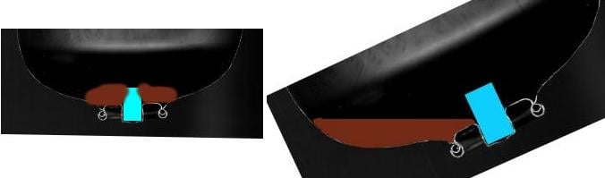
The left-hand illustration is an inverted canister with brown dirt piled up around the Lindal valve inlet. That’s how dirt gets into the stove. But what happens if, instead of casually flipping the canister upside down, we gently roll the canister onto one side and let the dirt settle? We would have something like the sketch on the right. If we avoid shaking the canister up, the dirt will settle at the lowest point, and the fuel going out of the Lindal valve should be moderately clean. Perhaps not perfect, but very usable. And that angle of tilt is dead easy to have in the field.
This principle is illustrated here with real canisters and real stoves. On the left, we have a rather unstable, fully inverted canister. This configuration would allow dirt into the Lindal valve and then the stove. I have to prop the canister up to keep it in this position. On the right, we have the canister leaning over in a far more stable position with the dirt (hopefully) below the Lindal valve
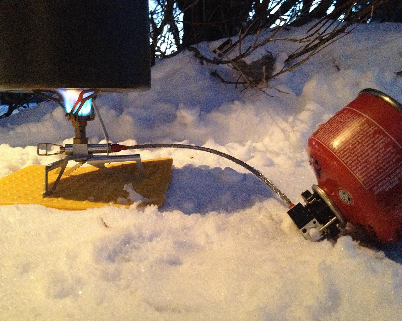
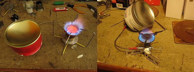
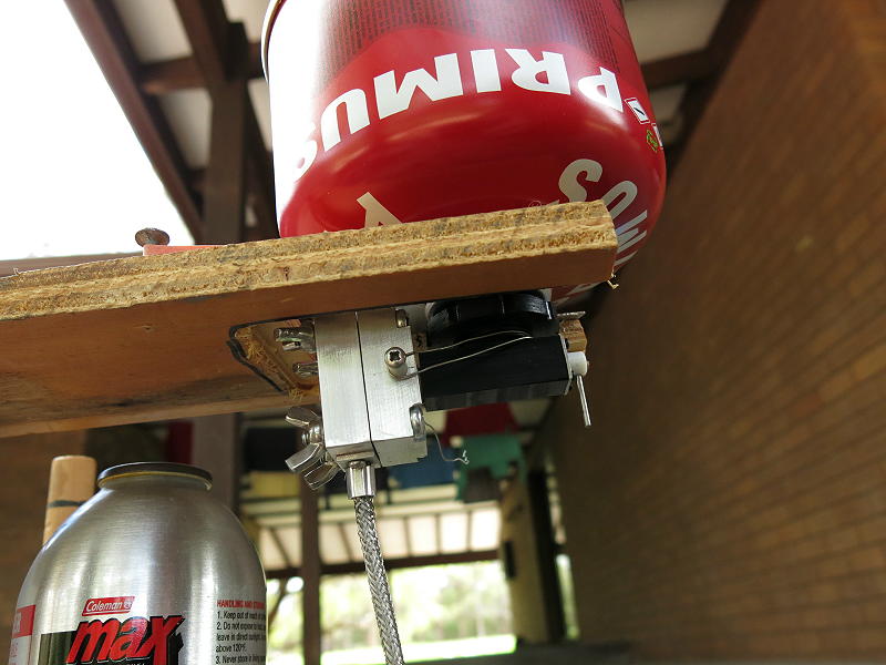
And it is not difficult to arrange a canister like this in the field either. Above is a customer photo of an early version of one of my stoves in the field many years ago. Don’t worry about the snow: propane boils at -44 °F (-42 °C) and pushes the liquid fuel down the line.
Commercial filters
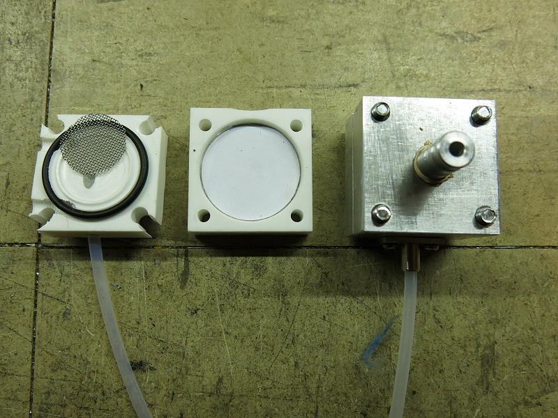
I cannot claim to be the only source of knowledge about dirt in canisters. At least one Asian commercial stove manufacturer must have had problems many years ago with dirt at the jet. They took steps to prevent clogging by placing a fine sintered metal filter on the jet’s underside. See the left-hand unit below.
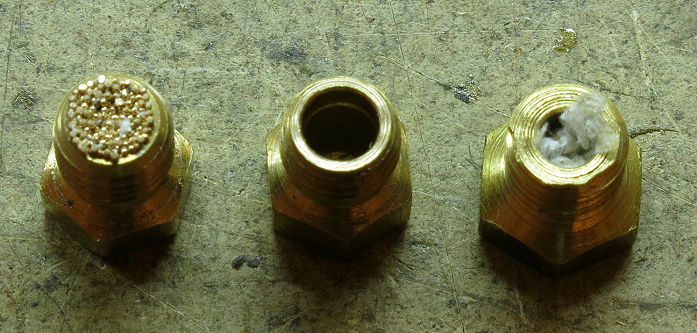
I tried to replicate this by putting some filter material in the hole in the underside of a jet I had made: see the right-hand unit. That did not work very well in practice: the paper tended to pack in and block gas flow. Putting just a little bit of tissue fluffed up in there was very hit and miss as well.
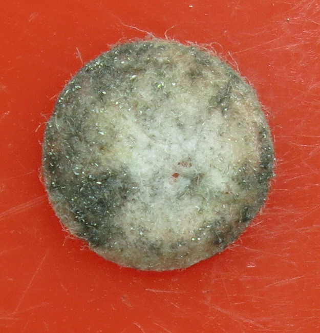
Actually, the sintered filter did not work very well either. Look closely at the top of the filter in the next photo.
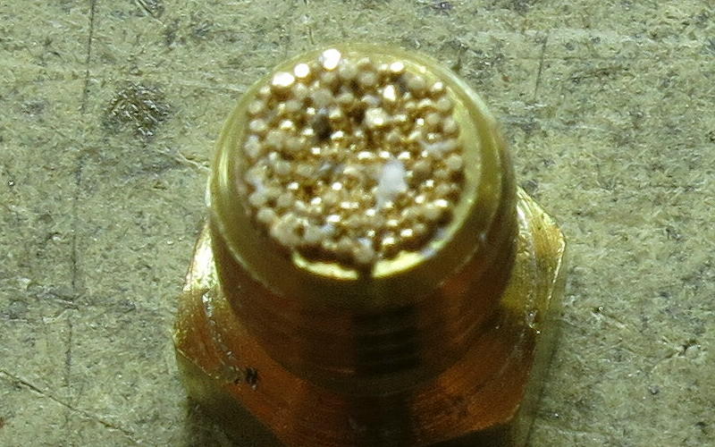
See that white stuff on top? I am unsure what it was, but it represented more stuff embedded into the sintered mass. Sure, the filter blocked any rubbish from reaching the jet hole, but it retained that rubbish too. The flow through this sintered filter had slowed to a trickle after some use, and I could not clean it very well in the lab. It would have been hopeless in the field: cold drinks and cold dinner for the rest of the trip. The unit in the middle in the previous photo shows a jet after the sintered filter had been removed, which was my temporary solution.
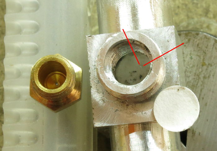
I tried putting a slightly larger filter (about 6 mm diameter) under the jet: a disk of laboratory filter paper. This filter did get dirty, of course. But a big problem was getting the filter to reliably stay in place without leaks around the edge.
I did manage to get one filter disk to stay in place in a test unit and ran it for a while. There was a lot of dirt collected (the vague dark areas everywhere). In addition, there was a fair bit of shiny aluminum swarf. That stuff is really fine: the filter disk is only about 6 mm in diameter. Machining aluminum can leave a certain amount of fine aluminum dust, which sticks to the bulk aluminum. The stove body I was using was an experimental one I’d made just for testing, and I had not cleaned it before use. After this incident, I seriously upgraded my cleaning process.
But what is not covered by any filter located at the jet is anything else upstream from the jet. As I mentioned previously, an early Teflon heat exchanger rod had become caked by dirt upstream of the jet. I needed something better.
Refilling / filtration unit
At the same time, I was also playing around with refilling some old Powermax canisters. The aluminum Powermax cans are much lighter than the steel screw-thread ones (and the Coleman gas in them originally was very clean too). I like them. So I decided to add a filtration stage to this refilling system. I show bits of two units below.
I made up a filter unit using a larger filter paper disk with a stainless steel mesh for support. Good chemistry lab filter paper: Whatman 540, 8-micron rating, sealed around the edge. The unit plugged into the canister connector on the donor canister in place of the hose connection. I suspect that paper coffee filter material would work fine in place of the Whatman stuff, and also probably paper vacuum cleaner bags. Both are readily available and very cheap. Any dirt fine enough to get through those paper filters would sail through the jet unimpeded.
I have refilled quite a few Powermax canisters like this. I had to monitor the weight of the receiving canister to avoid overfilling it, of course: a load cell and associated electronics did that. To explain: if one fills a canister right up, so there is no vapor space left, there is no room for expansion. The canister can explode if it gets warm later, and the liquid fuel tries to expand but can’t.
I got some dirt on the filter paper, but not much. That was (I think) because I was using Primus canisters as the donors (see photo above), and they are filled in Europe, not in China. I have not had any problems with Primus canisters. Anyhow, the refilled filtered Powermax canisters have never given me any problems.
This tactic worked, but it was a bit complex, and it does not help the average user who does not have the workshop facilities I have. What I really needed was a simple filter to go inline – especially for my stoves.
Inline Filters
My ideal solution would be something that took out any dirt before it got into the hose – for two reasons. The first is that I have also seen blockages in the hose once or twice, and they can be quite messy to clear at home and very difficult to deal with in the field. One needs about 300 mm of 1 mm titanium wire to do the cleaning, and who carries that in the field? The second reason is that the stove body can get hot (allow for 392 °F / 200 °C), which could damage many filter materials, especially any paper filters. So a filter back at the canister connector (which stays cold) seemed a better idea.
Member Exclusive
A Premium or Unlimited Membership* is required to view the rest of this article.
* A Basic Membership is required to view Member Q&A events

Discussion
Become a member to post in the forums.
Hi Eric
I suspect it is not the stove but the canister that creates the problem.
What were they using?
Cheers
Perhaps I should mention that the few V6 stoves still available for sale have all been modified to incorporate the filters. I was able to reduce the length of the 8 mm hose connector as indicated in the article. That means they do not need any spacer.
Yes, my stoves have also been modified this way. They continue to work fine. That said, the filters in them have not caught a lot of dirt recently because I use filtered gas in refilled canisters, as the article mentions.
Should I go out and BUY some dirty Chinese canisters for testing? Nah.
Cheers
Become a member to post in the forums.