
DIY Backpacking Stove: An Ultralight Vortex Burner for Winter Backpacking: Series Outline
- Part 1: Background and Theory
- Part 2: Research and Development
- Part 3: Mechanical Design
- Part 4: Lab & Field Testing
- Part 5: Pot Support
Part 4: Lab & Field Testing
Introduction
What we have so far is a functional but relatively untested ultralight winter stove. To be sure, we tested the burner chamber and splash plate well in Part 2, but those were simple tests with a narrow focus. Part 3 covered a lot of design, development and some field testing of a prototype. It did not cover very much routine testing of production models, however. You need a whole lot of testing to get a satisfactory and reliable stove in the field (a lot more testing than most software ever gets too).
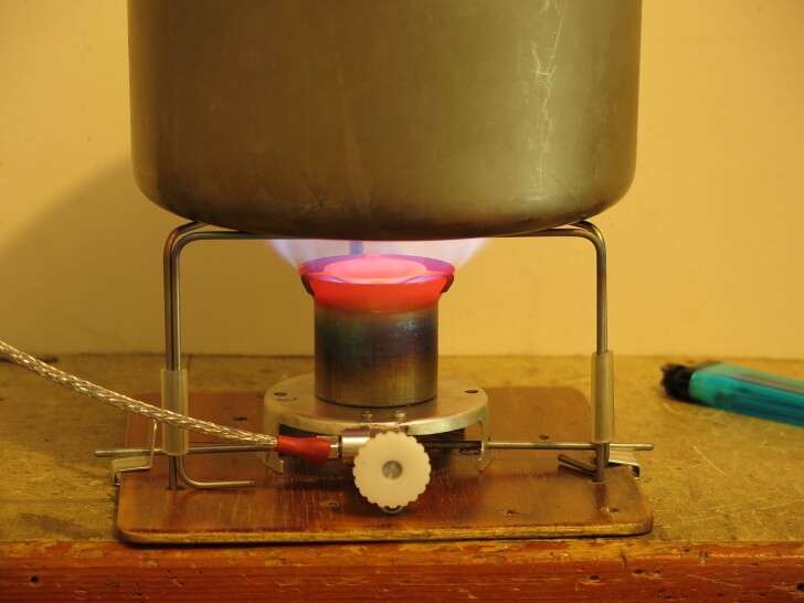
So in this Part 4, we will cover a whole lot of lab and field testing, and some of the gremlins found along the way. There were a few heart-stopping moments when Murphy announced a continuing presence, but fortunately, Murphy was kind.
Needle Valve
I gave basic details about the needle valve in Part 3. The long shaft of the valve and the matched bore in the stove body form a very effective heat exchanger, such that you do not need a “preheat” tube over the top of the stove. If anything, I had to take a fair bit of care to minimise the way the stove body heated up. I mentioned some of this in Part 2.
But there were more issues. Given that the bore is 13/64 in. (5.1 mm), and that we want a thin film of fuel running down the inside, a long needle of about 3/16 in. (4.8 mm) diameter seemed suitable. That gives a .006 in. (0.15 mm) clearance all around in the ideal case, which is reasonably “thin film.” All that is fine, but there were problems when the stove was running on a gas feed, one of which was that the power was very limited. I didn’t mind the power being a little limited with a gas feed. This model is meant to be a liquid fuel stove after all, but the limitation seemed a bit too severe. However, the needle valve and the jet were clean.

Eventually, I found the problem, and the above photo and diagram show it. Fuel comes down the inside of the (grey) PFA hose to the (pink) stove body (see diagram on right), and makes an acute right angle turn where the flow goes from the inside of the hose to the inside of the needle bore (red circle). The shaft of the needle valve (light purple) goes across the hole in the socket which the hose goes into (see photo on left). It effectively blocked the gas from getting out of the hose and into the “thin film” region (yellow). The entry into the bore was the very small circle (1/8 in. or 3.2 mm diameter) at the end of the hose socket. This acute right angle bend in the flow path to the thin film region was putting up too much restriction. I had to enlarge the bore around the needle valve in that region, and only neck it down later. That meant making the red circle surrounding the yellow region (i.e., the bore) just 1/64 in. (0.2 mm) bigger in diameter. That does not sound a lot, but the clearance was only 1/64 in. (0.3 mm) to start with. That increase almost doubled the clearance in that region. This was easy, and it worked fine.
Control vs. Shut-Off
The control valve (needle valve) is for controlling the flow of gas. It is not for shutting off the flow of gas completely, as leaks are always possible. (For instance, you could have dirt and waxes collecting at the tip of the needle valve). To shut off the gas flow completely and make the stove safe, you must use the safety on/off valve back at the canister connector. When “off,” that lets the Lindal valve inside the canister shut off the flow. A solid spring and the pressure of the gas create the sealing. The needle valve cannot match that.
Granted, if you get dirt on the seat of the Lindal valve, you may have a problem. The canister may then sit there leaking away, even when you have disconnected the stove. If this happens, you need to clean the Lindal Valve. This can be done by inverting the canister and briefly poking the Lindal valve with a solid rod such as a Ti wire tent stake. A good blast of liquid fuel will come out, and this may clean out the dirt. Needless to say, you must do this outside, well away from any flames! BPL takes no responsibility for your doing this.
All that aside, it would be nice to be able to shut the stove down at the needle valve just for a few minutes – while serving up dinner for instance. So having the needle valve shut the flow off is still highly desirable. However, on a couple of early production units, the needle valve would not shut off 100%. A tiny leak remained.
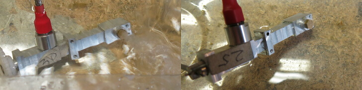
I test this with compressed air rather than canister fuel (for both safety and cost) and underwater. You can see bubbles very easily. I test all my stoves this way. On the left, the needle valve is open a bit, and there is a blast of air coming out of the jet. (This exercise can get a bit wet, but I did it in mid-summer). What I wanted is shown on the right: no bubbles at all when I gently close the needle valve. Achieving this just requires very clean machining of the valve seat (at the bottom of that very deep hole in the stove body) and a suitable profile on the needle valve tip. What took time was working out just where the problem was. Everything is so obvious in hindsight. In brief, then: a rough valve seat does not work too well.
Overheating – again
Everything was going fine, with the first couple of stoves working nicely. But in the first real production batch, things went a bit wrong. (They have to; it’s a fundamental law of reality). The stove body on one unit got far too hot: “pzzzt,” over 212ºF (100ºC). This was a bit of a puzzle for a while, as it was not happening with the first couple of stoves, and other stoves in the production batch were not as bad.
I tried putting some insulation between the aluminum stove body and the aluminum stove base, but that did not solve the problem. What was worse, the stove base plate was also getting well over 212ºF (100ºC). Handling the stove while it was running was “unwise.” Deep thought did not solve the problem, so I went for a walk with my wife instead. I let my subconscious stew over the problem for a change.
On my return, I realized that instead of looking for the problem, I should be looking at why this stove was different from the first couple. That eliminated a lot of possible causes and complex solutions. What follows is probably rationalization rather than what happened in my mind. I realized several things altogether:
- The top of the burner chamber was glowing red. That meant it was above 1472ºF (800ºC), so the bottom rim of the burner chamber could easily be around 752ºF (400ºC).
- Since this problem was not happening on the first prototype, the problem was not due to excess heating by the flames on the inside. If it was, the first stove would have been similarly affected.
- The several hundred degrees temperature differential drives the heat transfer from the burner chamber to the aluminum stove base plate. The heat transfer is limited by the contact area between the two. (I had already reduced the contact area between the stove body and the stove base plate to a minimum to limit heat flow).
- The main difference between a production unit and the first prototype was that I had hammered the rim on the burner chamber over by hand on the prototype. It was not dead smooth.
Maybe the slightly lumpy rim on the prototype was making very little contact with the stove base plate compared to the much smoother rim from the hydraulic press, and so conducting very little heat. Maybe. How should I test this idea? I didn’t want to put insulation material of any sort in between rim and base when those flames were roaring around (it would char). Maybe a steel washer (or three) could be put between them.
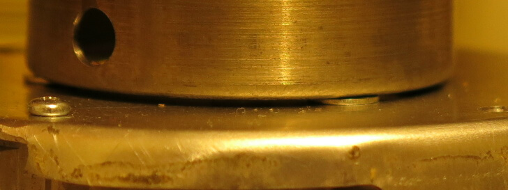
Three small steel washers were added to the M2 screws to sit between the titanium rim and the aluminum base plate. They were too large to go through the keyholes in the stove base plate. With great hope, the stove was lit. The stove body got warm, but not too hot; most of the heat flow had been blocked. The extra air flow through a 1/64 in. (0.5 mm) wide slot did not change things.
Filters
With a small jet hole there is always the risk of a blockage, so the accepted practice is to instal a filter under the jet. That seems to work very well with many stoves. However, when field testing the prototype stove in the mountains, I found I kept getting blockages of some sort despite the filter. The flames would go all weak and wobbly. At the same time, I did notice some oily stuff accumulating on top of the jet.

The photo here shows three different sizes of jets, from different stoves. The ones at the back have a 15/64 in. (6 mm) thread, and one of them has a tiny bit of tissue stuffed in the hole as a filter. The middle row shows two rather small jets with an 11/64 in. (4.5 mm) thread. Fitting a bit of tissue into one of these is difficult. The front row shows the very small jets I am making for this stove, with a 5/32 in. (4 mm) thread.
Back home I tried various sorts of filters under the jet, but they all seemed to block up quite quickly with some wet, oily stuff. Part of the reason for that I am sure was that the little bits of tissue or filter paper had to be so very small to fit into the jet socket. A very small amount of liquid could wet out the whole filter so easily. On the other hand, a 5/16 in. (8 mm) filter disk inside the canister connector (i.e., upstream of the vaporization point) was not showing any problems at the time and was enough to block dust. In desperation (in the evening in the field at 5577.4 ft. [1,700 m] wanting dinner I might add) I removed the tissue filter from under the jet and left it out. There were no further problems for the rest of the trip. Clearly, a “wet” filter can easily block the jet. So having a filter under the jet is now “out.” It is officially a “bad thing.”
Member Exclusive
A Premium or Unlimited Membership* is required to view the rest of this article.
* A Basic Membership is required to view Member Q&A events

Discussion
Become a member to post in the forums.
Companion forum thread to: DIY Backpacking Stove: An Ultralight Vortex Burner (Part 4: Lab & Field Testing)
In part 4, Roger Caffin tests the vortex burner in the lab and in the field as a solution for an ultralight winter DIY backpacking stove system.
Become a member to post in the forums.