DIY Backpacking Stove: An Ultralight Vortex Burner for Winter Backpacking: Series Outline
- Part 1: Background and Theory
- Part 2: Research and Development
- Part 3: Mechanical Design
- Part 4: Lab & Field Testing
- Part 5: Pot Support
Part 3: Mechanical Design
Introduction
In part 1 of this series, I outlined what might be called my dream for a remote-canister Vortex Burner Stove – my solution for an ultralight winter stove. In Part 2 I covered the design and manufacture of the titanium vortex burner chamber. In this Part 3 we go into the mechanical design of the stove body and the needle valve, and then we delve deeply into the flame shape and the fuel/air requirements of a vortex burner. If you haven’t read Part 1 and Part 2, do so first, because all the background to this article is given in those Parts, and is assumed here.
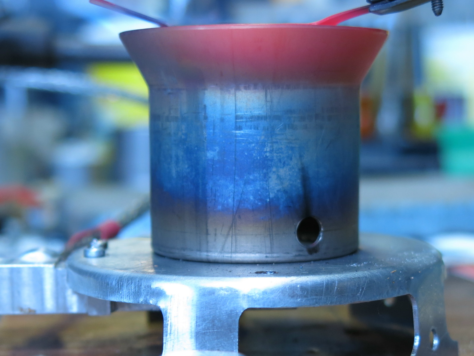
Stove Body
By “stove body” I mean the bar-like lump of aluminum which goes between the hose from the canister and the jet inside the burner chamber. You will have seen several versions of this in Parts 1 and 2. This has to provide some services listed below.
- It has to support the jet in the middle of the base plate, at the bottom (this is pretty simple).
- It has to be the connection point for the hose.
- It has to have the valve seat right near the jet, in the gas flow.
- It has to hold the screw thread for the needle valve somewhere far from the jet.
- It has to act as a heat exchanger for the liquid fuel coming out of the hose and the inverted canister.
- It has to get warm, but not so hot that the two Viton O-rings at the outer end get damaged.
A complication in the design was that I found I needed to machine all six sides of the bar, plus bore out the insides. This is not simple router-style machining like cutting out a pattern in 3-ply – but that is part of the fun with CNCs. The secret is to design suitable machining jigs and feasible machining sequences.
Needle Valve and Heat Exchanger: Theory
As you can see from all the photos, the hose connects to the stove body some distance from the jet, so the fuel has to go up the inside of the stove body, through a needle valve for control, and out through the jet. Following on from my success with the internal heat exchanger in the previous Winter Stove, I could see no reason not to do this again. That is, there will be a central bore down which the fuel will flow, but that bore will be largely filled up by the needle valve, so the fuel travels as a thin film. This is good for heat transfer and fuel vaporization.
However, there are manufacturing differences between the two stoves. In the previous design with a common upright burner, the needle valve is short and easy to make, and the needle valve seat is near the “surface” and is easy to drll. In this design, the needle valve itself is long and slender, and the needle valve seat is way down at the bottom of a long bore. Typically the hole for the needlepoint might be about 1/16″ (1.6 mm). The idea of trying to send a very long 1.6 mm drill bit down a >2″ (50 – 60 mm) hole and hoping to get a clean and accurate hole dead center at the bottom is the stuff of dreams.
However, I found a cunning way to do this. Many of you will recognize what a “center drill” is: it’s a solid rod with a short, small drill right at the tip. I found a source for a very long (3.94 in. [100 mm]) center drill, with a .2 in. (5 mm) shank and a 1/16 in. (1.6 mm) tip. That’s a very long center drill, but the 5 mm shank of high-speed steel was quite solid. By drilling the bore in the stove body to .2 in. (5.1 mm) ID, I could drop this 5 mm center drill down the bore and make a short 1.6 mm diameter hole at the bottom, leading into the jet socket. Given the design of a center drill, that also meant the small hole centers at the bottom of the bore, which meant (in theory) that it should seal properly against the needle. The 50-micron radial clearance went well with a drop of oil.
Did the design for the long needle valve come before I found the center drill, or did seeing the long center drill inspire the design of the needle? I have no idea.
The profile of the tip of the needle matters. If it is blunt, then a quarter turn of the valve will probably create enough clearance to take the stove from “off” to “full bore,” which is far too abrupt, so the tip has to be tapered. But if it is too tapered it can jam in the hole when you shut the stove down. A special profile with a shoulder is needed. That’s normal for most commercial needle valves, some of which can be obtained with specified flow control profiles.
That sounds very fine in theory. The practicalities were another matter, and sorting them out took me some time. The first one or two needle valves worked fine, but then I ran into some problems. A major problem with some early needle valves I made was that they could not shut the gas off completely. Something was very wrong way down at the bottom of that long hole. Resolving that problem is left to Part 4, where I look a bit more at field testing of production models.
There were a few other complexities at the outer end of the needle involving the O-ring seal and the screw-thread needed there, but they were standard engineering stuff. For instance, you don’t push O-rings over freshly-machined threads unless you want the O-ring surface damaged. O-rings with bits out of them don’t seal the fuel in. And the bore into which you put an O-ring had better be very smooth if you don’t want the O-ring to be steadily chewed and ground away. Polishing some bores was necessary.
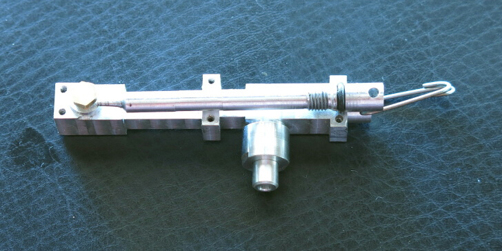
The design shown in the photo above is workable, but making it in a reliable manner was a different matter. In fact, it turned out that making the needle was one of the most difficult parts of the whole exercise, and that is not counting the problem with the shut-off. You see, the needle is only .19 in. (4.8 mm) in diameter, but it is about 2.0 in. (50 mm) long – look again at the photo above. That length of thin rod flexes when I machine it, even when I use a hard aluminum alloy. Getting a uniform and correct diameter (to about .002 in. or 0.05 mm) over the full length of the needle and the correct tip profile at the end required a few machining tricks and several different attempts (or CNC programs) before I was happy. Note that since the tip of the needle has a crucial but tiny “needle” profile, using a tailstock is not a viable solution here.
Member Exclusive
A Premium or Unlimited Membership* is required to view the rest of this article.
* A Basic Membership is required to view Member Q&A events

Discussion
Become a member to post in the forums.
Companion forum thread to: DIY Backpacking Stove: An Ultralight Vortex Burner (Part 3: Mechanical Design)
In part 3, Roger Caffin discusses the mechanical design for the vortex burner as a solution for an ultralight winter DIY backpacking stove system.
Become a member to post in the forums.