DIY Backpacking Stove: An Ultralight Vortex Burner for Winter Backpacking: Series Outline
- Part 1: Background and Theory
- Part 2: Research and Development
- Part 3: Mechanical Design
- Part 4: Lab & Field Testing
- Part 5: Pot Support
Part 2: Research and Development
Introduction
If you haven’t read Part 1 with all the background, do so first. In that part, I first discussed why I wanted to embark on another stove project, a Vortex Burner stove project. Then I looked at various early Vortex Burner stoves I made and discussed all the things which I thought were wrong with them. The analysis was fairly light at that stage. Most of what follows comes after I had made and sold my first version ultralight winter stove, and my skills and equipment were increasing.
Part 2 will cover some detailed research and development on the basic Vortex Burner chamber, which I saw as being the most crucial part of the project. The chamber turned out to have a few kinks along the way. I will cover other parts of the design in later parts of this series – with their kinks. I will not be covering the canister connector and the hose as they are exactly as described in the previous series on my first Ultra-light Winter Stove.

One thing I had better mention here before we get going: figuring out what I wanted to build was easy. Figuring out in general terms how I was going to build it was not too bad, but the devil was in the details. Making it manufacturable, rather than be just a one-off, was a key requirement and that was also “interesting.”
Vortex Burner Chamber Design
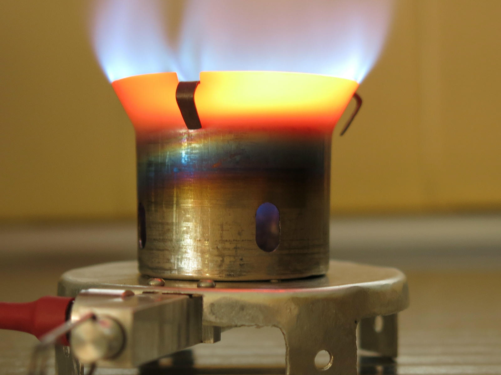
The part shown is the most visible part of the stove. It features a base plate, the round burner chamber itself sitting on the base plate, and a “splash plate” sitting on top. The splash plate is what stops the jet from going straight up in the air, and it was a bit more tricky to create than I had expected. The design I finally settled on is very close to what I showed in Part 1 of this series.
The burner chamber more or less shapes the rest of the design and the 1.5 in. (38 mm) Ti tubing I had in stock dictated that. It wasn’t a bad thing mind you, as I had bought that size of tubing for this project in the first place. It seemed to be (about) the right size for the stove power I was expecting. So I’ll start with the chamber itself. It has a flare at the top, a straight bit in the middle, and a rim at the bottom.
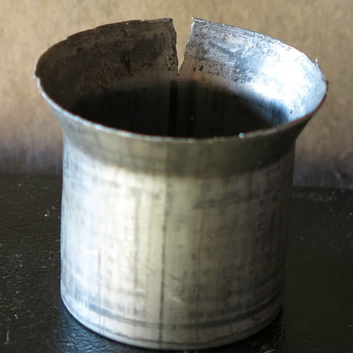
I decided on an approximately 26-degree flare at the top, mainly because the way the flames came out “looked right” during early prototype testing. I tried other angles, but the narrower ones seemed to choke the flame a bit while the wider ones did not seem to improve things. We can skip at least six months of trials and frustrations here, if not more. Anyhow, pushing the tubing too much greater than a 26-degree flare threatened to split the tubing, as shown here. I decided that the top of the 26-degree flare would be 1.9 in. (48 mm) in diameter.
The middle bit is dictated by the overall height I wanted. I experimented with low versions and tall versions and ended up with something about 1.6 in. (40 mm) high. I settled on an allowance of about .2 in. (5 mm) for the turn-in on the bottom rim. That is enormously strong and wide enough for the M2 retaining screws, which I will return in Part 3.
In practice, I allow a shade more for the flare than I need and then I trim the tubing to the exact size on my manual lathe. That only takes a few minutes per unit. An existing mandrel completes the part-holding. It means the finish at the edge ends up very nice and clean and fits the splash plate neatly. It is worth the slight extra effort. I don’t bother machining the inside of the bottom rim; it is not exposed.
In addition to the walls, there is the splash plate on top of the burner chamber to make the fuel/air mix recirculate in a vortex. Commercial stoves usually have a dished splash plate. They make dished splash plates out of brass sheets which are easy to shape. A big thump and you finish. I wanted to use the much lighter 6Al-4V Titanium sheet I had – which is much harder to shape. In fact, at the start (in the early days) I found the 6Al-4V alloy was simply too hard to shape with my available technology. As a result, I decided (early on) that the splash plate would (have to) be flat, not dished. That would be so much easier to make, although, in the end, it was not quite that simple. We will come back to this later.
Making the Burner Chamber
So the basic burner chamber design was “settled,” and I already had most of the needed tooling (dies and clamps) for the job from my early experiments; I just had to figure out how to make the flare and the rim smoothly and efficiently. Considerable forces were involved, the drill press was hopeless, and my poor vice was not a good solution. Hammering was just not elegant enough – see the photos in Part 1 for that. The simplest solution was to replace the vice (which did work) with a small hydraulic press, assuming it could generate enough force. After some experiments with a press that belonged to a motor mechanic friend, I bought a small bench-top 10-ton hydraulic press locally. The sales rep assured me it came fully assembled. It turned up quickly, but it was about as assembled as an IKEA prepack, and in a similar flat box. Score one for sales rep knowledge (and my doubts). There were no problems really; it went together easily. I mounted it up on a solid bench.

The flared top end was made using my existing male and female steel dies (turned in my lathe), and it took about 2 tons of force to get the flare snugged into the die. As the two parts of the die both rode on a central core, alignment during pressing was close to perfect. Doing it without the central core guide was not successful. The flare always went off-center, sometimes badly. The red line points to the titanium, the green line points to the female/external part of the die, and the blue line to the male part. As the metal stretched during the flaring, it came out smooth anyhow, with just a few ripples at the top edge. These were later turned off in the lathe.
The bottom rim (going inwards) was a shade more complex. I had to get the tube to collapse inwards without creating significant crinkles. And yes, at the start there were lots of crinkles. In the end, I had to use a starter die with a 60-degree taper to get the edges going a bit inwards. I then used a 45-degree taper die to get the rim really turned inwards enough. Finally, I used a flat steel die to squash the rim down to the flat surface of the core on the inside, ironing out any wrinkles. As I did want a “flat” surface I had to go up to 6 tons of force. That was well beyond what my cast iron vice could manage (so was the 2 tons for the flare, really), but the whole process was quite simple with the hydraulic press. I followed the steps in my worked-out script. If I did not follow the script carefully, I risked crumpling the other end of the Ti tubing. One learns and hides the failures. It was interesting how all the wrinkles “went away” when squashed with 6 tons. So now I had a manufacturable burner chamber.
The dies started out as some variation on “mild steel,” if there is a such a thing. (In Australia what they call “mild steel” can be any scrap they had lying around at the smelter; it is really very variable stuff). There are some marks on the machined surfaces where the titanium slides over the steel, but these are not yet serious. If the marks get bad, I will have to remake all the dies with a harder steel, but for the moment, a little EP grease works fine. The hardest part of making better dies is buying small quantities of good steel locally. If you want several tons of it, no problem.
So to summarize: the hydraulic press lets me produce quite nice burner chambers. In fact, it is interesting just what sorts of things you can do with a good press. My manual lathe provided the final polish. Next, I needed a base plate and a splash plate.
The Burner Base Plate
In Part 1 I showed a very early triangular Ti base, with edges folded over for stiffness. That proved to be a bit of an overkill, so I switched to a circular base made of .03 in. (0.8 mm) thick 5251 aluminum sheet. But such a thin aluminum sheet is fairly flexible by itself, so I decided to give it a rim. It was not hard to machine a round aluminum disk, clamp it between two machined circular steel plates, and hammer the edges over to make a small rim – which stiffened the whole base wonderfully. 5000-series aluminum is good for this bending and forming. Some problems immediately became apparent when I assembled the first prototype. This base is going to have to sit up in the air a bit. It has to stay off the ground, because a) the stove body is underneath the burner base plate (explained later); b) you need room for a handle on the needle valve, and c) the hammering was slow and uneven, and the result looked rather amateur.

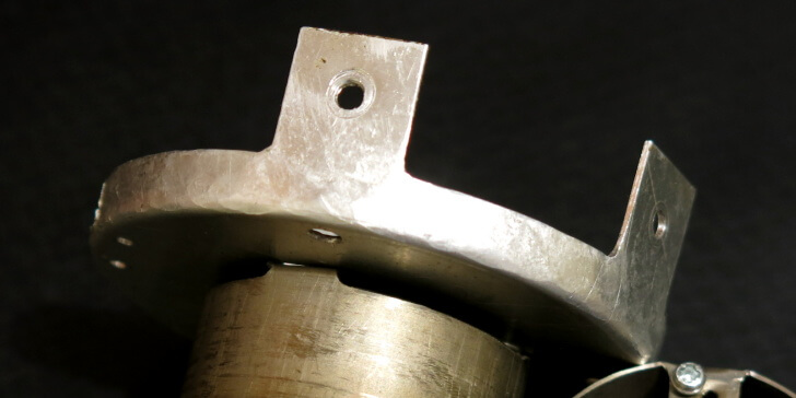
First step: get the stove up in the air a bit. I very briefly experimented by using bolt-on legs, but they were boring, clumsy, crude, heavy, and added a lot of complexity to the project. The thought occurred to me that maybe I could cut the nominally circular burner base plate out with the legs already sticking out as part of the rim before I hammered the rim over. Machining such a shape by hand was ridiculous, but doing it by CNC was easy. I could probably even stack up many layers of aluminum and very accurately cut 6 – 8 bases out at once. Production! That’s what led to the photo here.

The first few bases I made had four very simple legs, arranged symmetrically as shown here on the left. I eventually found that this arrangement was not all that stable, as the legs were not very far from the center-line. The stove could tip sideways a bit too easily for my liking. I could have rotated the four legs 45 degrees relative to the solid aluminum stove body and cut one leg off to make room for the stove body. Instead, I switched to five symmetrically arranged legs, which greatly improved the sideways stability. I then machined off one of the legs to make room for the stove body to stick out (at the front). Well, it works fine, and it was easy to program for the CNC – and it is more stable too.
But I was still hammering these rims over by hand, slowly and painfully and a bit erratically. Late one night as I was going to sleep, the image of the stove base pressed into shape while in my nice new hydraulic press came into my mind. As the inner die was driven down by the ram through an outer die, the legs just popped up from the flat. (Of course, we dream in color video these days). Would this work? Next morning I took a solid lump of old Australian hardwood (and that stuff is hard and tough) and bored it out into a suitable female pressing die. To help the aluminum fold over at the rim more uniformly I made the edge curved rather than sharp. To help the flow of the aluminum over the timber I lubricated the curved edge of the die with hard paraffin wax. That hopefully, would stand up to the forces involved a lot better than oil or grease.
Member Exclusive
A Premium or Unlimited Membership* is required to view the rest of this article.
* A Basic Membership is required to view Member Q&A events

Discussion
Become a member to post in the forums.
Companion forum thread to: DIY Backpacking Stove: An Ultralight Vortex Burner (Part 2: Research and Development)
In part 2, Roger Caffin explains the research and development behind the vortex burner as a solution for an ultralight winter DIY backpacking stove system.
I don’t think IR will reflect off the burner chamber.
Maybe a parabolic shape of the chamber would emit a little more up towards the cooking pot, but the IR that’s absorbed on the sides isn’t wasted – it heats up that metal which then re-emits.
I bet burning efficiency is the main factor.
And, I wonder what Roger thinks of Trump? Brexit?…
Hi James
Yes, I do understand about IR radiation. (Retired PhD research physicist, remember.)
The parabolic shape – easy enough to make in drawing brass if you have a large press. After all, that’s how most of the commercial Vortex Burner stoves do it. That was the only viable technology available to Primus when they started making such stoves, way back when. But try making that shape in Titanium (which is (what I wanted to use). I think there are three ways you could do it:
* Forming red hot Ti (and I do mean RED hot)
* Machining out of solid (the time and cost …)
* 3D powder metal laser sintering (the cost of such a machine)None of these are commercially viable in my workshop!
The thing is, the Burner Chamber design I have ended up with (as outlined in Part 1 & 2) WORKS, works well, and is manufacturable by me. The rest of the design will be revealed in better detail in the forthcoming Parts of the series.
Cheers
Hi Jerry
The IR will reflect off the Ti metal, and be absorbed and reradiated. However, it doesn’t matter, as ultimately the energy has to come out of the stove. Efficiency is fine, and the burner can simmer gently as well as roar.
Cheers
Roger, No, you missed it. You can slit the side and draw the rest.
Sort’a like working with sheetmetal to form a curve, ‘cept you are working with a cylinder.
In practice, you can simply make a slit then die it down to the correct diameters in a press. Of course you have to allow for the thickness of the metal, over-bending as needed and possibly inserting a steel screw/rivet to hold it (but a little leak is OK.) As I mentioned it will act as a vortex in the combustion chamber. insulating the sidewalls also. High heats will eventually degenerate the Ti. Centering the bends will be the worst of the problems.
Hi Jim
No, I didn’t miss it. I have already tried doing what you suggest, and I have to report that it ain’t easy! It is easier to form the alloy used in the tube than the 6Al-4V alloy, but only slightly. Very large forces are still needed.
I would have to develop new steel dies for this, and hope that a 10 ton press is sufficient for the forming job. I have some reservations, but maybe. Many months of work would probably be required.
I would have to ‘seal’ the joint line to prevent local oxidation and corrosion. While the surface of the Ti tubing does develop a very effective protective oxide layer very quickly on open surfaces (humidy helps, believe it or not), Tim Clarke’s experience is that tiny pin-holes through the metal do ‘burn’ out rather quickly. I suspect that the butt joint on the surface would behave in a similar manner to tiny holes. So, how to seal that joint (or several joints)?
I don’t think there are any ‘sealants’ which would handle the high temperatures AND the thermal cycling.
I don’t think ordinary spot welding would work here.
You can’t braze this stuff.
MIG welding might work – after a lot of practice at sheet metal welding, but I don’t have a MIG welder and I have no experience there either.
An electron beam welder would probably work, but I don’t have one (and cannot afford one either).
But more to the point, what would the design gain?
I have superimposed the parabolic design (red) onto the parallel tube design (black) here. The volume difference in the corners is small – remember that the OD of the tube is only 38 mm. The flames are kept out of the corners to a large extent by the flow of air in through the inlets as shown. The main part of the flame vortex is up near the splash plate anyhow, although burning up the middle certainly happens.
So – given all this, would the behaviour of a conical/parabolic burner chamber be all that much different from one made from straight tubing? I have to say I cannot see that there would be any real gain for all the hassle.
But I might be wrong. Perhaps someone might like to make some parabolic chambers for testing? I would be very willing to give them a test!
Cheers
Roger,
Have you seen these?
I am pretty sure that they are a CP Grade and if so it would be pretty easy to reshape. 38 mm at the top and 10 grams is a good starting point. Best wishes.
http://toaksoutdoor.com/titaniumshotglass.aspx
F AS C I N A T I N G
No, I had not seen them.
Some of the Chinese titanium fabricators are getting VERY good. They seem to be able to make stuff which can not be made in USA. Does anyone worry about this?
The shot glasses are more expensive than the tubing, and I would have to develop a new set of dies for the flaring. But very interesting all the same. I have copied the page for some consideration, thank you!
Cheers
Roger,
“I would have to ‘seal’ the joint line to prevent local oxidation and corrosion. While the surface of the Ti tubing does develop a very effective protective oxide layer very quickly on open surfaces (humidy helps, believe it or not), Tim Clarke’s experience is that tiny pin-holes through the metal do ‘burn’ out rather quickly. I suspect that the butt joint on the surface would behave in a similar manner to tiny holes. So, how to seal that joint (or several joints)?”
I do not believe so. As I said, a small screw will work on the overlap pinning the two bends together. OR, you could leave it loose and create a vortex air inlet. Two might work better than one. This will cycle around the burner (by centripetal acceleration) cooling the whole burner. I would guess about 200C solving the overheat problem. IR would be reflected up and out along the whole chamber, increasing efficiency rather than just dumping heat secondarily. Welding, brazing become superfluous. Necking it down, and centering it, become the only real problem.
Yes, I read Tim’s articles. I believe his burnouts were caused by localized combustion at the surface. Your stove does not do that. It burns in a donut…well a vortex. Almost all the combustion has happened before the heat has rotated around.
Hum … interesting ideas.
I suppose it’s me who is expected to do all this too? :-)
I will think about it for a bit, especially the dies needed. Mind you, that Toaks shot glass is also an interesting idea.
In the meantime I have to replace a substantial part of the roof of my barn/workshop. It’s probably >100 yrs old, the iron has rusted so the roof leaks, and some of the battens are a bit light and a bit old. The rafters – are straight sapling trunks – well, mostly straight. My CNC lives under al this. Ah well.
Cheers
One of the photos in the article shows a layer of red fibreboard between the Stove Body and the Stove Base Plate. It was effective, but I have not been able to find where to buy the stuff today. What is shown is some of my ‘old stock’ from 20+ years ago.
However, while I cannot find bulk red fibreboard for sale, I was able to find small washers made of red fibreboard (on eBay of course). So now I put 4 of these between the body and the base plate, as shown here.
Close examination of the stove body will show that it has been machined away for most of the contact region between it and the base plate, to reduce the contact area as well. Now the body is attached to the base plate with 4 screws through the red fibreboard washers, and only those screw regions are anywhere near the base plate. In effect the screw regions form small ‘bosses’. The combinaton of reduced contact area and fibreboard washers seems to work fine. The Base Plate can get over 100 C, but the Stove Body only gets ‘hot’ – which is essential to vaporise the fuel of course.
Cheers
Become a member to post in the forums.