Background
This article describes the development of my 4th generation of Remote Inverted-Canister Winter Stoves. You can find articles about the previous versions here at BPL in the series’ Evolution of a Winter Stove (5 parts) and DIY Backpacking Stove: An Ultralight Vortex Burner (5 parts).
It all started years ago when I was contemplating the weight of a number of commercial remote canister stoves, and wondering why they had to be so heavy. In many cases, it seemed as though someone with little knowledge of stove engineering had just thrown bits together with no regard for either weight or elegance. Some of the results were clunky, and others were just weird.
At the same time I was looking at some of the massive pre-heat tubes found on commercial remote canister stoves, and wondering why they were needed when butane boils below 0 deg C and propane boils below -40 deg C. It seemed to me that the designers of these stoves were simply copying, rather blindly, the design of current white gas and kero stoves. Kerosene boils somewhere between 150 deg C and 300 deg C, so the comparison seems ridiculous.
Version 1
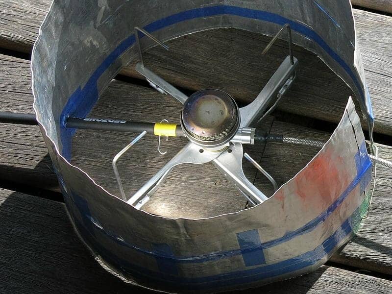
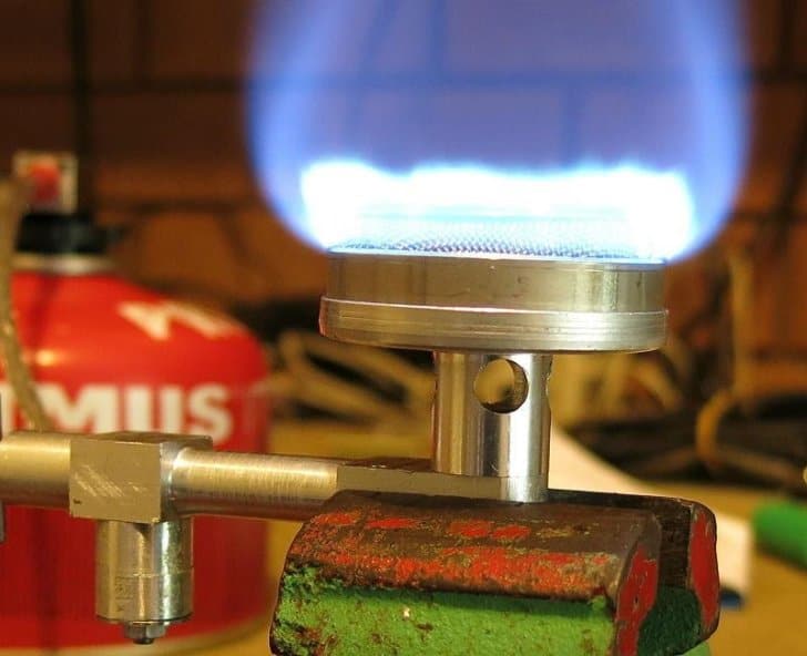
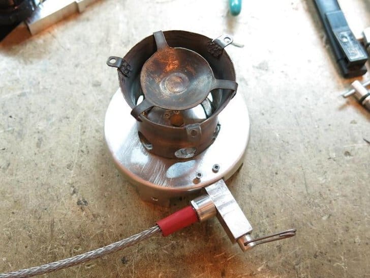
Actual development work started when I was asked to review the Brunton Stove Stand. It allowed me to put a hose onto my favourite upright canister stove (a Snow Peak GST-100). But it had a solid metal pipe where the hose connected to the body, and I wondered whether I could conduct enough heat in there to vaporise the propane/butane fuel mix as it arrived.
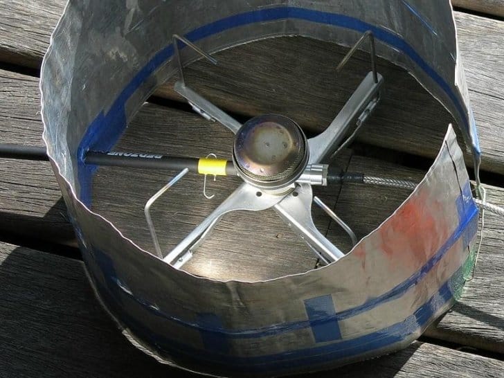
Well, no use wondering: go and do. So I did, as above (see photo), and it worked fine. There was enough heat coming down the metal strip (copper) from the flame to the pipe. After all, the pipe had only to reach something like +5 deg C. Interestingly, while a copper strip (thermal conductivity 400 W/m∙K) worked fine, a brass (61-111 W/m∙K) strip was not so good. For interest, plain aluminium is 236 W/m∙K while Ti is 22 W/m∙K. Obviously, good thermal conductivity would be needed. This metal strip is now called the Heat Shunt.
But the original steel legs on the Brunton stand were heavy, the large base was heavy, and the hose was stiff. If I did some engineering, made some lighter legs, and integrated the needle valve with the base, better was possible. And so the long journey got going.
On one trip in the Pyrenees, the brass thread (where the stove connects to a canister) on my GST-100 had been stripped by the very rough steel thread on the screw-thread canisters. I had to suddenly buy a Campingaz stove (lumpy and heavy) and Campingaz canisters (nice). I wanted to get away from that crude rough steel thread, and I had quite a few nice full Powermax canisters on the shelf. Could I make a universal canister connector?
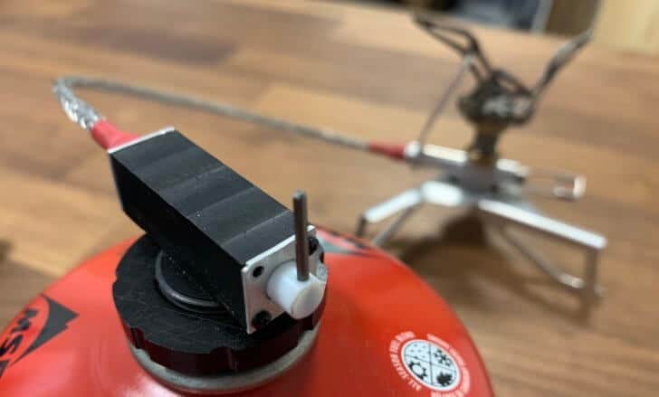
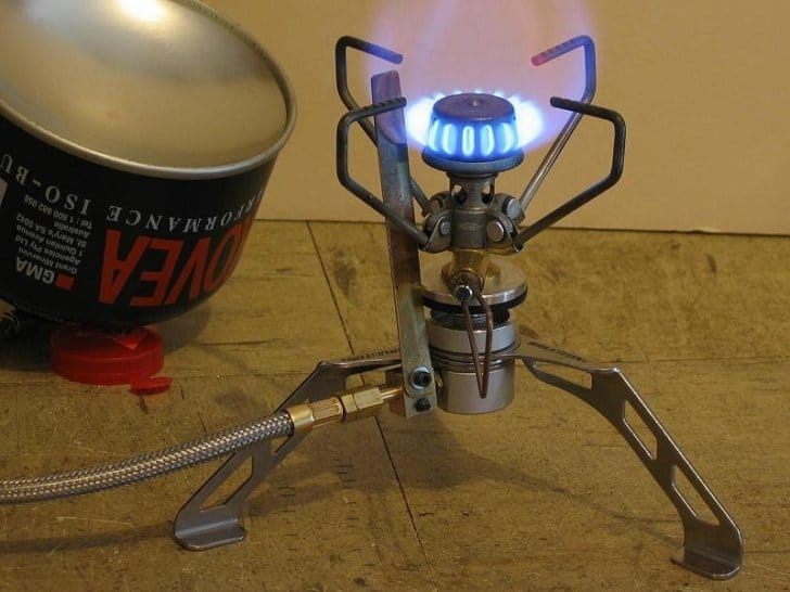
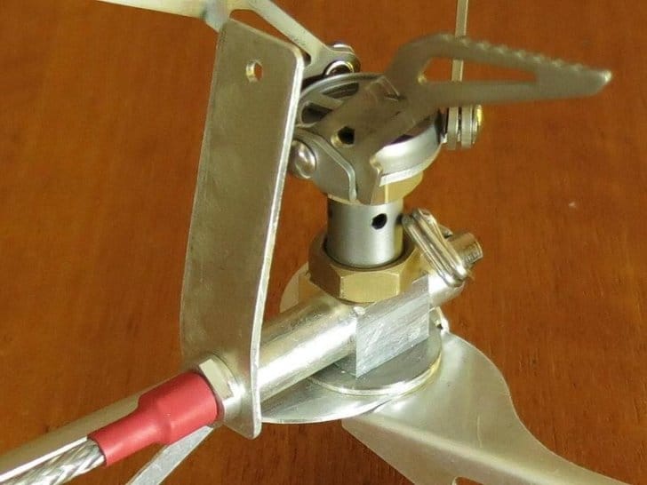
Jumping ahead several years, this is what I envisaged: compatible with screw-thread, Campingaz and Powermax, and having a fast ultra-reliable shut-off facility at the canister, separate from the control valve. It was possible, and it has been described in my previous stove articles. At the same time, I was able to make a thoroughly satisfactory but light-weight armoured hose, as seen in the above and below photos.
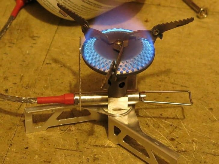
But developing the whole system had taken a year or two, and I had become a bit impatient. I decided to use a commercial burner head on my stove body and legs to get things going. I could pick a burner head which was light and effective, and it would save me a lot of work. I used two stoves for this: at first the Fire Maple FMS-116 and later on the Fire Maple FMS-300.
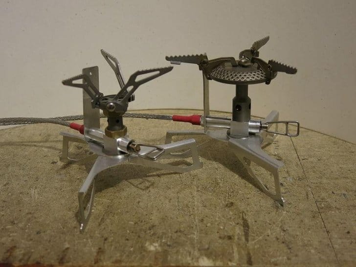
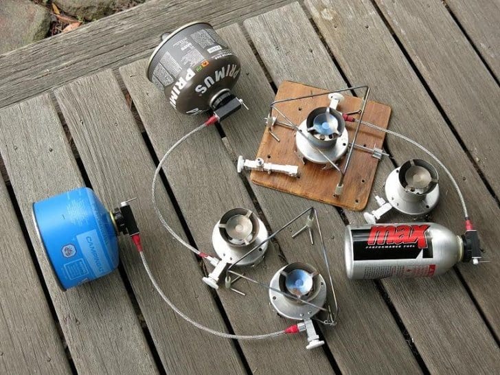
The FMS-300 had, to my mind, a better gap between the burner head and the pot, permitting better combustion and lower CO levels. Also, I cheated slightly and reused the needle valves out of the stoves. Purely as a side note, you might like to compare the Fire Maple FMS-300 (on the left) with the BRS-3000t: there is not a lot of difference, and I believe the FMS version was first. A performance comparison between the two can be found in Backpacking Light’s most recent upright canister stove gear guide.
Anyhow, my V1 stove was successful, and I sold well over 100 of them. I was very pleased, and my wife was impressed (which was not easy to do).
Despite the sales, I was not entirely happy with using a commercial burner head. I wanted to make my own burner head. So I started to experiment (and use up a lot of gas in the process).
The Vortex Diversion
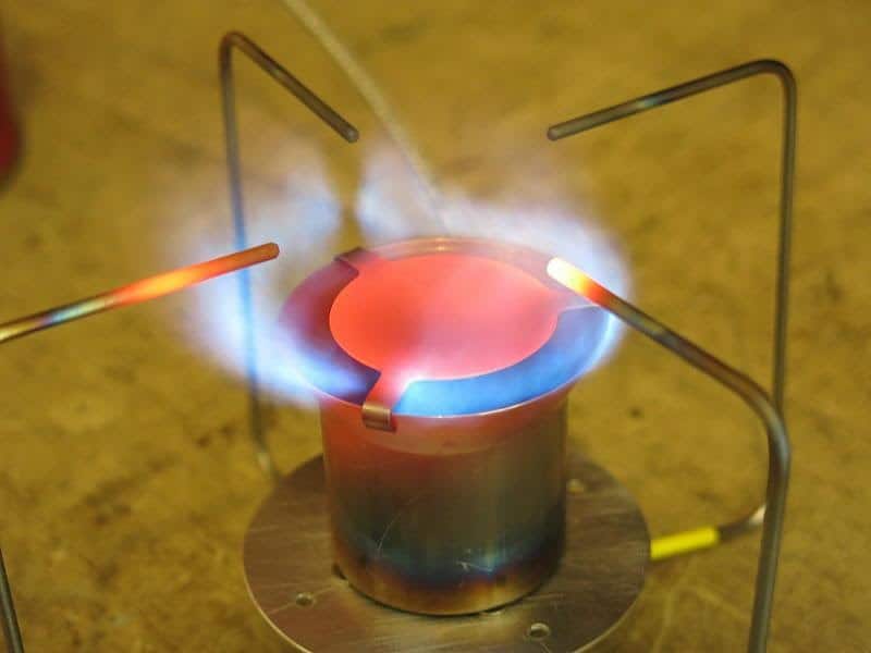
I was well on the way down this path when I suddenly started thinking about Vortex Burners: they are very different from the conventional designs above. I was hooked and spent the next few years happily playing with them – to the point of producing two slightly different models and selling them as well.
Rediscovery
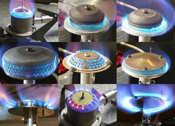
I was tidying up the workshop after making and selling my V2 and V3 stoves when I opened up one of several boxes of left-over parts. I found all the old burner heads I had been experimenting with after V1, plus about 14 (quite refined) burner heads I had been just about to fit onto stove bodies. I had forgotten all about them.
Out of interest, I examined them closely. All very nice in fact. Some were made from titanium tubing I had lying around, and others were made from machined aluminum. They were all very light, and they all made a nice broad flame.
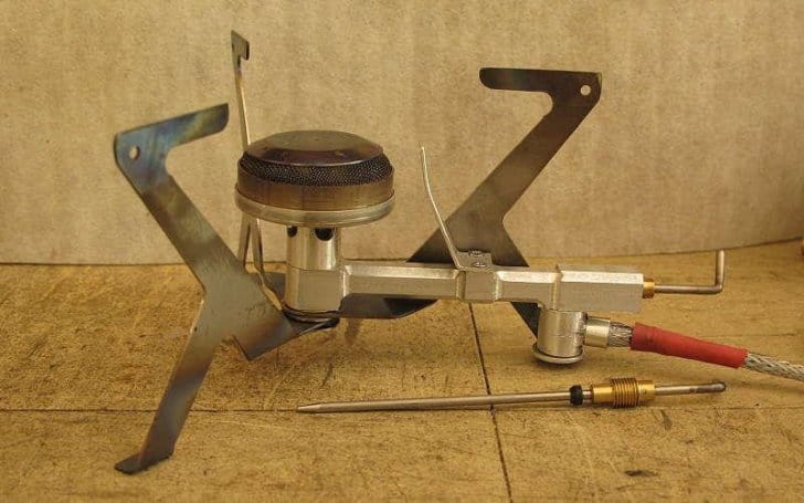
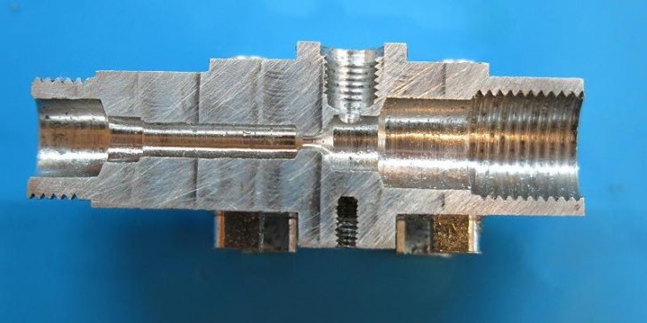
Then I looked at the stove body design that came with these heads in the left-overs box: that’s the bit held in the vise in the photo above. It’s rather long, with a pivoting connection for the hose, and I began to remember that both the length of the stove body and the pivot on the hose had both given me a lot of trouble.
The long stove body presented two problems. The needle valve is perforce directly under the jet. This means a delicate drilling operation for a precisely concentric 1 mm hole at the end of a long thin (4 mm) bore, and I could not find a suitable stock drill bit for this. I had to get some custom-made in China for it. In addition, machining a long thin aluminum needle to fit down the long bore had been difficult: the long thin aluminum rod insisted on flexing in the lathe.
I tried using some titanium rod for the needle, and this machined OK, but actual field use revealed a terminal problem when I shut the stove down after use. You see, aluminum has a significantly higher coefficient of thermal expansion than titanium. When the stove cooled down the aluminum body shrank more than the titanium needle, which meant that the needle ended up jammed hard in the orifice. It was very hard to reopen the valve. Long-term reliability? Very poor. Not good enough.
Then I looked at the pivot connection for the hose: the little bit sticking down from the long stove body, near the black O-ring on the spare needle valve. I could buy larger versions of these pivots, but not small ones. My memory was that machining these had been even more complex and slow. The problem lay in how you hold them. There had also been a small problem with the gas flow: going from the pivot connection into the side of the needle valve. There was not a lot of room at the bend for the fuel. I began to remember why I had abandoned the idea and switched to designing Vortex Burners.
But still, I wondered whether I could do better now, with the advantage of many more years of stove design. Ah, the challenge! Further optimisation of the burner head, and a much smaller and simpler stove body at least.
Stove Body
The first decision was that the revised stove body had to be very short, both to keep the weight down and to make the machining easier.
The hose connection was not difficult: I had developed a neat simple connection method for previous stoves which could be further developed.
Part of the problem with the long stove body had been having the hose connection at the same end of the stove body as the valve, even though it had ‘seemed like a good idea at the time’. If I put the hose at the other end, as in V1 as shown in the previous photo, everything fitted nicely.
A very technical point should be made here about how the gas flow goes in at the opposite end from the needle valve. Any dirt or wax from the fuel (it happens) which wants to collect somewhere will most likely blow through the needle orifice, leaving it clean, and it will then collect on the needle. It can often be cleared by movement of the needle valve, or if it’s really bad, by removing the needle valve and wiping it. The overall length of this stove body is under 40 mm, so the needle valve is very short and much easier to machine in the lathe. These factors made both the stove body and the needle valve much easier to manufacture – and lighter too.
Handle and Windscreen
While both the stove body and the needle valve are small, one does have to be able to adjust the valve while the stove is running. I soon found out that there was a fair bit of radiation that close to the stove body (rather warm fingers), so some sort of handle would be needed. The V3 stove used a long Ti wire handle, but the machining was a bit complex. Perhaps a very light bit of tubing could be made to connect somehow with the short but solid handle on the needle valve?
Carbon fibre tube is very strong and quite light, and I had a fair amount of bits and pieces leftover from making tunnel tents. It was a simple matter to make the handles on the needles fit snugly inside the CF tubing. However, the tube had to not only fit, but connect reliably so the valve could be turned reliably. Since the CF tube could be rather long, it was also necessary that it should be removable for packing.
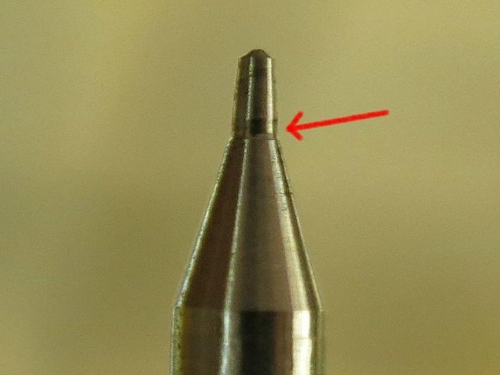
I chamfered the entry into the slot just a little so that I could simply push the CF handle over the end of the valve and spin it a bit to get the wire to drop into the slot. Should the connection ever start to get a bit loose, a tiny bit of a crimp in the wire would restore the grip. In practice, this was very effective.
Summary So Far
This article covers all the easy bits. The next article will go into some detail about the development work needed to get a design that satisfied me: optimising the burner head and coming up with a neat solution for the stove legs and the pot supports.

Discussion
Become a member to post in the forums.
Thanks @Roger,
I went and checked, and it measures 21.5cm across, so about 3.5l.
However, that doesn’t mean it is ever full of 3.5l water. I put in a bit of water, and the fill it with snow. I do add snow partway through, but never end up with it full of water.
Don’t I remember @Ryan Jordan using a ~6l popcorn pot for group trips?
I have some of the tall, narrow 2l pots, and there is no way I could get enough snow in those in any time effective manner to melt enough for even two people.
Does 21.5 cm count as a ‘large’ diameter in your experience, creating the issues of reflecting heat back down?
I would never use that on an upright canister stove, simply because of balance issues.
@Tjaard
21.5 cm – that is probably OK with a REMOTE canister stove, imho.
I hear you about snow melting. It doubles my fuel consumption.
Cheers
AHHH! A cliff hanger ending..
well done Sir
Part 2 this week I believe.
Cheers
Great article!
I want to buy one!
Let us know when you’re ready to make a small serie for us gear-lovers.
Binne Smid
Yeah, great articles, I like the sleeping on problems part…
If a stove flame output is turbulent, there may be better heat transfer leading to more efficiency
Are you considering this in your designs? Are you measuring grams of butane to boil a volume of water?
Hi Binne. Please email me direct via roger@backpackinglight.com for details.
Hi Jerry: oh yes, the flames are turbulent for sure. With the rates of expansion due to burning they could not be otherwise. There is also turbulence at a micro scale inside the burner head: that is how we get the fuel/air mixing.
As to efficiency, see for example our articles
https://backpackinglight.com/canister_stove_efficiency_p1/
https://backpackinglight.com/canister_stove_efficiency_p2/
https://backpackinglight.com/canister_stove_efficiency_p3/
and
https://backpackinglight.com/heat-exchanger-pot-test-hx-haa-caffin/
for some figures.
I don’t use ‘grams per litre’ very much myself; rather I use ‘grams per day’ for the two of us in practical conditions (ie, walking). Over long periods in the mountains (like 2 – 3 months) I find I use 30 grams per day for the two of us in summer, and I allow 60 g/day for the two of us in the snow. The latter is probably excessive, but it does allow for melting snow every day – which I try to avoid.
Cheers
Roger, thanks for sharing your stove design “secrets.”
Do you have a photo of the V4 stove folded up, with rough dimensions?
Thanks again.
Photo from David G of V4 stove inside a Toaks 900 mL pot, 115 mm diameter.

Cheers
Very cool to see! Looks like a fantastic stove!
How big is the pot support from side to the other? (In other words, what diameter pot would exactly Line up with the pot supports)?
4 pot supports, not 3.
Between inner ends of pot supports: 70 mm (beer cans need not apply)
Between Ti wire uprights: 124 mm (but note that the outer corners have a radius)
Larger pots (up to a point) are of course fine.
Cheers
Is there some info about the exchangeable gas cannister connectors in some of the other articles maybe? (I hope i haven’t missed it here…?)
I’m interested in getting one of these stoves (will send a mail!) and would like to know a little more about compatibility with different containers and their usages. I see you mention three different connectors, and the most common here in Sweden/Europe are the 7/16″ and the bayonet(?). Is there something special to think of when using different types of cannisters, with gas or liquid feeding?
Trying to get a grip on the different connections I found http://bushwalkingnsw.org.au/clubsites/FAQ/FAQ_GasStoves.htm and spent quite a long time there before I saw the authors name. :)
before I saw the authors name. :)
Chuckle.
There is some info in some of the other stove articles – but a bit scattered. I don’t think we an article focusing on connectors as such.
The French Campingaz connector is the best in my opinion: safe, long-lasting and reliable. But the French did not stir their backsides to get international sales, and lost out.
The screw-thread (7/16″) is the most common, but as one might expect, it is an abortion of a design. It’s a partial steel thread, rough surface, ‘mating’ with a soft brass thread on the stoves. The stove thread strips after a while, and yes, it happened to me.
The bayonet connection is found only (?) on butane canisters (ie not butane/propane), and is designed for what we call ‘wok stoves’. We have an article coming here at BPL about them. You can buy adapters on ebay to convert them to screw-thread.
Cheers
Become a member to post in the forums.