You are here:Home/Articles/Fuel Transfer Valves for Backpacking: Fuel Physics, Myths, Risks, and Real-World Performance
Research & Testing
Fuel Transfer Valves for Backpacking: Fuel Physics, Myths, Risks, and Real-World Performance
This article examines canister fuel transfer devices from a thermodynamics and engineering perspective, focusing on pressure-driven flow, headspace constraints, fractional distillation of LPG mixtures, and measured transfer rates. It evaluates Alpenflow, FlipFuel, and generic EN 417 adapters and outlines conservative operating practices that respect established EN 417 design safety margins.
By Ryan Jordan
Introduction
Backpackers who cook with canister stoves often accumulate a small graveyard of partially used fuel canisters. Each canister contains some unknown quantity of liquefied petroleum gas (LPG). The usual strategy is to discard the canister, make a wild guess about their fuel contents, or bring an extra canister and accept the weight penalty. Over the course of a season, this pattern produces logistical friction when it comes to fuel planning, wasted fuel, recycling hassle, and unnecessary metal in the landfill waste stream.
Fuel transfer devices aim to solve this problem by enabling users to transfer fuel between canisters. The idea is straightforward: consolidate partially used canisters at home, top off a canister before a trip, and occasionally harvest useful fuel from hiker boxes or trip partners. Devices like the Alpenflow (Alpenglow Gear), FlipFuel, and a variety of generic EN 417 adapters all work from the same basic principle, but differ in how they interface with the canister, how they control flow, and how tightly they constrain the user to safer operating practices.
This article examines that product category from a physics and engineering perspective. It addresses common myths, explains the thermodynamics that actually move fuel, describes how representative devices are built and how they behave in use, and outlines appropriate safety and testing frameworks.
Table of Contents • Note: if this is a members-only article, some sections may only be available to Premium or Unlimited Members.
Funding Disclosure:Alpenglow Gear provided financial support and product samples to underwrite the development of this report.
Editorial Independence: Backpacking Light and the author retained full editorial control over this content, including all ideation, research, experimental design, analysis and conclusions with no influence from Alpenglow Gear.
Affiliate Links: This article does not contain affiliate links.
Backpacking Light does not accept financial compensation for product placements in editorial reviews. When we accept funding to underwrite non-review technical reporting or education, we fully disclose funding sources, retain full editorial control, and develop the content without brand influence, review, or approval. We do not accept financial compensation for brand-directed (sponsored) “advertorial” content. Learn more about Backpacking Light Trust Standards.
Myths and misconceptions
There is no shortage of informal advice about fuel transfer circulating online. Some of it is partially correct, but much of it is incomplete or misleading. A science-based discussion has to start by clearing a few of these out of the way.
One persistent myth is that fuel moves from the “fuller” canister to the “emptier” one. In reality, fuel flows from higher pressure to lower pressure. Internal pressure in a canister is set primarily by temperature and the composition of the liquefied gas mixture, not by how full the canister is. A nearly empty canister that has been sitting in the sun can easily push fuel into a half-full canister that has been cooled in a snowbank.
Another misconception is that refilling is safe as long as the liquid level stays below the top of the canister. These canisters are designed with a significant vapor headspace, typically about 15 to 20% of the internal volume at room temperature. That headspace is an engineered safety margin that allows the liquid to expand if the canister warms. Overfilling reduces this margin. If an overfilled canister is then exposed to higher temperatures, internal pressure and mechanical stress can rise above the conditions assumed in the original design.
A third common belief is that all EN 417 adapters are functionally equivalent. From a purely geometric standpoint, many of them do connect two Lindal valves in roughly the same way. However, there are fundamental differences in thread quality, seal design, internal passage volume, valve control, and documentation. The Alpenflow, FlipFuel, and generic Asia-made adapters all move fuel, but they do not necessarily do it with the same degree of predictability or control.
It is also common to hear that any fuel can be moved into any canister as long as the user is careful. This is not accurate. Different canisters are sold with different propane-to-butane ratios and are optimized for specific vapor-pressure and temperature envelopes. Repeatedly topping off a standard mix canister with higher-propane winter blends (or vice-versa) alters its internal mixture over time. Filling any propane/butane mix canister with pure propane is outside the assumptions used to design the shell and the valve. Use similar mixtures for both donor and recipient canisters.
Finally, there is a myth at both extremes of the risk conversation. One camp asserts that refilling is inherently unsafe and will inevitably “make canisters explode.” The other camp treats refilling as obviously benign as long as a transfer adapter is used. In practice, refilling moves the canister outside the original EN 417 non-refillable certification, and it does increase risk. At the same time, if users respect fill limits, temperature bounds, mixture compatibility, and mechanical inspection guidelines, the incremental risk can be bounded and made intelligible instead of hand-waved.
Safety guidelines & disclaimer
This article describes techniques that are prohibited by all gas canister manufacturers. Performing these techniques will void your canister warranty and absolve the manufacturer of any liability if you cause harm or injury to yourself or others. The information in this article is provided for educational purposes only and does not constitute safety guidance or usage recommendations.
Specifically, manufacturers of gas canisters warn:
Use only in well-ventilated areas.
Keep away from flames and items that create sparks.
Do not expose to temperatures above 120 °F (49 °C).
Avoid prolonged exposure to sunlight.
Do not refill canisters.
Failure to heed these (and other) warnings can result in death, burns, or property damage.
The physics of fuel transfer
To understand how these devices work, it is important to understand what is inside a canister, how vapor pressure behaves, and what actually drives fuel movement.
When two canisters are connected with a sealed passage, and both Lindal valves are opened, fuel flows from the canister with the higher internal pressure to the one with the lower internal pressure. The direction and magnitude (rate) of that flow are influenced by gravity, mixture, and temperature.
In the common “warm donor on top, cool recipient on bottom” setup used for refilling, the donor canister is typically inverted so that its valve is immersed in liquid. In contrast, the cooler recipient is kept upright so its valve opens into the vapor space. When both valves are opened, the higher pressure (created by both gravity and vapor pressure) in the warm, inverted donor drives liquid fuel out through its valve, through the adapter, and into the recipient. Inside the recipient canister, the incoming liquid falls to the bottom, partially vaporizing until the vapor above it reaches a new equilibrium pressure at the lower temperature. At the same time, vapor from the recipient canister may flow back up through the passage into the donor canister to replace the volume of liquid that left it and to prevent a vacuum from forming.
During active transfer, the small passage between canisters is effectively filled with liquid LPG; the measured transfer rates reported in this study imply liquid velocities of order 1–10 m/s in a millimeter-scale bore. Any vapor that forms at the valve faces is swept along with this liquid. Pressure equalization between donor and recipient occurs primarily because liquid in the donor boils into its headspace as pressure falls, and incoming liquid in the recipient partially vaporizes as pressure rises, not because of a sustained counter-flow of vapor through the connector.
The details of how the passage is opened – a needle valve in a threaded device like FlipFuel or manual clamping with a press-fit device like Alpenflow – do not change the core physics: liquid flows from the higher-pressure, warmer, liquid-fed valve toward the lower-pressure, cooler canister, while vapor circulates in the opposite direction so that the pressure difference, set by temperature and evolving mixture composition, is gradually reduced.
Fuel stops flowing when the driving pressure difference disappears or when the user mechanically closes the passage. As liquid leaves the warm donor canister and evaporates at its valve, the donor cools slightly and its internal pressure drops. At the same time, the cooler recipient is gaining liquid, some of which vaporizes, warming the recipient slightly and raising its internal pressure. The temperature gradient that initially drove flow therefore shrinks over time, and so does the pressure gradient. Once the vapor pressures in the two canisters (plus any small hydrostatic difference due to elevation and liquid column height) equalize, there is no net force pushing liquid one way and vapor the other, so bulk flow essentially ceases even though the valves are still open. In practice, users usually stop the transfer earlier by breaking the clamp or closing a valve in response to their audible perception of decreasing flow rate. The underlying physical endpoint is the same: when pressures equalize, both liquid and vapor transfer rates drop to negligible levels, and the system settles into a new static equilibrium.
What drives fuel flow between two canisters at the same temperature?
Consider the simple case where the donor canister starts full of fuel, and the recipient canister starts empty and has just been vented to the atmosphere. At time zero (the point at which a fuel transfer device is actuated), the donor contains LPG with saturated vapor in the headspace above it. Therefore, its internal gas pressure is approximately equal to the fuel mixture’s saturation vapor pressure at that temperature, plus a small hydrostatic term from the liquid column above the valve. If the donor is inverted and the liquid surface is a distance h(t) above the valve, the donor pressure can be written as:
P_donor(t) ≈ P_sat(T) + ρ⋅g⋅h(t) {eq. 1}
where
P_sat(T) is the saturation vapor pressure of the LPG mixture at temperature T;
ρ is the liquid gas mixture density; and
g is the gravitational acceleration constant.
In practice, a canister that has been used in a stove until it seems “empty” still contains LPG vapor in its headspace. During normal use, gas only flows out through the Lindal valve; air is not drawn back in. For modeling the early stage of a transfer, it is reasonable to treat the recipient’s initial internal pressure as close to atmospheric, but its gas phase is predominantly low-pressure fuel vapor:
P_recip(0) ≈ P_atm {eq. 2}
When the valves are opened and the two canisters are connected, the initial driving pressure for flow is the difference between donor and recipient pressures:
In the early phase of the transfer, the term [P_sat(T) − P_atm] is much larger than the hydrostatic term ρ⋅g⋅h(0), so the process is dominated by vapor-pressure difference rather than hydrostatic head. The donor pressure is several bars, the recipient pressure is near 1 bar (atmospheric pressure), and the resulting ΔP(0) produces a strong initial flow from donor to recipient. A simple way to represent the mass flow rate (ṁ) is with an orifice model:
ṁ(t) = K⋅√[ΔP(t)] {eq. 4}
where
K is an effective conductance that lumps together valve and adapter geometry and the discharge coefficient.
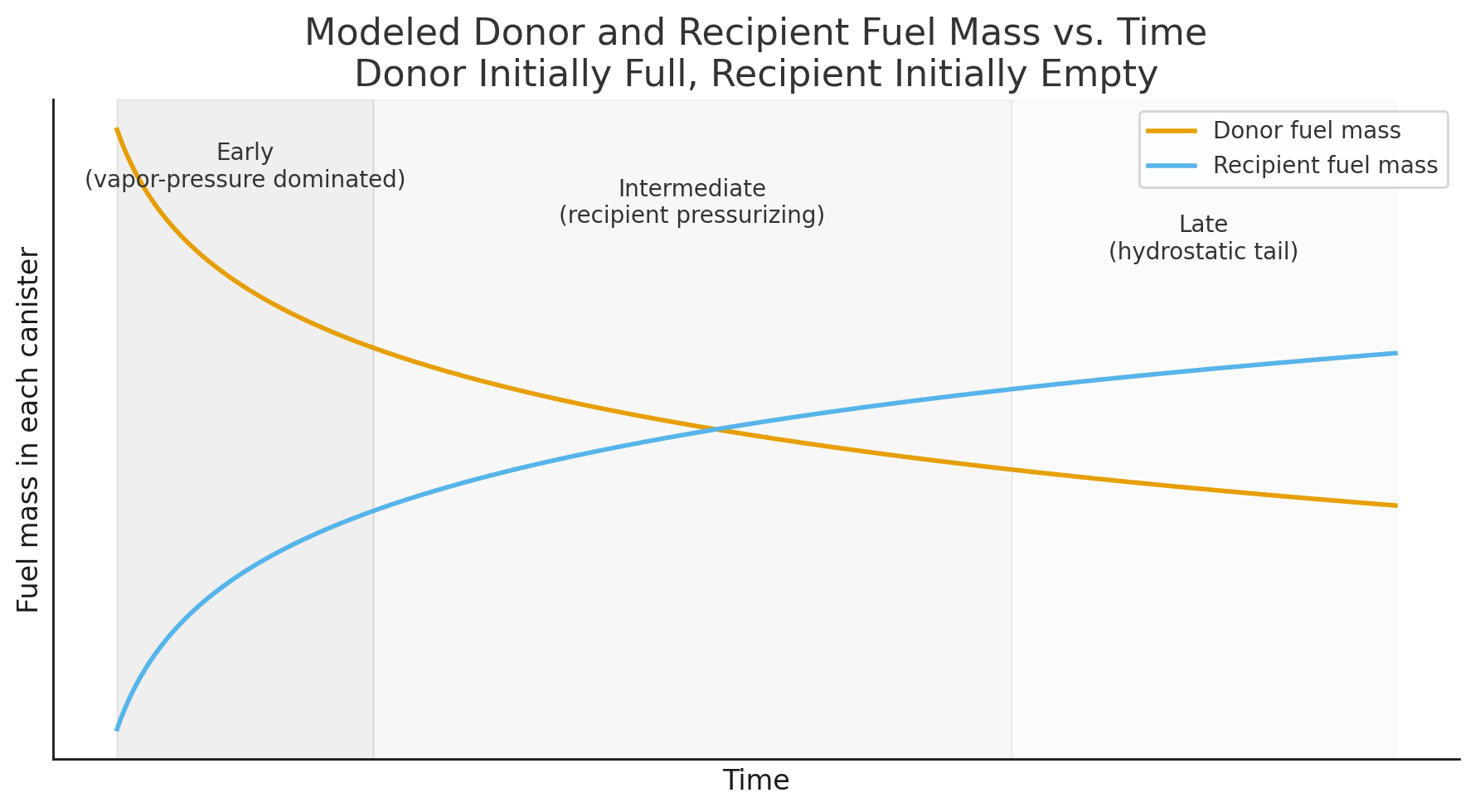
At this stage ΔP(t) is large, so ṁ(t) is large. On a mass-time plot, the donor’s fuel mass m_donor(t) decreases steeply, and the recipient’s mass m_rec(t) increases steeply (see the “Early” phase in the following plot):
Equalization of mass between two canisters (donor full, recipient empty) undergoing fuel transfer in response to a constant-temperature pressure gradient.
As LPG flows into the recipient, the system enters an intermediate phase (see the “Intermediate” phase on the graph above) where the recipient pressure continues climbing above P_atm. The recipient vapor now contains LPG > 1 atm (partial pressure grows from zero toward its own saturation pressure at the recipient temperature). A simple way to capture this behavior is to model the recipient pressure as asymptotically approaching the saturation pressure as LPG mass accumulates:
m_moved(t) is the cumulative LPG mass that has transferred into the recipient;
M_scale is a characteristic mass scale over which the recipient transitions from “monophase LPG where headspace is near 1 atm” to “dual-phase LPG where headspace P >> 1 atm” behavior.
The instantaneous driving pressure is then:
ΔP(t) = P_donor(t) − P_rec(t) {eq. 6}
Since P_rec(t) is increasing with time, ΔP(t) decreases. From equation (4), this means ṁ(t) decreases as well. On the mass-time graph, both curves begin to bend: the donor’s mass continues to decrease but with a gentler slope, and the recipient’s mass continues to increase but also with a gentler slope.
Eventually, the system reaches a late phase (see the “Late” phase on the graph above) where the recipient has accumulated enough LPG that it now contains liquid fuel with saturated vapor above it, just like the donor. If both canisters are at essentially the same temperature, their saturation pressures are approximately equal, so the gas-phase (partial pressure) contribution to canister pressure gradient largely cancels in equation (6). The donor still has liquid above its inverted valve, so a small hydrostatic head remains, and the driving pressure reduces to:
ΔP(t) ≈ ρ·g·h(t) {eq. 7}
As fuel continues to move, the liquid level in the inverted donor drops toward the valve, reducing h(t) and therefore reducing ΔP(t). As h(t) approaches zero, the hydrostatic term goes to zero, ΔP(t) approaches zero, and thus ṁ(t) approaches zero by equation (4). In the mass-time graph above, this appears as a long, shallow tail: the donor mass m_donor(t) approaches a final asymptotic value, the recipient mass m_rec(t) approaches a corresponding final value, and the transfer process naturally stops when the donor’s valve is no longer submerged and the pressure difference between canisters has effectively vanished.
Experimental validation
We have conducted more than 200 fuel transfer tests using the Alpenflow to understand its performance under various conditions. In selected tests, we monitored audio at the valve using a very low self-noise (< 10 dB-A) condenser microphone with high sensitivity (SNR > 80 dB). Matching that audio to high-frame-rate (240 fps) videography recordings gave us insight into the various fuel transfer phases and what was happening during the first few hundred milliseconds of a fuel transfer cycle. For other tests, we monitored donor/recipient canister and ambient temperatures (using standard and infrared thermography and thermocouples, canister fuel mass (using a balance with a calibrated accuracy of 0.1 g), and transfer times (to within 0.01 sec).
The primary outcome of these experiments was the calculation of fuel transfer rates under various conditions. With the Alpenflow fuel transfer device, the early phase (see graph above) occurs quickly – within about 0.1 seconds. During this phase, fuel is transferred at a rate close to the maximum liquid fuel flow rate through the device (about 10 to 15 g/s). During the transition phase between early and intermediate phases (between about 1 and 5 seconds), fuel flows at a rate of about 2 to 6 g/s. During the intermediate phase (between about 10 and 150 seconds), fuel flows at a rate of about 0.5 to 2 g/s. During the late phase (longer than 150 seconds), fuel flows at a rate of less than 0.1 g/s and is dominated by hydrostatic pressure.
The following video shows the progression of these phases during a room-temperature transfer from a donor canister that was 65% full to an empty recipient canister. At the end of this transfer (which lasted a total of about three minutes, the donor canister was about 7% full and the recipient canister was about 57% full (about 1% of the fuel was lost due to uncontrolled losses from the fuel transfer device).
Influence of fractional distillation
Most backpacking fuel canisters contain a mixture of propane, isobutane, and n-butane. At typical ambient environmental temperatures, the fuel exists in two phases. The bulk is a liquid phase at the bottom of the canister. Above it is a vapor phase that is in equilibrium with the liquid. The internal pressure is the vapor pressure of the LPG mixture at the current temperature:
P_vapor(T) ≈ Σ [ x_i · P_sat,i(T) ] {eq. 8}
where:
x_i = mole fraction of component i in the liquid; and
P_sat,i(T) = saturation pressure of pure component i at temperature T.
Propane has a higher saturation pressure than butane at a given temperature. Early in a canister’s usage life, the vapor phase is relatively rich in propane, so the canister has a higher vapor pressure and better cold-weather performance. As the canister is used, the stove preferentially boils off propane from the vapor space at the top. The remaining liquid becomes richer in butane, and the vapor pressure at a given temperature gradually decreases. Over its lifetime, the canister undergoes a mild form of “fractional distillation”: the composition of the remaining liquid shifts, and so does its pressure-temperature behavior.
This dynamic influences fuel transfer because connecting canisters with different fill histories and mixtures means that their pressure response to temperature will not be identical, and the pressure difference driving transfer will change as fuel moves.
Influence of temperature
In practice, fuel transfer rates can be enhanced by manipulating pressure gradients by creating a thermal gradient between the donor (warm) and recipient (cool) canisters. For two canisters containing equal amounts of fuel at similar fractional compositions, the vapor pressure in the higher-temperature (donor) canister will be higher than the vapor pressure in the lower-temperature (recipient) canister, driving fuel transfer from the donor to the recipient. Because temperature influences vapor pressure, large temperature gradients can drive fuel transfer even when the donor contains less fuel than the recipient, or when the donor mixture has a lower overall vapor pressure than the recipient.
Canister temperatures can be manipulated using water, sunshine, or body heat. Examples of how to manipulate canister temperatures:
Place the donor canister in a warm water bath, and/or the recipient canister in an ice water bath, refrigerator or freezer.
Place the donor canister in the sun and the recipient canister in the shade.
Place the recipient canister in a cold stream or lake, or bury it in snow.
Place the donor canister inside your jacket or sleeping bag (assuming you’re in it).
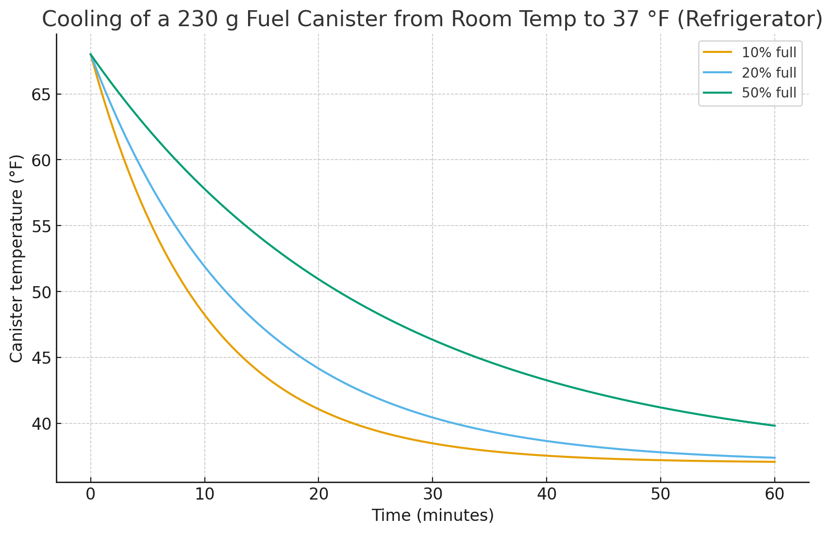
The rate at which a canister warms (or cools) will depend primarily on how much fuel is in the canister. It will take about twice as long to cool (or warm) a full canister to a set temperature as it does a half-full canister. Cooling dynamics can be visualized in the following graph:
Headspace, expansion, and overfilling
If you simply let the system run until audible hissing stops, you are allowing the two canisters to achieve a new thermodynamic equilibrium: the same vapor pressure (at their respective temperatures), with no net liquid or vapor flow. From a physics standpoint, that endpoint is not inherently dangerous. The device is just doing what a piece of tubing between two LPG vessels will always do.
The risk comes from what you aren’t controlling while you wait for that equilibrium:
You have no guarantee that the recipient canister’s final liquid mass is below its rated “full” weight (~80 to 85% of the canister volume). If the donor started full (e.g., 80% by volume of liquid fuel), the temperature gradient is large, and the recipient already contained more than 10% by volume of liquid fuel, the equilibrium state can result in a substantially overfilled recipient with inadequate headspace. That may still look and feel “normal” when the canisters are cold, but it pushes the recipient closer to its safety limits if it later warms up (e.g., if left in the sun or on an automobile dashboard).
The manufacturer’s specified net weight of fuel in a new, full canister is intended to provide adequate headspace at a reference temperature (usually near room temperature). Exceeding that net weight reduces the available headspace (vapor-phase gas) in the canister. This reduces the safety margin when the canister is exposed to higher temperatures. At higher temperatures, liquid gas expands, increasing the vapor pressure in the headspace. If that headspace vapor pressure exceeds the pressure design limit of the canister, then the canister will rupture.
Under the EN 417 Standard, canisters are type-tested so they do not leak or show permanent deformation at a “test pressure” that is at least 1.5X the maximum service pressure at 50 °C (and never less than 10 bar), and they must not leak or burst until at least 1.2X that test pressure is reached. For typical backpacking LPG mixtures, this corresponds to surviving internal pressures on the order of 300 to 350 psi without bursting.
If you were reckless enough to overfill a canister to 95%+ liquid and then heat it in very hot water (e.g., approaching the boiling point) or use an overly conductive Moulder strip with it, the combination of almost no headspace plus aggressive heating could push internal pressure up into, or even beyond, that same 300 to 350 psi range. In other words, an overfilled canister in a high-temperature environment is exactly the scenario that reduces the factor of safety that EN 417 is trying to preserve. Do not exceed the manufacturer-rated full net weight of fuel in the canister.
That said, I have performed stress testing (overfilling to 90%+ liquid capacity and then dropping into hot water > 80 °C) more than two dozen times with several brands of canisters, including Jetboil, MSR, and Optimus. No canisters ruptured, and in most cases, no leakage occurred. However, in about 30% of tests, leakage through the Lindal valve occurred, most likely due to failures of elastomeric valve components. This damage was permanent in about 50% of cases (i.e., very slow fuel leaks persisted) and may pose a substantial risk if the canister were used with an operating stove and exposed to combustion. (Do not conduct these types of tests on your own. They are dangerous and require careful safety controls, including blast shielding.)
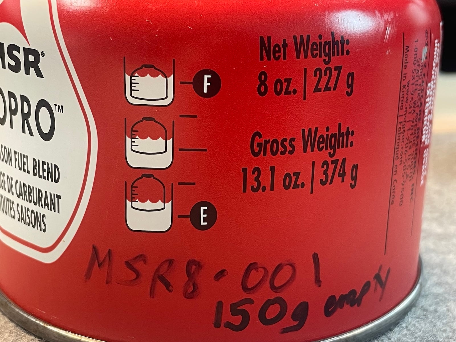
Some brands of canisters have water-immersion gauges printed on the canister so you can evaluate the approximate fuel level. If you immerse your canister in water (lake, stream, pot, etc.) and the waterline is higher than the “F” (full) line on the canister, you have exceeded the safe operating fuel capacity of the canister.
In practical terms, most of the fuel moves in the first several seconds of a transfer session, when the pressure difference is largest. As donor and recipient pressures converge, the remaining flow slows, and the last several grams of fuel may take disproportionately long to move. Letting the system run all the way until flow is essentially zero doesn’t tell you anything useful about whether you’re still below the canister’s safe fill mass; it just gives the recipient a little extra fuel that you’re no longer actively controlling. That extra “tail” of transfer is what increases the chance of quietly drifting past a safe fill level if you are not monitoring the canister’s fuel level as you go.
In addition, the valves and surrounding metal cool during sustained flow due to evaporative cooling at the orifices. At very low (e.g., winter) temperatures, cooling can promote icing around valve stems and seals, which, in turn, can affect how well the valve self-closes when you finally separate the system. That is a secondary risk compared to overfilling. Still, it is not zero, and I have observed Lindal valves persistently leaking numerous times when transferring fuel between canisters at ambient temperatures below freezing. The problem usually resolves once the canister is warmed and the ice around the valve has melted.
In summary, it’s important to realize that allowing the system to equalize pressure is not, by itself, hazardous. The practical safety issue here is that you generally do not want to sit there and “let it finish”, especially in cases where the temperature gradient is high, and the combined fuel in both donor and recipient exceeds the rated capacity of the recipient. The safest operating practice is to transfer fuel using controlled pulses of flow (5 to 10 seconds each), evaluate the fuel level, and repeat the cycle as long as the fuel level remains below the recipient canister capacity.
Fuel transfer device product landscape
The devices considered here all accomplish the same broad goal: they connect two Lindal valves and allow pressure to equalize in a controlled manner. The engineering details, however, differ significantly.
Alpenflow (Alpenglow Gear)
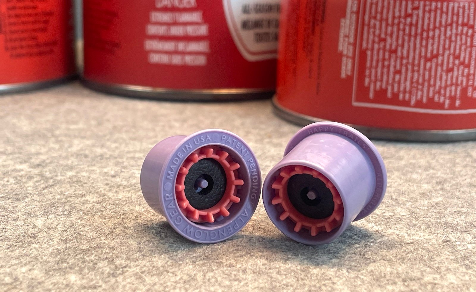
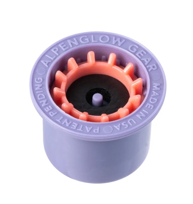
The Alpenflow is an ultralight, non-threaded transfer device that weighs roughly 2.4 grams. It is built around a micro-injection-molded polymer body with a very small internal bore and an insert that contacts the valve stems. Instead of threads, it uses a press fit geometry that mates with the recess around the Lindal valve. The user seats the Alpenflow between two canisters and presses them together so that the adapter simultaneously depresses both valve stems.
Alpenflow fuel transfer device, by Alpenglow Gear. The housing (purple) contains the Lindal valve coupling (pink). Lindal valves are actuated by a pin (purple, center) and sealed by manually compressing the canister valves against the soft, rubber-like transfer device seals (black).
Because there is no internal shutoff valve, flow is controlled entirely by the user’s clamping force and the duration of contact. When the user releases pressure, both Lindal valves self-reseal, and flow stops. The absence of threads keeps this device’s weight extremely low (since no threaded metal is required) and eliminates thread wear on the canister collar (which can compromise the seal security when attached to your stove). It also removes the possibility of leaving a device partially threaded and leaking. The trade-off is that the user must manually maintain proper alignment and pressure, which, with some practice, is not difficult. The short internal passage and small transfer device bore volume (estimated 0.1 to 0.2 ml) means that the amount of gas trapped in the device at the end of a transfer is almost negligible.
In practice, the Alpenflow is well-suited both as an at-home canister-fuel consolidation tool and as a field-carry for hikers who can pay reasonable attention to good press technique. Preserving vertical alignment with the collar is essential. During my stress-testing of the Alpenflow device, I was able to fatigue (and eventually break) one of the valve-actuation pins with excessive out-of-alignment force. Under normal use, I don’t see this as a significant user risk, just something to be aware of. I’ve done hundreds of fuel transfers with Alpenflow devices without failure when I’ve paid reasonable attention to device alignment.
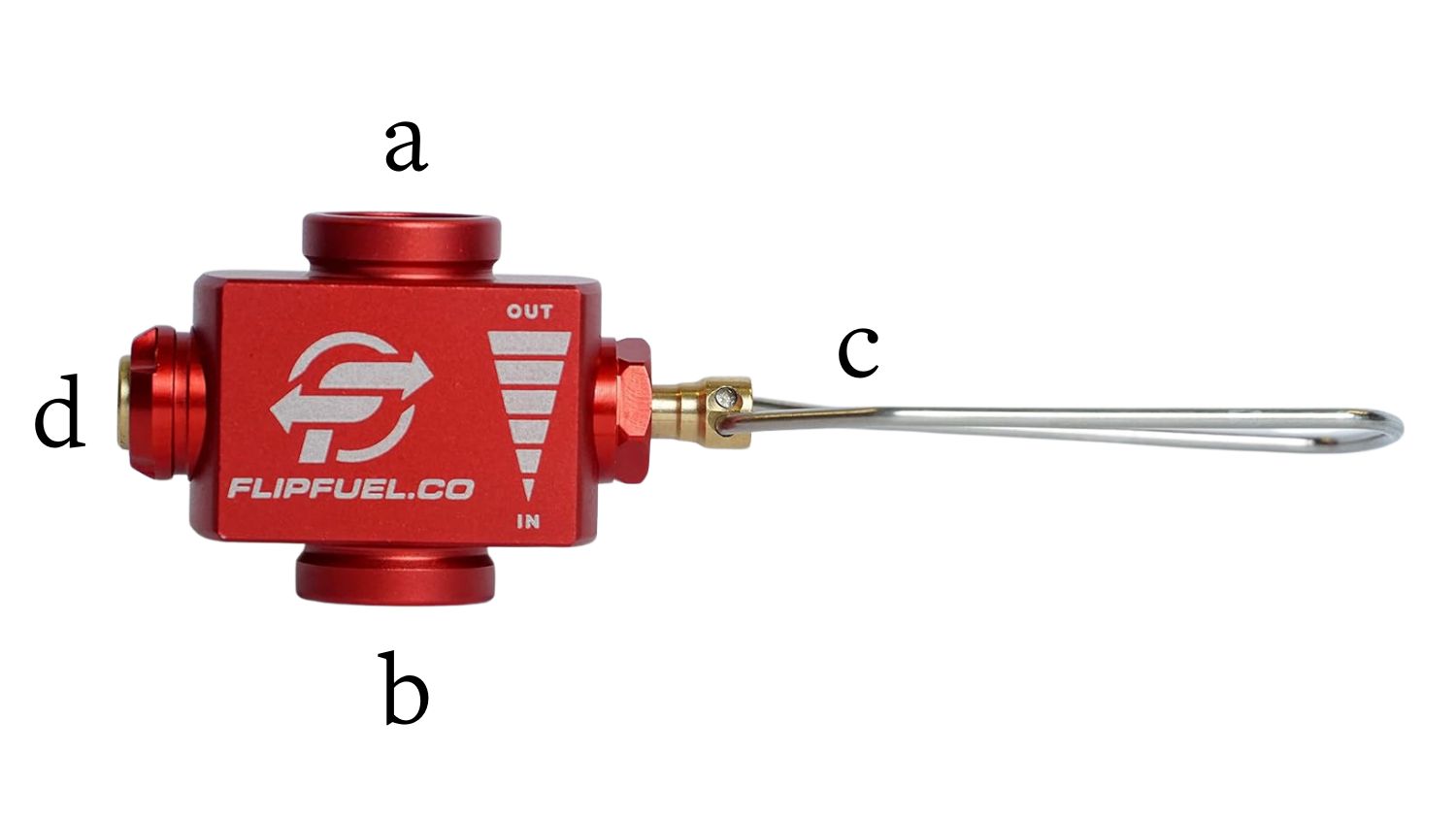
FlipFuel
FlipFuel uses a different design philosophy. It is a machined metal block with female EN 417 threads at both ends and an internal valve opened and closed by a rotating knob. Each canister is fully threaded into the device, creating a rigid assembly. Once assembled and correctly oriented, the user gradually opens the internal valve to initiate transfer.
The FlipFuel device is comprised of female (EN 417) threaded inserts for the donor (a) and recipient (b) canisters. The canister’s Lindal valves are actuated upon threading, and fuel flow in the device is controlled by a wire handle (c) that operates a needle valve inside the FlipFuel device. Because of the volume in the assembly between the two canisters, a pressure-release valve (d) should be used to vent the assembly prior to unthreading the canisters.
FlipFuel is substantially heavier than Alpenflow (about 40 grams), but it offers more control over flow. The threaded assembly can be set down during long transfers without losing alignment. Newer versions include a small vent button that allows the user to release gas trapped in the internal passage after closing the main valve. This reduces the likelihood of residual pressure releasing unexpectedly when unscrewing the canisters.
The larger body and internal cavity mean that FlipFuel traps more gas volume than Alpenflow, which increases the importance of deliberate venting. In exchange, the user gains more mechanical security and more precise control over start and stop conditions.
Generic EN 417 adapters and Asia-made knockoffs
The third category includes a wide variety of generic adapters, many manufactured in Asia and sold under multiple brand names. Most use threaded EN 417 interfaces, and some include additional ports for other canister form factors, such as nozzle-type butane cans or small propane cylinders. Internal valves range from simple needle mechanisms with little tactile feedback to more refined designs. O-ring materials and machining quality vary. We have tested several of these with varying degrees of success, with a failure/leak rate exceeding 10%.
These devices can function adequately when well-made, but there is more variability between units and more ambiguity in the documentation. Many of them emphasize cost and versatility rather than tightly defined operating procedures. Some explicitly support cross-system refilling that moves well outside the original design envelopes for backpacking canisters. As a result, using them safely requires a higher level of user knowledge and attention, and perhaps, a bit of product QA/QC luck.
Product comparison
Despite their differences, these devices are solving the same problem. The table below summarizes key technical attributes.
Feature / Spec
Alpenflow (Alpenglow Gear)
FlipFuel
Generic EN 417 Adapter (typical)
Approx. weight
~2.4 g
~40 g
20-80 g
Interface to canister
Non-threaded press fit on Lindal
7/16 28 UNEF female threads on both sides
Typically 7/16 28 UNEF threads, sometimes multi-standard
Flow control
Manual press-fit (clamping)
Internal shutoff valve and knob
Simple valves with variable control mechanisms
Internal passage volume
Very small
Moderate
Variable
Vent feature
None
Dedicated vent button (later models)
Rarely present
Compatible fuel types (intended)
EN 417 LPG mixes only
EN 417 LPG mixes only
Often EN 417 LPG, sometimes cross system
Primary design goal
Minimum weight, simple UL field tool
Controlled, secure refilling
Versatility and low cost
Typical use case
UL backpacking and hiker box consolidation
Home bench and thru hike resupply
Car camping and mixed fuel systems
Documentation quality
Very good (conservative safety guidance)
Good (moderate safety guidance)
Highly variable (poor to moderate safety guidance)
Manufacturing origin
USA
China
Primarily Asia
From a design philosophy context, Alpenflow sits at one end of the spectrum: minimum weight, minimal trapped volume, and a direct connection between user technique and fuel movement. FlipFuel occupies a middle ground, with a clear bias toward fuel control and hands-off usage. Generic adapters span a wider range and introduce more fuel transfer control uncertainty and less predictable device quality.
Summary
Fuel transfer between backpacking canisters is not magic, and it is not guesswork. It is a straightforward application of vapor pressure, hydrostatics, and basic fluid dynamics, with risk controlled primarily by four variables: temperature, LPG mixture fractions, canister headspace, and transfer device engineering. When two canisters are connected, liquid moves because a pressure gradient exists, and that gradient is controllable by manipulating canister temperatures. Most of the useful transfer happens in the first several seconds while that pressure gradient is large; the long tail of slow equalization adds relatively little fuel and a disproportionate amount of uncertainty.
For practical use, the non-negotiables are clear. If you choose to use fuel transfer devices despite manufacturer prohibitions, you should (a) treat the manufacturer’s rated full net weight as a hard upper limit, (b) manipulate temperature gradients deliberately rather than incidentally, and (c) transfer in short, controlled pulses while monitoring the fuel amount in the recipient between pulses instead of “letting it finish.” Overfilling and aggressive heating act together to reduce the safety margin built into EN 417 canister design standards. A lack of headspace and overheating are the most likely combination to cause valve damage, leaks, or, in worst cases, structural failure. In contrast, conservative fill levels, modest thermal gradients, and careful inspection of canisters and adapters keep the system within more defensible operational envelopes.
From a product perspective, Alpenflow, FlipFuel, and generic EN 417 adapters occupy different points along a design spectrum rather than competing to solve different problems. Alpenflow prioritizes minimal mass, minimal internal volume, and direct, user-mediated control, at the cost of requiring good technique. FlipFuel trades grams for threaded security and valve-based flow control, making it well-suited to bench work and long, hands-off transfers. Generic adapters emphasize cost and versatility but introduce more variability in machining quality, sealing performance, and documentation; using them safely demands a deeper understanding and more QA vigilance from the user. All three categories can move fuel effectively, but none can compensate for poor thermodynamic control or casual attitudes toward overfilling.
The data presented here – including time-resolved transfer rates, phase behavior across early, intermediate, and late stages, and sensitivity to temperature and fill fraction – support a simple conclusion. Fuel transfer devices can be used to reduce waste, consolidate partial canisters, and improve trip logistics, but only if they are treated as precision tools operating near the limits of thin-walled pressure vessels, not as convenience gadgets. If you are unwilling to monitor canister fuel capacity, track temperatures, and stay below rated fill masses, you probably should not be refilling canisters at all. If you are willing to do those things, fuel transfer devices offer a technically sound way to recover otherwise wasted fuel and avoid discarding partially used canisters.
The Alpenflow Fuel Transfer Valve addresses redistribution of fuel between partially used threaded isobutane canisters by providing a 2.4 g (0.09 oz), EN-417–compatible interface used warm-donor-top / cool-recipient-bottom with no threading, relying on a pressure differential to move liquid fuel between canisters.
Funding Disclosure:Alpenglow Gear provided financial support and product samples to underwrite the development of this report.
Editorial Independence: Backpacking Light and the author retained full editorial control over this content, including all ideation, research, experimental design, analysis and conclusions with no influence from Alpenglow Gear.
Affiliate Links: This article does not contain affiliate links.
Backpacking Light does not accept financial compensation for product placements in editorial reviews. When we accept funding to underwrite non-review technical reporting or education, we fully disclose funding sources, retain full editorial control, and develop the content without brand influence, review, or approval. We do not accept financial compensation for brand-directed (sponsored) “advertorial” content. Learn more about Backpacking Light Trust Standards.
Sponsor’s Message:
Alpenglow is the rosy light from a setting sun that reflects off peaks to better illuminate your path. Alpenglow Gear was founded by Gadget, a 2023 PCT hiker, to invent & manufacture gear that can help you along your own path as well. Each product is assembled in California after being vetted by long-distance hikers on each of America’s Triple Crown trails. The gear might be considered a luxury, but it’s never weighed less!
2025/12/08 – (1 of 2) The original article contained the statement: “The recipient canister, immediately after venting and sealing, contains only air at roughly atmospheric pressure (P_atm), so its initial pressure is.” This factually incorrect statement was corrected in an earlier edit of this article but that edit didn’t make it into this draft – thank you to David Thomas for catching this. The revised paragraph now reads: “In practice, a canister that has been used in a stove until it seems “empty” still contains LPG vapor in its headspace. During normal use, gas only flows out through the Lindal valve; air is not drawn back in. For modeling the early stage of a transfer, it is reasonable to treat the recipient’s initial internal pressure as close to atmospheric, but its gas phase is predominantly low-pressure fuel vapor…” (2 of 2) In addition, Roger Caffin pointed out that vapor flowing upward into the donor canister may be “a bit of a myth”. This is especially true during the early and intermediate stages of fuel transfer. This clarification was added: “During active transfer, the small passage between canisters is effectively filled with liquid LPG; the measured transfer rates reported in this study imply liquid velocities of order 1–10 m/s in a millimeter-scale bore. Any vapor that forms at the valve faces is swept along with this liquid. Pressure equalization between donor and recipient occurs primarily because liquid in the donor boils into its headspace as pressure falls, and incoming liquid in the recipient partially vaporizes as pressure rises, not because of a sustained counter-flow of vapor through the connector.”
Ryan Jordan is the founder and publisher of Backpacking Light. Ryan has spent more than 35 years in the outdoor industry as a guide, educator, university researcher, journalist, and publisher. His engineering background (Ph.D., Montana State University), expedition, and multisport experience inform his investigative approach to gear design and performance in response to adversarial conditions in all seasons.
Free Handbook
Get ultralight backpacking skills, gear info, philosophy, news, and more.
This article examines canister fuel transfer devices from a thermodynamics and engineering perspective, focusing on pressure-driven flow, headspace constraints, fractional distillation of LPG mixtures, and measured transfer rates. It evaluates Alpenflow, FlipFuel, and generic EN 417 adapters and outlines conservative operating practices that respect established EN 417 design safety margins.
I wish I’d seen the AlpenFlow before I grabbed a FlipFuel. The AlpenFlow has a major advantage in that you can pop the receiver canister onto a scale very quickly to check the fill level and then pop the sender canister back on if needed.
It’s great to put all this info in one place and to promote best practices when we’re playing with things that can go boom.
I’ll print out the article and review it carefully at 35,000 feet this weekend.
I thought I could just post a quick correction to the thought that there is (could possibly be) liquid going down and vapor going up at the same time, but then I got to two instances of “The recipient canister, immediately after venting and sealing, contains only air at roughly atmospheric pressure”.
Nope, nope, noppity, nope. 1) a functionally empty canister still has fuel vapor inside of it. 2) It has to because there was no driving force through the (depressed) Lindel valve between the atmospheric pressure fuel vapor still inside and the atmospheric-pressure air outside. and 3) if there was air filling the canister, you’d not be able to refill it very completely because once the receiving canister has taken half its volume of liquid fuel, the air would be compressed 2-fold (and there’d be fuel vapor pressure as well). You’d need to vent/burn most of that air-fuel mixture in the headspace and then top off the canister with more liquid fuel.
And I’m only 1/4 of the way through the article and need to get back to work when my stupid OS completes updating, so poke me in a week if I haven’t gotten back to this by then.
The recipient canister, immediately after venting and sealing, contains only air at roughly atmospheric pressure
I agree with DT: this utterly WRONG. In most cases the canister will still contain fuel vapour.
Air in an ’empty’ fuel canister being refilled? VERY dangerous. That means mixing high pressure oxygen with propane vapour. Could be interesting, if viewed from about 50 m away.
The idea that fuel vapour will go up the (generally) very small passage in the connector from the recipient to the donor is a bit of a myth. The small passage will be full of liquid fuel. The chances of bubbles of vapour pushing past this capillary flow of liquid to any meaningful extent is very minimal.
The chance of gravity driving the flow downwards is small. Oh, it might do so briefly, but the gravity force is very small. You may safely ignore it. What does drive the flow is temperature difference, and only temperature. Put the receiver in the freezer for 10 minutes and the donor in the sun, then connect the two (OUTDOORS!). When the receiver warms up and the donor cools down, disconnect and repeat. BUT weigh the receiver frequently, and (as DT warns) NEVER fill beyond the original nominal weight. There MUST be clearance above the liquid fuel in the receiver at ALL times. Indeed, if you find you have over-filled, vent the excess (outdoors) to get down to the nominal canister weight.
Finally, there seems to be another myth that walkers have these huge piles of half-empty canisters at home. Why? Surely one could simply use the old canister until the flame dies, and then replace it with a new one? When you get home with what seems to be an empty canister, take it OUTSIDE, sit it down on something solid, stick a solid nail in the valve, and hit the nail with a hammer, to break the guts of the valve. Hear it rattle inside. Then leave it outside to sort itself out. That would incidentally be safer all around.
Refilling can be done if you follow all the rules — ALL the rules. But compare the cost of a canister with the cost of fuel for your car: is it worth while?
It’s important to exercise proper skepticism about technical information one finds on the internet, unless one has firsthand knowledge of the scientific credentials of the person providing that information. Especially when safety is at stake. When safety information is written and published in reliable sources, it is drafted by highly trained and credentialed experts, and then reviewed by other independent experts, prior to publication.
It’s important to exercise proper skepticism about technical information one finds on the internet, unless one has firsthand knowledge of the scientific credentials of the person providing that information.
Chuckle.
May I paraphrase?
It’s important to exercise skepticism about any information one finds on the internet.
My one pound refillable bottles have a separate release valve. Perhaps more of a hiss than a boom when canisters fail. Unless I’m missing the stories, anecdotal evidence isn’t supporting the skepticism. Not yet anyway. I don’t hear of old propane catching fire either, but I’ve seen it.
It’s important to exercise skepticism about any information one finds on the internet.
Maybe yes. Maybe no. Skepticism in itself deserves skepticism. I’m still in the undecided category. I’d rather not explain how the fire started. I don’t feel like it’s that important to use or to promote. Those that don’t err on the side of caution should maybe stay away from the tinder.
Chuckle.
May I paraphrase?
It’s important to exercise skepticism about any information one finds on the internet.
Skepticism is appropriate, but I wouldn’t want to suggest that all information on the internet has the same level of (un)reliability. One can find thoroughly vetted, peer-reviewed information on the internet as well.
Part of the problem we are having in the US currently (e.g. with regards to the safety of vaccines and other medications) is directly related to people’s inability to distinguish between real and fake science. So let’s not sweep everything under the bus … that is how it started.
But yes … if you’re referring to social media posts, I agree.
A major youtube backpacking influencer promoted a type of plastic for cooking that wasn’t rated for boiling water, and refused to retract it or even engage when it was pointed out
Another typically sound youtuber recently posted dangerous and false info regarding bear safety. To his credit he at least engaged in the conversation unlike the first, but unfortunately didn’t change anything either
When a financial incentive is attached, be especially cautious as saving face seems to prevail over the safety of the audience
Yeah, the air remaining in the canister is butane gas.
I wonder how they fill canisters? When there is nitrogen and oxygen and other gases in the canister.
When you fill a canister that has butane gas, that has to condense into the liquid. You wouldn’t have to vent it.
When I refill, I’ll put as much as 8 ounces into it. Maybe there’s another volume of headroom that would hold another 2 ounces of liquid butane.
So, the initial volume of butane gas would be compressed 5X. 5 atmospheres of pressure.
I don’t think there is 5 atmospheres of pressure when I refill, so some of that must condense into the liquid.
When they fill the canister they must vent that air?
When they refill my large propane tanks, there’s a bleed valve they open. As they pump propane into the tank, gaseous propane vents. When it’s full (with just the right amount of headroom) liquid propane starts coming out so they turn off the pump. That’s how they avoid overfilling.
If you put butane into a canister with oxygen in it, I don’t think it would be a problem, no ignition. Just don’t put a spark in there. Don’t light your cig there :)
I wonder if nitrogen/oxygen in the head space would affect the physics of performance in the cold?
I wonder how they fill canisters? When there is nitrogen and oxygen and other gases in the canister.
Think of a very simple method.
Like maybe cooling it all down to -30 C, where the standard butane/propane mix is liquid and stays liquid.
Then take a canister withOUT the Lindal valve, pour a controlled amount of liquid fuel into it, then add Lindal valve and crimp it on. Extract canister from chamber and package.
What happens to the small volume of air that was in the canister? It probably gets flushed out with butane vapour first. Cool the exhaust gas to -5 C and collect the liquified butane for recycling. Let the rest, which is air, vent off 0 ah, through a rather high tower maybe.
I am not saying this is the only way to do it, but when you are making several thousand canisters per day (or more), it does seem simple and fast. Much faster than trying to get the fuel in through the Lindal valve!
David – good catch on the “air” comment in the empty canister, that was a missed edit on our part. The correction disappeared in a late draft during a document merge from our two peer reviewers. This has been corrected.
Roger – you’re right – vapor making its way back up into the donor canister isn’t going to happen in the early/mid stages of a transfer when liquid fuel velocity is spurting downward at several m/s. I’ve clarified this in the text as well.
These two corrections have been documented in the Updates/Corrections log at the end of the article as well. Thank you both for pointing them out.
And, just to emphasize the point in case it wasn’t obvious from the text – hydrostatic head isn’t going to have a meaningful effect until very late stages of a fuel transfer “run”.
Speaking as a practicing chemical engineer, and very familiar with the physical and thermodynamic processes involved, although I don’t agree with every single last word in the article (or in the comments), it is very well written. It covers the bases quite well.
For me, a cardinal rule is to weigh the canister when purchased, when it is full. Write the weight on the underside of the canister with a permanent marker. And never, ever fill above that weight. Different fuel mixtures may have slightly different densities, but they are all within the margin of error of the weight you measure. It is not just possible to create a very high pressure in the vapor space of an overfilled canister, if it warms up enough and it has been filled too much with liquid, the liquid can “go solid” (no vapor space) inside the canister. Warming beyond that point results in a catastrophic failure due to the expansion of liquid, which is basically incompressible. I have seen that happen with overfilled ammonia cylinders at a previous place of employment. They were left out in the sun in the Las Vegas area after being overfilled.
One myth that needs to be debunked is something I’ve seen in several so-called expert YT channels. They speak of needing to vent air from the canister during the filling process. They then demonstrate by venting fuel. There is no air in the canister. All they are doing is cooling the recipient canister by venting (vaporizing) fuel. That allows them to continue filling the receptor canister. All they are doing then is replacing what they have just vented.
” I have seen that happen with overfilled ammonia cylinders at a previous place of employment. They were left out in the sun in the Las Vegas area after being overfilled.”
video needed : )
I like to write the weight of the empty canister on it. Which you can get by subtracting the capacity from the starting weight.
I use 1 ounce per day so I put in 1 ounce for each day plus one extra ounce for margin.
Same difference though – you want to never put in more weight than when it was full.
This feature requires an active Backpacking Light Membership.
Premium Articles
You're currently viewing a free preview of a member exclusive premium article. Our premium articles include in depth journalism and insights from the Backpacking Light editorial team.
Get full article access by subscribing to a Premium or Unlimited Backpacking Light membership!


Discussion
Become a member to post in the forums.
Companion forum thread to: Fuel Transfer Valves for Backpacking: Fuel Physics, Myths, Risks, and Real-World Performance
This article examines canister fuel transfer devices from a thermodynamics and engineering perspective, focusing on pressure-driven flow, headspace constraints, fractional distillation of LPG mixtures, and measured transfer rates. It evaluates Alpenflow, FlipFuel, and generic EN 417 adapters and outlines conservative operating practices that respect established EN 417 design safety margins.
I wish I’d seen the AlpenFlow before I grabbed a FlipFuel. The AlpenFlow has a major advantage in that you can pop the receiver canister onto a scale very quickly to check the fill level and then pop the sender canister back on if needed.
It’s great to put all this info in one place and to promote best practices when we’re playing with things that can go boom.
I’ll print out the article and review it carefully at 35,000 feet this weekend.
I thought I could just post a quick correction to the thought that there is (could possibly be) liquid going down and vapor going up at the same time, but then I got to two instances of “The recipient canister, immediately after venting and sealing, contains only air at roughly atmospheric pressure”.
Nope, nope, noppity, nope. 1) a functionally empty canister still has fuel vapor inside of it. 2) It has to because there was no driving force through the (depressed) Lindel valve between the atmospheric pressure fuel vapor still inside and the atmospheric-pressure air outside. and 3) if there was air filling the canister, you’d not be able to refill it very completely because once the receiving canister has taken half its volume of liquid fuel, the air would be compressed 2-fold (and there’d be fuel vapor pressure as well). You’d need to vent/burn most of that air-fuel mixture in the headspace and then top off the canister with more liquid fuel.
And I’m only 1/4 of the way through the article and need to get back to work when my stupid OS completes updating, so poke me in a week if I haven’t gotten back to this by then.
The recipient canister, immediately after venting and sealing, contains only air at roughly atmospheric pressure
I agree with DT: this utterly WRONG. In most cases the canister will still contain fuel vapour.
Air in an ’empty’ fuel canister being refilled? VERY dangerous. That means mixing high pressure oxygen with propane vapour. Could be interesting, if viewed from about 50 m away.
The idea that fuel vapour will go up the (generally) very small passage in the connector from the recipient to the donor is a bit of a myth. The small passage will be full of liquid fuel. The chances of bubbles of vapour pushing past this capillary flow of liquid to any meaningful extent is very minimal.
The chance of gravity driving the flow downwards is small. Oh, it might do so briefly, but the gravity force is very small. You may safely ignore it. What does drive the flow is temperature difference, and only temperature. Put the receiver in the freezer for 10 minutes and the donor in the sun, then connect the two (OUTDOORS!). When the receiver warms up and the donor cools down, disconnect and repeat. BUT weigh the receiver frequently, and (as DT warns) NEVER fill beyond the original nominal weight. There MUST be clearance above the liquid fuel in the receiver at ALL times. Indeed, if you find you have over-filled, vent the excess (outdoors) to get down to the nominal canister weight.
Finally, there seems to be another myth that walkers have these huge piles of half-empty canisters at home. Why? Surely one could simply use the old canister until the flame dies, and then replace it with a new one? When you get home with what seems to be an empty canister, take it OUTSIDE, sit it down on something solid, stick a solid nail in the valve, and hit the nail with a hammer, to break the guts of the valve. Hear it rattle inside. Then leave it outside to sort itself out. That would incidentally be safer all around.
Refilling can be done if you follow all the rules — ALL the rules. But compare the cost of a canister with the cost of fuel for your car: is it worth while?
Cheers
It’s important to exercise proper skepticism about technical information one finds on the internet, unless one has firsthand knowledge of the scientific credentials of the person providing that information. Especially when safety is at stake. When safety information is written and published in reliable sources, it is drafted by highly trained and credentialed experts, and then reviewed by other independent experts, prior to publication.
It’s important to exercise proper skepticism about technical information one finds on the internet, unless one has firsthand knowledge of the scientific credentials of the person providing that information.
Chuckle.
May I paraphrase?
It’s important to exercise skepticism about any information one finds on the internet.
Cheers
It seems like this article should have been vetted prior to publication.
My one pound refillable bottles have a separate release valve. Perhaps more of a hiss than a boom when canisters fail. Unless I’m missing the stories, anecdotal evidence isn’t supporting the skepticism. Not yet anyway. I don’t hear of old propane catching fire either, but I’ve seen it.
Maybe yes. Maybe no. Skepticism in itself deserves skepticism. I’m still in the undecided category. I’d rather not explain how the fire started. I don’t feel like it’s that important to use or to promote. Those that don’t err on the side of caution should maybe stay away from the tinder.
Skepticism is appropriate, but I wouldn’t want to suggest that all information on the internet has the same level of (un)reliability. One can find thoroughly vetted, peer-reviewed information on the internet as well.
Part of the problem we are having in the US currently (e.g. with regards to the safety of vaccines and other medications) is directly related to people’s inability to distinguish between real and fake science. So let’s not sweep everything under the bus … that is how it started.
But yes … if you’re referring to social media posts, I agree.
A major youtube backpacking influencer promoted a type of plastic for cooking that wasn’t rated for boiling water, and refused to retract it or even engage when it was pointed out
Another typically sound youtuber recently posted dangerous and false info regarding bear safety. To his credit he at least engaged in the conversation unlike the first, but unfortunately didn’t change anything either
When a financial incentive is attached, be especially cautious as saving face seems to prevail over the safety of the audience
Yeah, the air remaining in the canister is butane gas.
I wonder how they fill canisters? When there is nitrogen and oxygen and other gases in the canister.
When you fill a canister that has butane gas, that has to condense into the liquid. You wouldn’t have to vent it.
When I refill, I’ll put as much as 8 ounces into it. Maybe there’s another volume of headroom that would hold another 2 ounces of liquid butane.
So, the initial volume of butane gas would be compressed 5X. 5 atmospheres of pressure.
I don’t think there is 5 atmospheres of pressure when I refill, so some of that must condense into the liquid.
When they fill the canister they must vent that air?
When they refill my large propane tanks, there’s a bleed valve they open. As they pump propane into the tank, gaseous propane vents. When it’s full (with just the right amount of headroom) liquid propane starts coming out so they turn off the pump. That’s how they avoid overfilling.
If you put butane into a canister with oxygen in it, I don’t think it would be a problem, no ignition. Just don’t put a spark in there. Don’t light your cig there :)
I wonder if nitrogen/oxygen in the head space would affect the physics of performance in the cold?
I wonder how they fill canisters? When there is nitrogen and oxygen and other gases in the canister.
Think of a very simple method.
Like maybe cooling it all down to -30 C, where the standard butane/propane mix is liquid and stays liquid.
Then take a canister withOUT the Lindal valve, pour a controlled amount of liquid fuel into it, then add Lindal valve and crimp it on. Extract canister from chamber and package.
What happens to the small volume of air that was in the canister? It probably gets flushed out with butane vapour first. Cool the exhaust gas to -5 C and collect the liquified butane for recycling. Let the rest, which is air, vent off 0 ah, through a rather high tower maybe.
I am not saying this is the only way to do it, but when you are making several thousand canisters per day (or more), it does seem simple and fast. Much faster than trying to get the fuel in through the Lindal valve!
Cheers
“It is difficult to get a man to understand something, when his salary depends on his not understanding it.”
― Upton Sinclair. From “I, Candidate for Governor, and How I Got Licked,” published in 1935.
Universal truth and all that.
Update:
“It is difficult to get a man to understand something, when his SHARES depends on his not understanding it.”
Cheers
David and Roger, thank you very much for your insights. Happy Holidays!
David – good catch on the “air” comment in the empty canister, that was a missed edit on our part. The correction disappeared in a late draft during a document merge from our two peer reviewers. This has been corrected.
Roger – you’re right – vapor making its way back up into the donor canister isn’t going to happen in the early/mid stages of a transfer when liquid fuel velocity is spurting downward at several m/s. I’ve clarified this in the text as well.
These two corrections have been documented in the Updates/Corrections log at the end of the article as well. Thank you both for pointing them out.
And, just to emphasize the point in case it wasn’t obvious from the text – hydrostatic head isn’t going to have a meaningful effect until very late stages of a fuel transfer “run”.
Speaking as a practicing chemical engineer, and very familiar with the physical and thermodynamic processes involved, although I don’t agree with every single last word in the article (or in the comments), it is very well written. It covers the bases quite well.
For me, a cardinal rule is to weigh the canister when purchased, when it is full. Write the weight on the underside of the canister with a permanent marker. And never, ever fill above that weight. Different fuel mixtures may have slightly different densities, but they are all within the margin of error of the weight you measure. It is not just possible to create a very high pressure in the vapor space of an overfilled canister, if it warms up enough and it has been filled too much with liquid, the liquid can “go solid” (no vapor space) inside the canister. Warming beyond that point results in a catastrophic failure due to the expansion of liquid, which is basically incompressible. I have seen that happen with overfilled ammonia cylinders at a previous place of employment. They were left out in the sun in the Las Vegas area after being overfilled.
One myth that needs to be debunked is something I’ve seen in several so-called expert YT channels. They speak of needing to vent air from the canister during the filling process. They then demonstrate by venting fuel. There is no air in the canister. All they are doing is cooling the recipient canister by venting (vaporizing) fuel. That allows them to continue filling the receptor canister. All they are doing then is replacing what they have just vented.
” I have seen that happen with overfilled ammonia cylinders at a previous place of employment. They were left out in the sun in the Las Vegas area after being overfilled.”
video needed : )
I like to write the weight of the empty canister on it. Which you can get by subtracting the capacity from the starting weight.
I use 1 ounce per day so I put in 1 ounce for each day plus one extra ounce for margin.
Same difference though – you want to never put in more weight than when it was full.
Become a member to post in the forums.