Forgive me for asking what may already be posted somewhere, but I’m getting a lot of errors when searching topics, lately: is there any reliable way to calculate how much air intake a windscreen needs to allow in order to keep a gas stove running without either 1) choking it, or 2) allowing too much wind to get through? I’m working on a windscreen for a stove and I realized that the first template I developed has a LOT of open space for wind to creep underneath, so I’m working to cut that space down a bit…but I don’t want to go too far. Can I look up BTUs and work from there, or what?
Topic
Windscreen airflow calculation?
Become a member to post in the forums.
- This topic has 97 replies, 8 voices, and was last updated 4 years, 8 months ago by
 .
.
What would be nice is if someone could do the chemical analysis. Air (oxygen required), fuel composition (gas components) and temperature. Then one could estimate the mass flow rate. (beyond my skill sets). It seems intuitive that the output ports must be a larger area than the input ports just due to temperature alone.
One thing that I have done in the past to help visualize the airflow is to use incense as a punk stick. You can follow the smoke trails to see how fast the air is entering and exiting ports. You can also get a similar idea by hold a lit BIC lighter up the ports. That gives you slightly different information though. My 2 cents.
Incense: that’s a very good idea, Jon. It would be a bit crude, but I might be able to approximate and experiment with some inexpensive aluminum flashing before I futz around with the Ti ribbon and screw it up. It’s my first time working with 15-3-3-3, so hopefully I won’t screw things up too badly.
Now that I think of it, I’m pretty sure that I have the instruction/spec manual for the stove; I might be able to find some information there that could be helpful.
Look at the rolls of valley flashing (aka Handyman’s Coil) in the roofing materials at Home Depot. Easy and cheap to make mock-ups before you commit your titanium foil to the tin snips.
BTW, I have found that the inlet and outlet response are coupled: increase the inlet area can really change the outlet flow.
Yeah, I got a really good price on some titanium on eBay that was the exact width I need, so that helps me with the upper edge of the screen: the lower edge with the open area for air intake is what’ll take some engineering, trial, and error. I think I’m going to try punching holes – it’s .005″ stock – and if that doesn’t work I’ll find my step drills and give those a shot. I know they’ll drill thin aluminum/flashing, but I haven’t tried to drill .005″ titanium stock before. Luckily I have a lot of scrap fiberboard laying around for a backer. The big problem is the feed line for the canister: it’s almost 1.5″ above the base of the stove legs, so I have to either slice out a slot somewhere on the body of the screen, or attempt to make some sort of provision for it where the two ends of the screen meet each other. Neither is optimal; I think I’m going to go through a lot of practice flashing.
Punching 0.005” Ti with a brand new hole puncher tends to work fine for several holes, but it will get dull (good thing they are cheap). Uninitiated? I have not had great luck getting a clean hole with no burrs. If you have holes too close to an edge, the material can crinkle. One trick is to punch in from the edge and trim after. You can add a gas line slot by punching the hole at the terminus and using a razor blade to score the slot. The material can then be removed with a needle nose pliers. My 2 cents.
Trying to punch holes in 5 thou Ti foil will lead to disaster – as already mentioned.
Trying to drill holes in the same will also lead to disaster: drill bits are not designed for very thin material.
What you can do is to take TWO bits of 1 mm or thicker fairly hard Al sheet or galvo sheet and sandwich the Ti foil (ie both sides), clamping HARD right next to where you want the hole. What you are trying to do is to keep the foil flat and prevent it from slipping. Then you use a new, good, sharp drill bit to drill through the lot. Good Luck. Drill gently.
Don’t try to reuse the holes in the Al sheet for a second drilling: that does not work. Use another area.
Similar problems apply to Al foil, brass foil, etc.
Cheers
PS: I gave up trying to use Ti foil for windshields: too springy and too much like hard work. I use the Al sheet from Trail Designs.
Hopefully I will only have to punch holes for the radii of the inside corners of my cuts, but I thought about doing exactly as you say, Jon, and slotting the gas line access. Thanks for the tip on the pliers; that’s a good solution to that narrow piece of metal that must be removed.
Roger: if galvanized metal works just as well as aluminum, can I just use scrap sheet steel as well? I may well have some light-gauge pieces of that laying around; I see no reason that it wouldn’t be analogous to the other materials you mentioned. If the purpose is keeping the foil from slipping/moving/deforming, pretty much any hard, thin metal sheet would work, yes?
So, question: does this hole look clean enough?
I decided to see how bad the wrinkling/deforming/catastrophe issue would be on a scrap piece that I cut with scissors (which worked pretty well). So I picked a 1/4″ Forstner bit, held the foil down on a piece of 1/8″ fiberboard, and punched a hole through it with the drill press on 300 RPM. Took about three seconds.
Acceptable?
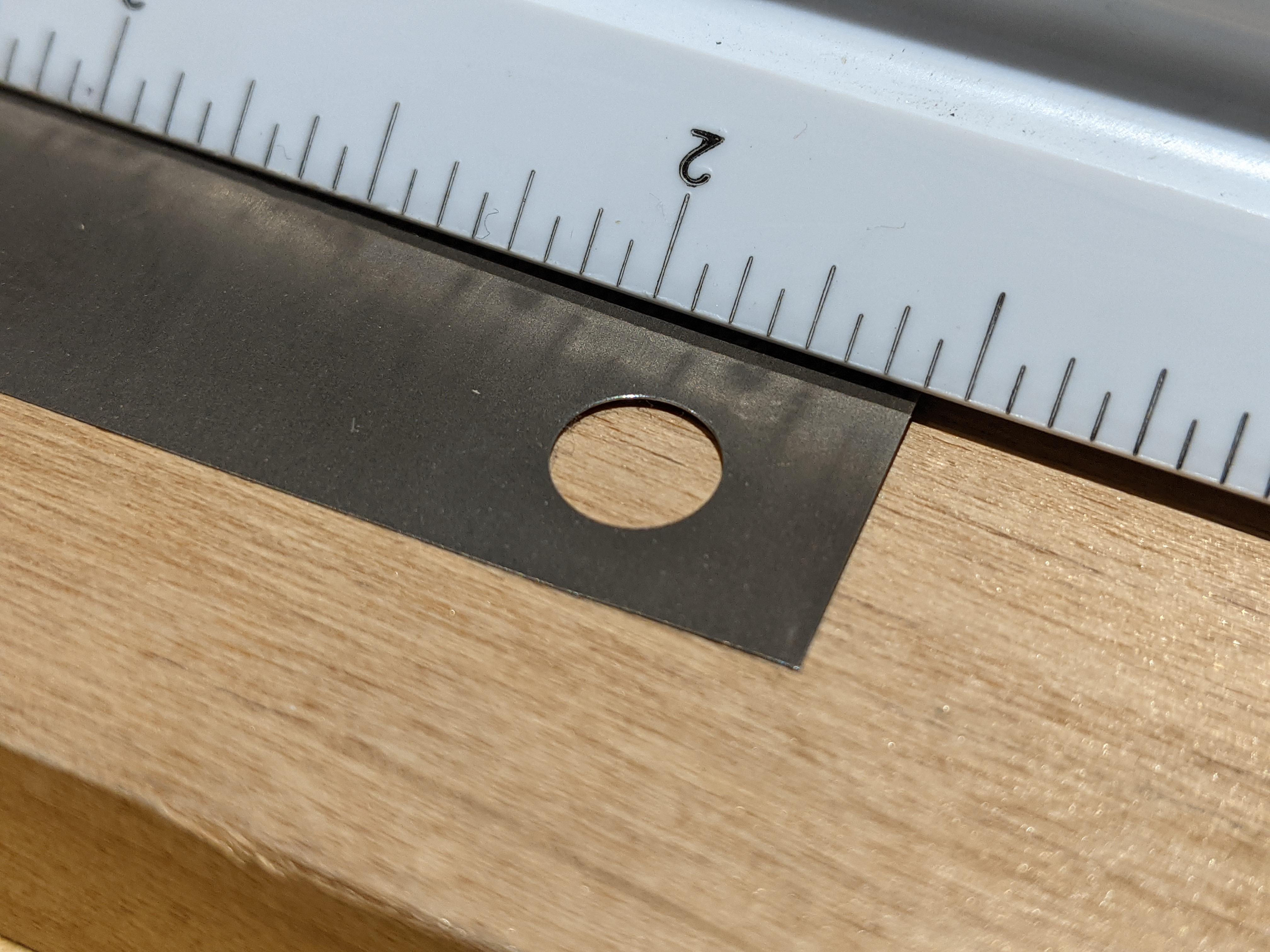
Looks good to me? What diameter? What thickness? What material?
.250″ – or as close to it as the bit will allow – in .005″ 15-3-3-3. I reasoned that if scoring and snapping was a viable way to remove material, then circular scoring should work, too. Hence, the Forstner.
Hi Bozo
Of course you can use bits of scrap steel. I really doubt that 24 gauge steel would work, but anything over 1/16″ should if well clamped.
A (sharp/new) Forstner bit? Yeah, that is (obviously) well worth while trying! Good one.
Cheers
It was semi-new; it’s seen some wood duty, but nothing serious or seriously-dulling. I might just use the scrap that I cut from the main ribbon to see how far I can stretch the bit’s lifespan; normally I would get it resharpened afterwards, but I’m not sure that a .250″ Forstner has enough metal in it to actually sharpen a second time…
Second question, since I’m now deeper into designing this thing: can I bend 15-3-3-3 on a metal brake? I guess I’ll try in the morning when I get back to the shop, regardless. Worst I’ll do is snap a scrap.
Ti-15-3, a shortened designation for Ti-15V-3Cr-3Al-3Sn, is a metastable beta alloy, primarily used where cold formability and high strength are desired. Ti 15-3-3-3 is usually acceptable for use at temperatures up to 550°F (288°C).
The original concept was to develop an economical sheet titanium alloy that could be fabricated by cold-forming operations to reduce manufacturing and fabrication costs and to facilitate repairs in the field. Being strip producible, Ti-15-3-3-3 shows cost advantages when compared with the established alpha-beta alloys that must be hot rolled on hand mills. Whereas alpha-beta alloys also require hot forming in most situations, Ti-15-3-3-3 can be cold formed to quite intricate shapes with improved structural efficiency.
Moreover, the alloy is weldable, ageable to high strength, and relatively insensitive to environments such as saltwater. Finally, Ti-15-3-3-3 exhibits comparatively low directionality and its annealed properties are rather insensitive to process variations.
(Alloys International)
Go for it!
Cheers
Roger
Wow. I would have never thought to use a Forstner bit for thin sheet metal. That’s very interesting.
Wow. I would have never thought to use a Forstner bit for thin sheet metal. That’s very interesting.
Every once in awhile, I have a good idea. This may or may not prove to be one of them. 🤣
Roger, thanks for the the alloy info: I realized – belatedly – that I could probably look up that information, but you made it much easier. I’ll give the tight bend a go in the morning…so now I’m back to trying to figure out how much air intake to create, and how much exhaust space between pot and windscreen…and the more I think about that, the more complicated it gets. I may well just have to take a stab at it and see how it works.
You can often improve the bending performance by putting a padding layer over the top of the Ti so it does not make such a tight bend. Even a layer of thin cardboard can be used in a brake press. You just might need to back the fingers off a bit for the greater thickness.
Cheers
That’s a good tip; I need a bit of extra space in my bends. Thanks!
Well, the bending test was a disaster…but the drilling worked well even when I was intentionally doing it incorrectly.
Bending results:
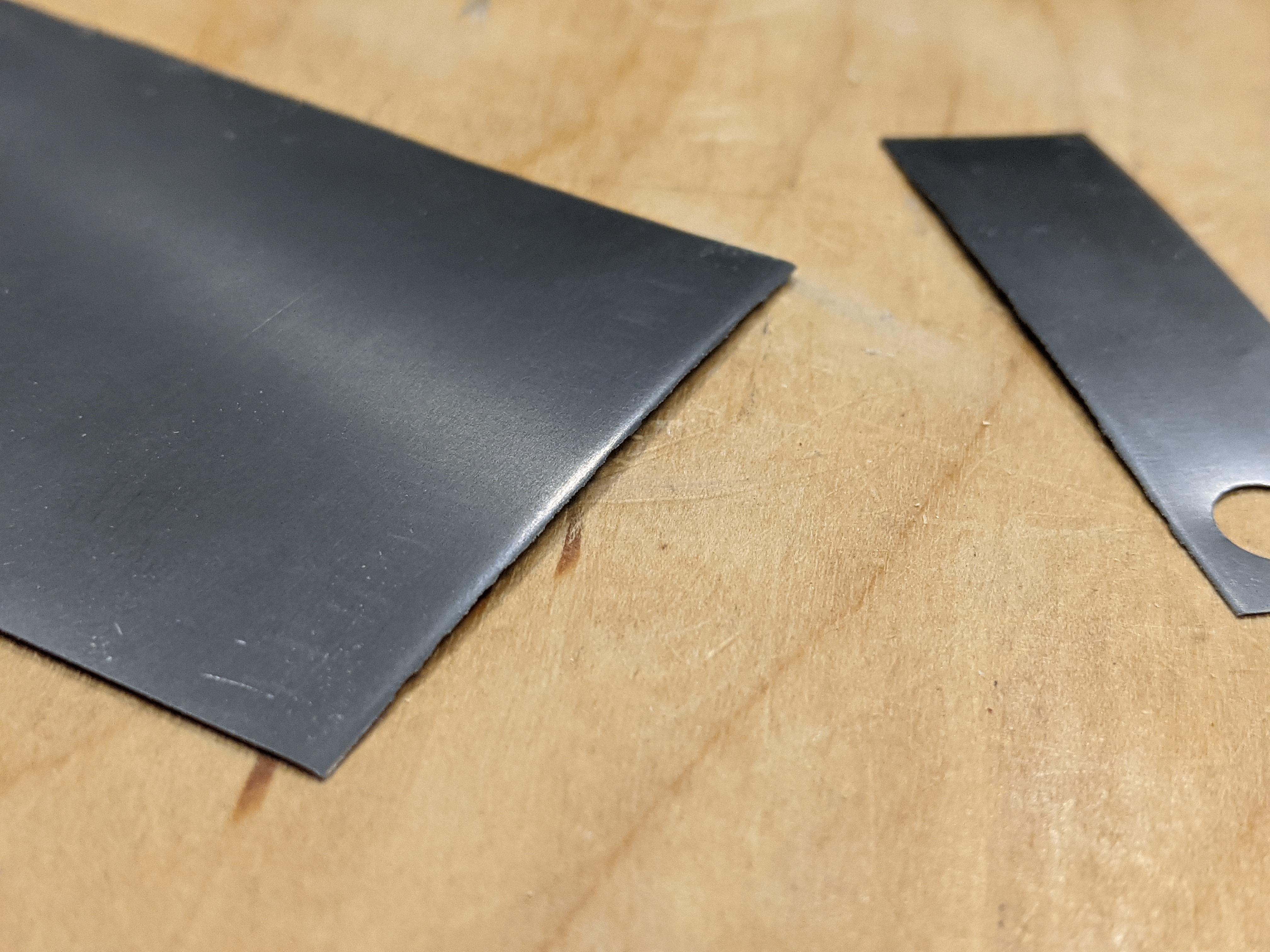
I would call it a clean break, but it wasn’t. It basically cracked apart after it hit 90°-ish on the brake.
Drilling results:
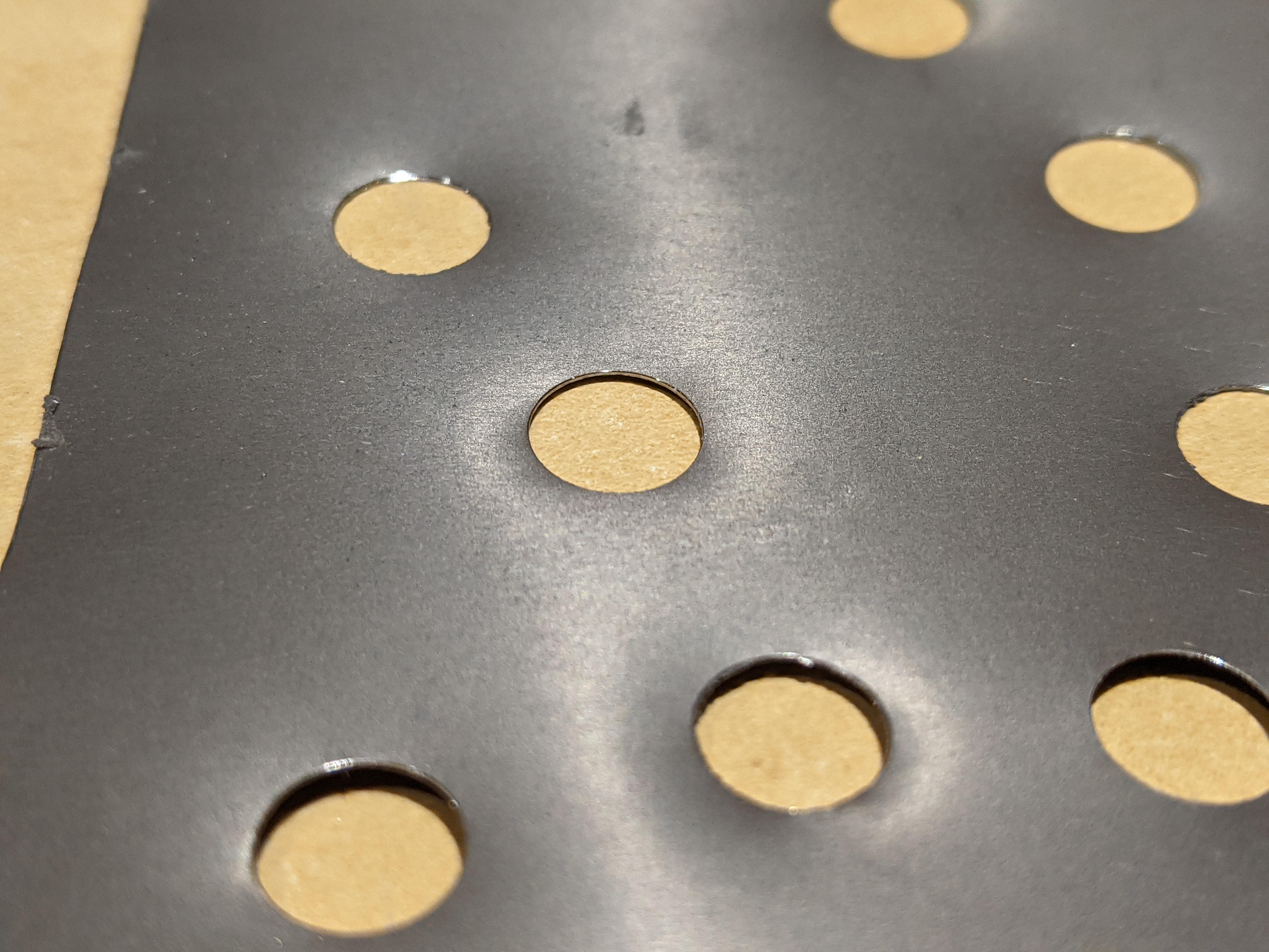
I poked about a dozen holes through this scrap piece: one not-quite-completed hole (not seen here) was intentional: I reused a spot on the backing material to see what would happen. Predictable results: bent material, bad cutting, etc. However, these clean holes were the last ones I drilled: slow, easy pressure until the crinkle-noise signified completion. Very little deformation of the surrounding material (I tried to highlight this as much as possible). I would say that a sharp Forstner works well.
I know this is kind of a drift from figuring out how much airflow area is needed, but whatevs: I figured it was good info to pass on. Now I need to learn how to bend this stuff without shattering it.
That is strange, that it cracked. That alloy is supposed to have good formability.
I have resorted to CP or Grade 1 stuff for that.
Cheers
I thought this was supposed to be a more brittle alloy, but it was REALLY brittle. 🤔
So, I would question what alloy it really was. Ti-15 is NOT meant to be brittle.
Can you bend it over a (say) 3 mm rod without cracking?
Cheers
I’ll have to check on that, Roger; the brittleness concerns me as well. I got some 90° bends that looked nice, and the cracks started after I folded it flat…but I don’t know at what point between 90° and 180° they started. Also, the brake I was using has a knife-like edge; there’s very little radius to it. I’m going to try your idea of using some kind of backing material to soften the radius; maybe a piece of card stock, or something. I also have a nice finger brake in storage; I could easily make a wider-radius edge on one of those fingers, but I’m not sure how well the metal would wrap it when being formed. I feel like I need a press for this kind of thing.
Back to the original topic for a moment: the stove BTU output is 12,600 on full blast, which I don’t use. BTU/airflow calculators don’t help, because this isn’t what they’re designed to calculate. I guess the simplest thing is to keep the total air inlet area close to the same size as the outlet area around the pot, and see how that works.
the cracks started after I folded it flat…
Um. . . . . Oh.
I can imagine the material taking a 90 degree bend, but what happens after that I don’t know! Could the initial bend have caused some crystalisation? I do NOT know.
Could you leave a 1-2 mm hollow core to the full bend?
Cheers
Become a member to post in the forums.
advertisement
Small Business Sales Week

Discover deals from 90+ small outdoor brands during Garage Grown Gear’s Small Business Sales Week.
