I agree about the terms being difficult to work out. I was struggling most to describe the forces and flex directions. If there’s some other term in particular that’s troublesome in my posts, please just point it out and I’ll try to clarify. I hope the sheer length of these posts won’t be offputting…I’m trying to give you a lot to go on now to help you avoid problems and get the best results fastest, so the project gets the most it can out of my limited available time. I know it’s an awful lot of text for just now. I’ll also keep editing to try to make the reading easy and keep hoping it’s not overwhelming.
Let me just hit a few things and see if that’s helped enough to reduce any confusion over what I said enough to make remaining bits more approachable. If something’s impenetrable, please ask for clarification.
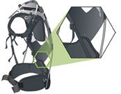
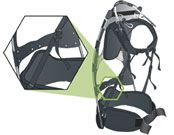
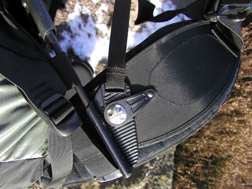
The “wings” I think we’ve been using consistently. Someone has previously noted that Bill has made his sheet metal ones strongest in the dimension they need to be strongest by using the sheet material, the main strength of which is aligned vertically when carrying the pack…and as gravity pushes the pack downwards, the mounts on the hips resist towards the forward extremity of the wings, where the greatest leverage would be had in bending them upwards if they were too weak; that force can be called a “bending moment”. These wings can also effectively form a type of “rib” relative to the plane of the main backpack frame, which is trying to fold under weight, and additional, lower ribs running along the vertical sides of the pack frame and facing front to back like the wings are can add stiffness to the packframe; these ribs can be on either front or back of the frame depending on what clearances require, but it the ribs can be placed so that the largest forces compress rather than stretch them they will provide the needed strength with the least material.
Note how on the Stephenson frame the wings tilt upwards; this is partly to exploit the compressive strength of the tubes and joints, avoiding putting all the force into flexing the joint as would tend to occur if the tubes met the frame at 90 degrees…these parts are stronger in compression than in flexion.. So if the base of the wings (the edge where they attach to the frame) is lengthened, they form a longer rib on the frame, strengthening it more in the main direction we’re worried about the frame flexing (for which we should probably come up with a short discriptive name, I think). And if the base of the wings is mounted higher on the backpack frame, at a greater angle up to the point where the wings are most purely compressed, less material will be required to make wings strong enough to hold up to the forces from carrying the pack. This tilting of the wings is a move from cantilevering towards triangulation.
The strongest structure in resisting a simple bending moment is typically called the “I-beam”…it’s shaped like the most common of building girders, or a letter “I” if cut in cross-section. This I-beam form is a useful basis considering alternative structures, and mechanical engineers often consider how some 3-dimensional form approximates an I-beam when trying to estimate its strength. Imagine a simplified version of hexcore, with two skins around cores that are just a bunch of parallel strips. In terms of resistence to a bending moment along the length of those strips, the planar core board can be considered to be a bunch of I-beams, or nearly ideal for resisting that bending moment with minimum materials if the type and amount of materials and their attachment is ideal.
The resistence to bending moments of an ordinary round tube can be considered as a bunch of partial approximations of an I-beam; the tube’s advantage over the I-beam for some applications is partly in resistance to twisting, but especially in resistance to bending in more directions….but it’s not nearly as strong as an I-beam in the direction that the I-beam is strongest.
Now the “raised ribs” “like waves” that Dale just refered to are something we often see in molded products as stiffeners due to their being relatively easy to mold in and approximating I-beam reasonably well along their length while adding additional stiffness in a few other directions due to their curved forms…it would indeed be hard to characterize those other directions in simple language, and it’s not easy to calculate either, which is one of the reasons structural engineers tend to use old familiar forms, and when they build something out of composites to proceed empirically, that is, by building and breaking things to test them. So we could call those “wave-like ribs”? Seems descriptive. They are also somewhat like like half-tubes.
Now, “triangulation”, which I’ve used as shorthand for “triangulation in space frame structures” or some such term. The single word “triangulation” would make it hard to do a simple Google search since the term is used in so many other ways in geometry, surveying, politics, and so forth. The main idea of triangulation in structures is to exploit the better strength of structural members (such as tubes) in compression as opposed to flexion. Think of tubing racecar frames: here’s an early example: http://www.utahlotusmuseum.com/id267.htm. Notice how in some of the frames’ rectangles, tubes are added that break the rectangular shapes into triangles. This is the “triangulation” of which I speak. A rectangle easily collapses when pushed on a corner, as when dropping an underbuilt loaded external frame pack on its corner when lowering it to the ground. The lowest-material way to stop that collapse and keep the rectangular shape (which may be valuable for other reasons) is to brace the corner of the rectangle that you plan to drop it on to the opposite corner of the rectangle, thereby using the materials in their strongest, compressive dimension.
Why, you might ask, didn’t the external frame designers of old do it this way? Why did they make ladder frames instead of triangulating? There are probably several reasons:
1) they weren’t mechanical engineers and there weren’t as many space frames around to notice when tubular backpacks got going;
2) they weren’t hyper-concerned about getting the lightest possible structure;
3) the difficulty of getting or making non-90-degree tubing fittings was too much, as was fishmouthing tubes at other than 90 degrees,
4), with a simple tubing structure, it’s hard to get the tubes out of the way of the back with simple bends if you run them in an X-pattern across the back;
5) a simple ladder structure gives you a very simple place to mount straps and such; and
6) potential buyers didn’t have superior alternatives.
In fact, later designs did increase triangulation in certain areas. The angling of the Stephenson wings is in fact an example of triangulation of a sort, and it appears in parts of other frames too. Using a frame sheet is also triangulation; it just wastes some material since certain parts of the sheet take more force but the sheet used is typically all the same thickness; you could cut holes or thin the sheet in some particular areas without losing any strength.
Now we have CF layups, which give us more design latitude than do tubing structures. We can put the material pretty much where it needs to be to get maximum strength where it is needed, and not make it stronger than it needs to be where it doesn’t need to be strong, just within the constraints of keeping molding simple and not interfering with the spaces dedicated to such items as arms and packbags. We can also align the the fibers so the structure is strongest against the forces it commonly encounters.
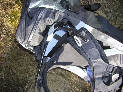
The Mountain Hardware (MH) frames depart from the rectangular ladder structure typical of most older backpack frames. There are some disadvantages to that departure, but also advantages. Let me note a couple of disadvantages, so that if we move away from the rectangle we can be more reminded to compensate for those weaknesses.
1) When you set a rectangular frame down, you can use the bottom corners of the frame to take the abuse and save your packbag.
2) The “square” bottom of the frame can help balance the pack when it’s standing on the ground, and this can fairly readily be exploited to approximate a chair.
3) There are obvious points on rectangles to mount the gear that attaches packframe to human body. Likewise for packbag mounting.
4) More strength may need to be built into the waistband assembly than with a rectangular frame since attaching the waistband to the corner of a triangle at one point creates a longer lever arm between the juncture of frame and waistband assembly. Long lever arms in cantilevered structures like this require more materials to retain strength and adequate stiffness levels.
Advantages:
1)Despite disadvantage #4 above, mounting the waistband assembly to the bottom corner of a frame triangle shifts pack structural weight to a place where the body can probably most easily handle it: around the waist.
2) Again, despite disadvantage #4 above, this mounting arrangement puts a joint right about where I think we’d want if if we need to build some mobility into the joint in order to replicate biomechanics…right around the upper lumbar region. We’d probably want to make this joint stiffer than biology in the fore-aft flexion/extension motion (Dale’s “crunch”), but perhaps leave the top and bottom parts of the pack free to rotate relative to one another in two other dimensions: a) around the vertical axis; b) so the left hip can move up and right hip down (and vice-versa) while the upper pack frame floats along without going up and down on with the hips…similar to the independence of our hips and upper bodies. This can be relatively easily accomplished with two axles. I think this is aligned with Dale’s 05/18/2006 13:26:15 MDT post but I’m not too clear about the pentagons he mentioned and I’ve also been trying to get to some rotation on the vertical axis. I’m seeing triangles because I see the forces that way but pentagons and such might give a better perimeter for packbag mounting than a triangle. But pentagons don’t self-brace to the extent triangles do.
3) The MH structure seems to follow the triangulation I was speaking of with hip motions relative to shoulder motions…it’s basically an “X” shape connecting hips to shoulders.
Compensations for disadvantages:
1) If need be, projections from the frame could be added to absorb forces when the pack is set down roughly, and lighter-duty projections to the ground could be added (or deployed when needed) to make a chair.
2) Careful design can take care of the mounting points for the gear that attaches a non-rectangular packframe to the human body. Likewise for packbag mounting, one would hope.
Improvements over the MH frame:
1) Replacing the hipbelt assembly with a fitted CF structure might save quite a bit of weight and need for (as much) padding. A rigid structure lets us distribute the weight broadly to reduce stress on the body, and concentrate it where we might want to concentrate it a bit (because, e.g., certain parts of the pelvis are easier to get a grip on than others and/or have a preferable combination of bone near to the surface, not too many pain nerves, and so forth.) The waistband shapes they are using might be a little more cantilevered than is required by the single point of attachment to the upper frame; if in building a full-sized model around a specific human body clearances and triangulation are kept in mind it looks to me that a CF layup would allow a more efficiently triangulated hipband structure carrying forces more directly from the hipband to the joint at the upper lumbar.
2) The upper part of the MH frame looks at a glance to have been fairly carefully minimized in its major form according to ordinary structural principles. Using lighter/stronger material would certainly lighten it. Also, they may have used more material than is needed in order to simplify construction, whereas if we look for opportunities, e.g., to use ribs or double-skinned cores instead of sheets of constant thickness if they use something like that, we could save weight.
Questions:
Since the zoom function in my browser is temporaily disabled and I haven’t had time to do the necessary computer maintenance, I’m only seeing small pictures of the MH frames. Are those thin verticals along the outside edge simply straps, or are they rigid? This same zoom limitation makes it a little hard for me to understand quite where the MH parts lie on the body and how stiff they might be in certain sections.
Also, I’m not very clear on how they mount their packbags.
Time limitations are likely to keep me from sorting out drawing issues soon too. I don’t normally draw with a computer so I’d have to set something up, and I suspect that the time required would be such that we wouldn’t get the best out of me on the other issues fast enough to help set directions for projects now.