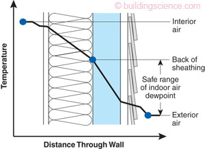
Now, let’s focus solely on a thermal profile, parking issues relating to the water vapor profile and water vapor transport rate.
All models are wrong; and some models are useful. (Not original.)
Thus, carefully list and respect the limitations for any model.
Following is a recitation of assumptions (simplifications) needed to build a simple, perhaps good enough, algebraic thermal model of our sleeping kit (sleeping quilts and bags, possibly layered; hereafter just sleeping kit for brevity) seeking to force icing into an outer, non-down layer.
First, we can have water condensation and ice deposition with our sleep kit WITHOUT being below 32°F ambient, with or without a person inside, with or without a Vapor Barrier Liner (VBL). We call these events dew and frost, and they occur due to radiation cooling into deep space when the ambient humidity is great enough. Thus, let’s assume usage of a covering tent or tarp to eliminate radiation cooling. This matters significantly for the outer surface temperature of the kit.
Next, our sleeping kits are NOT solid, isotropic thermal barriers with uniform thickness. They are not like a solid piece of metal or polymer. They do not have true-solid-phase resistance (or conductivity) for heat (or mass) transfer, and they are not uniform in thickness.
The true physical reality of our sleeping kits is a complex, non-isotropic structure of varying thickness. Sure, we often use the simplifying modeling and calculation concept of equivalent, lumped-effect R-value resistance, as if the insulation were a solid, isotropic material; but this is not reality.
Our sleeping kits provide insulation principally by restricting the macro, meso and even micro scale circulation of air, but down plumes and synthetic batting do not fully eliminate these movements of gas molecules.
(For deeper appreciation, reflect on goose down plumes vs. eider down plumes of equal loft rating; vacuum thermos-bottle type insulation; closed cell foam vs. open celled foam; a sleeping kit made of 3- or 4-inch-thick aerogel; Alpha direct insulation vs. Apex at the same thickness; etc.)
With that understanding, what else can disturb/augment gas molecule motion inside the sleep kit?
· External wind if strong enough can penetrate some fabric layers (and it can even move the shape of the kit causing “breathing” around the neck, for example.)
· A person breathing (thorax expansion and contraction) and especially a person tossing and turning continuously change the natural air movements inside the insulating layers.
Thus, let’s add 2 more simplifying assumptions: de minimis wind and a static human.
Let’s assume planar geometry.
· Cylindrical coordinates are closer to truth, though still not reality; but cylindrical coordinates cause messy calculus – and messy algebra after other assumptions.
· A planar assumption is not self-evidently apt without further understanding; for, seemingly strangely, adding ever thicker insulation on cylindrical piping can lead to more heat loss instead of less.
· However, for the dimensions of a human body and for a typical sleeping kit with de minimis wind, analyses not covered herein recommend that planar coordinates are a useful modeling simplification.
Assuming planar geometry also implies negation of the head and foot zones of the sleep kit. Of course, we know this is not true. The head zone can be particularly important for a quilt without a draft collar. All such air-leakage zones (and entrance zones) are particularly important to the total heat loss and the temperature (profile) inside the sleep kit. (Moreover, an AMPLIFIED ditto applies for the mass leakage of water vapor since the water vapor content near the body is non-linearly greater than in outer layers of the sleeping kit.)
Assuming planar geometry also means assuming a uniform thickness of the sleeping kit, or else we are back into multidimensional modeling. Of course, thickness is not at all uniform: sewing and baffles are real, maldistribution and thin spots are real, and these flaws have disproportionate heat loss (and water mass loss). This is essentially a repetition of issues for the head and foot zones; but it applies to the entire surface of the kit.
Assume uniform temperature on the inside surface of the sleeping kit. Of course, we know that this is not true: feet get cold, body & clothing touch sleeping kit in some places but not others, etc.
Assume a uniform temperature on the outside surface of the sleeping kit. Of course, air currents and boundary layer resistance to heat (and mass) transfer are variable over the surface of a sleeping kit, even without any wind, because of natural convection due to the pseudo-cylindrical shape.
Assume completely uniform lumped-effect thermal resistance of the sleeping kit, with insulation and fabric combined into a single effective lumped-effect average value.
If more than 1 layer is used, make some sort of assumption about the contact and air currents where the 2 quilts interface. Furthermore, assume that this thermal linkage is invariant over the adjacent surfaces of the 2 layers. Of course, we know the 2 quilts are not bonded together and that they do not have uniform connectivity over their respective adjacent surfaces.
For simplicity, assume that there is not any added thermal resistance at the boundary of the two layers. (Optionally, since there actually is added resistance from any air pockets at the boundary between layers, one can add a bit of thermal resistance for the boundary by including it with the resistance of either the outer or inner layer.)
Assume the sleep event is long enough to reach a steady state thermal profile.
Assume that the heat capacity of air is about constant, so that usage of a single average value causes the term to cancel out from the energy balance ratio used hereinafter.
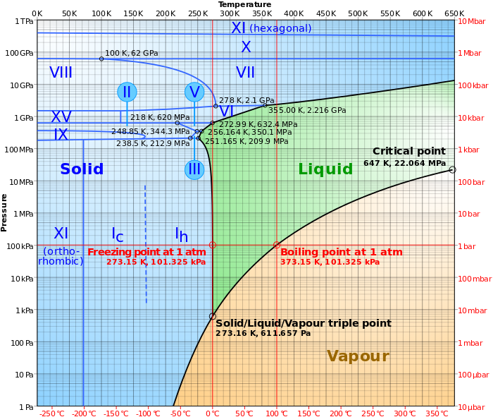
(We do not need to make any assumption about elevation (system pressure) because we are not dealing with the mass transport of water vapor; we are just considering thermal profile.)
Whew! With all these modeling assumptions, and perhaps more overlooked, there are relatively simple algebraic formulae for thermal profiles in multilayer insulating systems. These have already been recited by others within BPL, but they are now repeated.
Quilt 1 (inner) has uniform, lumped-effect average resistance of R1.
Quilt 2 (outer) has uniform, lumped-effect average resistance of R2.
Quilt 1 has an actual uniform inner surface temperature of T1.
Quilt 2 has an actual uniform outer surface temperature of T2.
The temperature Tb (temperature at the boundary between the 2 layers) is modeled as follows:
(T1-Tb) / (Tb-T2) = R1/R2
(T1-Tb) = (Tb-T2) * R1/R2
Usefully, the units of R1 and R2 cancel out.
For example, we can explore a case where R1 ~ 6 (ft2-°F)/(BTU/hr) and R2 ~ 2 (ft2-°F)/(BTU/hr), or 7 and 2.5, or whatever – if we have useful estimates of the respective R-values.
Optionally, if we can estimate that the (thermal resistance of insulation per unit thickness in Quilt2) = k * (thermal resistance of insulation per unit thickness in Quilt1), then we can compare the ratio of R1/R2 based on the thickness of each layer without even knowing actual R values.
E.g., R1/R2 = (thickness layer 1)/(k *thickness layer 2), with k an empirical value.
Next, we come to the thorny issue of the actual values to plug in for the inner (T1) and outer (T2) temperatures. Even though we have already assumed that each is invariant over its respective planar surface, we have yet to grapple with the actual values of T1 and T2.
The inner temperature is particularly fraught. Is the person naked or wearing clothes, and how many layers of clothes? If a person is an ultralight hiker wearing most of their carried clothing to bed, including down parka and down pants, we are dealing with at least a 3-layer system. Sure, the above algebra extends to 3 layers; but this extension comprises yet another set of simplifying assumptions, and we will still be faced with needing to estimate a uniform temperature over the inner surface of Quilt1.
To cut through the issue of insulation from worn clothing, let’s postulate a consideration for when T1 is about 92°F. Conveniently, 92-32 = 60°F dT from inner to freezing at atmospheric pressure. (Chose a different value for T1 if you wish, and proceed accordingly.)
Next, let’s say that we want to know what value of outside temperature produces a value of Tb that is exactly 32°F. The algebra for the model with all the above simplifying and focusing assumptions becomes:
T2 = 32 – (92-32)* R2/R1 = 32 – 60*(R2/R1)
The following table shows different ratios of ever thicker layer 2, i.e., ever greater R2 compared to R1. If inner and outer layers have the same thermal efficiency per unit thickness, the values can also be viewed as thickness ratios.
R2/R1 T2 (when T1 = 92 °F, Tb = 32°F)
1/5 20 °F
1/4 17 °F
1/3 12 °F
1/2.5 8 °F
1/2 2 °F
1/1.5 -8 °F
1/1 -28°F
However, in the real world: winds do change the actual surface temperature T2; worn clothing does change actual inner temperature T1; variations in thickness of layers and in how they touch do occur; etc. for all the other simplifying assumptions. I expect at least ±5°F variation in actual field (anecdotal) results compared to the above table.
Still, it’s a useful guide (as others found long before me).
· If we want to force icing into the outer layer only, the inner layer cannot be too thick relative to the outer (e.g., cannot use a 5” down layer with a 1” Apex outer layer at 0°F)
· The colder the ambient that we wish to endure, the thicker and thicker the outer must become to keep icing out of the inner.
· The more clothes one wears inside layer 1, the thicker layer 2 must become to force icing outside of layer 1 and into layer 2 .
· When the outer layer ices, R2 will decrease and Quilt2 will require airing/deicing or the freezing boundary will creep ever inwards.
Corrections on errors and oversights are surely welcome.
 at which water vapor leaves the sleep kit.