Topic

BRS Failure (photo)

Viewing 7 posts - 26 through 32 (of 32 total)
Bonzo BPL Member
PostedAug 19, 2025 at 10:02 pm

What does ‘bend’ mean?

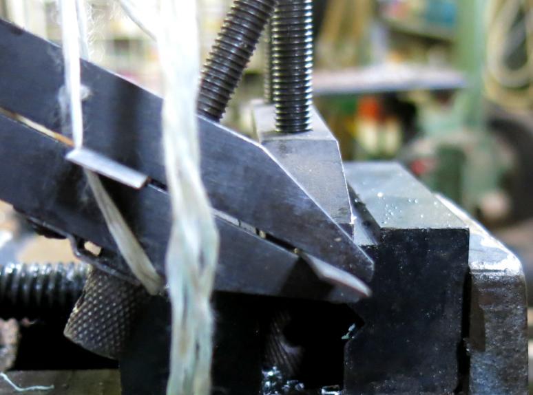
In this case, it simply referred to the area that failed on the most visible pot support: the one on image right.  It looks to be pushed downward around 30°, both by my estimate and that of the AI; hard to tell from the photo.  I don’t see much of a twist; if that occurred, it would stack with the other forces.

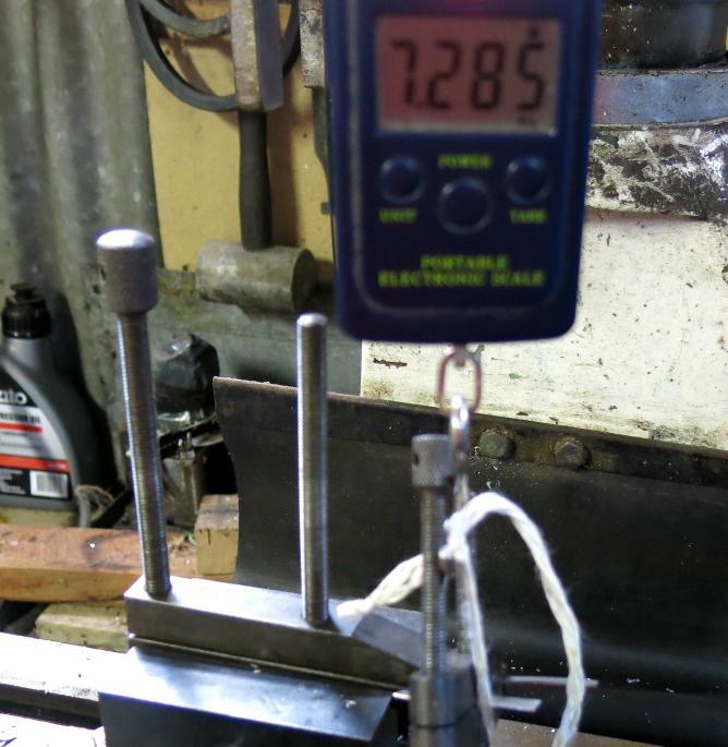
Regarding the difference between a simple 10° bend and…well, anything else: it looks like one could assign a 1.5x factor to the ~2.5kg estimate…and after plastic deformation begins, c’est fini.

Grade 5 was used for the estimate.  Grade 23 is pretty close in strength.  Grade 9 is about 75% of Grade 5…

…and now that I’m thinking back on it, I’m pretty sure that I stopped using my BRS because I accidentally bent the support flange downward while unfolding one of the supports.  Totally not making that up; I just now remembered that one of the rivets was stiffer than the others, and when I was unfolding that leg one evening, the flange underneath just deflected downward.  I pushed it back into place and had no further issues, but I haven’t used it since.  Now I really want to find that thing.

Roger Caffin BPL Member
PostedAug 19, 2025 at 10:48 pm

Hi Bonzo

Fish your BRS-3000T stove out and have a close look at the support arm. It is twisted in the ‘failures’, not simply bent. Check it out.

Yes, of course (I think) one could damage a BRS-3000T stove by hanging a full house brick (~7 lb) off one arm. But who would do that?

Cheers

Roger Caffin BPL Member
PostedAug 21, 2025 at 8:29 pm

OK, “he said, she said” … gets nowhere.

So I decided to (gasp shock horror) actually measure the force required to get a twist like that. The lug on the BRS-3000T measures about 1 mm thick, 6.2 mm wide and sticks out a somewhat tricky amount but let’s say 4 mm, before the lug transitions into the larger support ring. The tip of the pot support is no more than about 35 mm from the middle of the lug; the inside edge is about half that – say 17 mm.

I cut up a bit of 1 mm Ti sheet to 6.2 mm wide and clamped it carefully. I marked off a point about 4 mm from the clamp, put a second clamp at that mark. Then I marked off a distance of 35 mm from the edge of the Ti. This should fairly closely approximate the worst case for the actual stove. The rig looked like this:

I mounted the 1st clamp in the vise in my manual mill and hooked a cord to the 2nd clamp at the 35 mm offset. This cord went to a fish scale attached to the quill, which had been lowered. The bit of aluminium sticking out keeps the string at the 35 mm point.


(Sorry about the poor focus: all a bit tricky in the poor lighting.)

Then I allowed the quill to go upwards slowly, while I watched the readout on the scale. I allowed the twist to get to about 30 degrees, which is what I what seen in some of the other photos. See the 1st photo to understand.

The fish scale registered 7.9 – 8 kg force (about 17.6 lb) at the tip of the pot support to get that twist. A repeat run of this gave the same result. If a pot had been giving this force, the point of contact would have quickly shifted to the inside edge of the top of the pot support, meaning a force more like 16 kg.

Now, an Australian clay house brick traditionally weighs about 7 lb, so the force was about 2 1/2 house bricks – on one pot support arm. I leave it as an exercise for the reader to figure out how one gets this sort of force on just one pot support.

Cheers

Bonzo BPL Member
PostedAug 21, 2025 at 8:54 pm

That’s a pretty good test, Roger; nice work.  It’s a little hard to follow because of the way the images were taken, but I think I have enough understanding of it to see what you’ve done…and I’ll certainly accept those results as valid.  Thanks for doing that and repeating the experiment.

I think that even if we can’t know exactly how the damage in question was caused, we can at least speak to what kind of physical forces would likely be necessary to create it.

Also, Roger: I now understand what kind of twist you were talking about.  In my mind, I was seeing a simple bend, but that’s clearly not what was happening; after looking at all of the images again, I have no idea why I didn’t understand this to begin with.  Furthermore, running your numbers in the same material GPT that I previous used – Grade 5 at 1mm by 6.2mm by 30° twist with a 35mm lever arm – resulted in 6.1kgf, and I think that’s close enough to show that your testing protocol is valid.

Dan BPL Member
PostedAug 22, 2025 at 6:21 am

Post of the year by Roger. This is why we need “likes!”

Jerry Adams BPL Member
PostedAug 22, 2025 at 7:54 am

Good test!

I wonder if it gets hot enough to weaken it.

It would be nice to get a photo showing the failed part

Viewing 7 posts - 26 through 32 (of 32 total)
Loading...