Topic

Project: 4oz 1A USB Charger


Forum Posting

A Membership is required to post in the forums. Login or become a member to post in the member forums!

Home Forums Gear Forums Make Your Own Gear Project: 4oz 1A USB Charger

  • This topic is empty.
Viewing 25 posts - 51 through 75 (of 140 total)
  • Author
    Posts
  • #1916167
    Wizard of Oz
    Member

    @wizardofoz

    Locale: New England

    So I had intermittent clear skies here so I got outside with the actual solar panel to see how it all came together. I forgot to bring the iPhone cable that I could hack up so I didn't implement the .5A/1A mode switch yet, or test it out with a real phone but i used dummy loads purposefully made just under 5 and 10 ohms to make sure I reached full current draw.

    So what do you want first, the good news or the bad news…

    THE BAD:
    1A mode is not possible with this panel! At least least not with the sun this time of year. The sun was very string about 1:30PM today, but try as I might with angle and waiting patiently for zero cloud cover. I could not reach full 1A output! So I think that, as is way too common, the manufacturer is just a little optimistic. Looking closer at the powerfilmsolar website, it's supposed to output 15.4V at .3A, which is actually 4.62W and at a clean 90% efficiency of my converter in perfect sun, that's only 831mA. Now I didn't see just how much I could have pulled, but suffice to say, my circuit CAN handle 1 full Amp, the panel couldn't provide that much power in the sun today. (BTW, the open circuit voltage on these little panels is 19.4V!)

    So I've decided to nix the 1A/.5A mode switch option. Oh well, there something to be said for simplicity

    THE GOOD:
    500mA output was fantastic. even with the sun behind a very descent cloud such that I could stare at it without getting fully blinded, it was still able to pump out the .5A! So yea, you need sun to charge, but I won't have to worry about perfect positioning and babysitting too much, which is good news for me, even if it's not quite as fast as a wall charger.

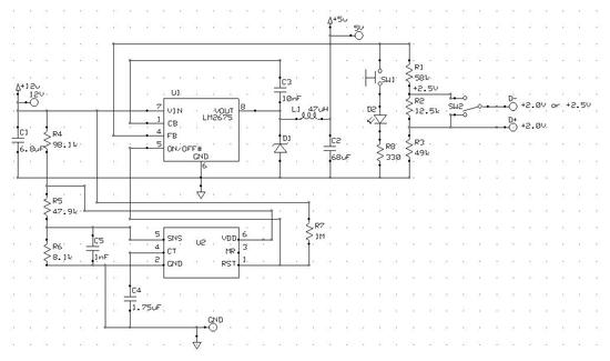
    I also found a pretty cool little device to help with the low sunlight turn-off oscillation issue. I played with capacitors and such, but they didn't really fix the problem. So another Texas Instrument special (seriously, I'm not affiliated in any way, they just make great stuff), a TPS3808, come to the rescue. It's a supervisory circuit that draws VERY little power and can be set up to have a 10s delay on the Step-Down Converter On/Off pin. So I ordered that and I think it'll really help solve that issue! Basically if the sun goes behind a big enough cloud that I love panel power below some level that I can choose (8V), it'll shutdown the converter circuit for 10s, then try to power it back on again, and see if the sun is back. I'll keep you posted on that, but it looks very promising.

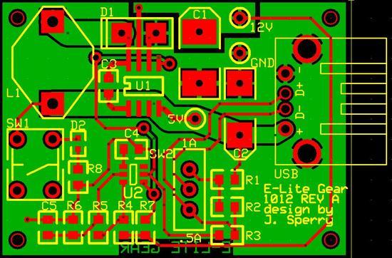
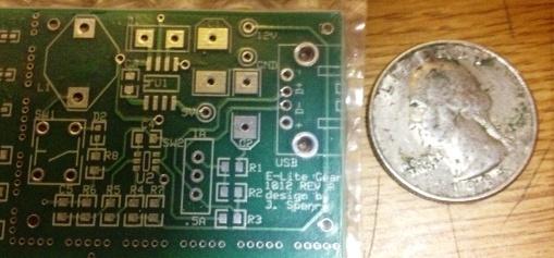
    THE UGLY: well currently the state of the my breadboard…since it's all in test setup mode right now, but it's been a great tool in figuring out little details. I really want to have a custom PCB made for final version of this as a nice icing on the cake.

    THE FUTURE: I'm running a 'drain' test right now to see if the circuit will kill my battery if accidentally let plugged into the solar panel over night or something. I really don't want to add diode to block back current and it looks like I won't have to. Preliminary measurements say that it is drawing no current backwards at all! but I'm going to leave it for a hour and half or so in airplane mode and see what happens.

    So other than figuring out the detail on the low power shutdown circuit, all the testing that remains is to do a charge time test. I should be able to drain my phone enough by tomorrow to do a full charge through the circuit and I'll let you know.

    #1916173
    Jerry Adams
    BPL Member

    @retiredjerry

    Locale: Oregon and Washington

    You ever buy components from digikey.com?

    I've bought stuff from them and they have more selection and cheaper than local "brick and mortar" places

    #1916218
    Jack Elliott
    Member

    @jackelliott

    Locale: Bend, Oregon, USA

    Pity about the panels not being powerful enough for 1A operation. Are we married to 0.5 or 1A options? Could you try for .75A?

    But anyway, nice job — and good idea about using that supervisory IC.

    Once you get the thing debugged, maybe you could post schematic and BOM?

    #1916323
    Roger Caffin
    BPL Member

    @rcaffin

    Locale: Wollemi & Kosciusko NPs, Europe

    Hi David

    Ahhh, techie stuff :-)

    > Ideally one would rewire a 3-row, "12-volt" array of 0.3 amps into a 5-volt, 0.9 amp array
    > by changing the rows of cells from being in series to being in parallel
    Um – that's not quite as easy as it sounds. One can have problems if the cells are significantly mismatched. However, putting a Schottky diode in series with each one can solve that problem. The voltage drop is small.
    Yeah, that's a thought, but the 12 V panels I have seen here seem to be rather integrated, so that rejigging them might damage them. But I know I have not seen anywhere near the full range of what is commercially available.

    Cheers

    #1916338
    Wizard of Oz
    Member

    @wizardofoz

    Locale: New England

    Yea, I definitely love digikey! newark online is my other favorite if I actually have to break down and 'buy' parts. My favorite is the free sample places :) TI and other big names are great at sending samples of 1 or two chips out, then I just have to find or buy the small caps and such that go around them.

    Jack, you've motivated me to try a bit more. Unfortunately there's no sun today…But I did hook up both the 1A and .5A modes on the bench with the actual iPhone 4S and they worked great. The current draw on each is right on spec by less that 10mA difference from expected. Of course this is using a lab power supply for my 12V rather than the panel.

    I let my phone die this morning, so I'm running a full charge up time test in .5A mode right now. It's been 25 minutes and I'm already up to %21 percent. so I'm guessing it'll be an hour and a half.

    When I get some more sunny days, I'm going to try the solar panel in 1A mode with the actual phone, just to see what happens, but my guess is that since my circuit is a voltage source and not a current source, it won't work. The StepDown regulator is trying to output 5V and when the phone tries to draw the 1A, it will shut off, not just fold back the voltage. Not knowing exactly what the internal circuitry is on the iPhone, you never know though.

    It's a rainy weekend here in MA, so I probably won't get to test out the new shutoff circuit till next week. I'll definitely be posting a schematic and material list in the end with whatever I find works best. I'll likely have some left over ICs and maybe a few extra custom PCBs as a minimum buy if anyone wants to claim them for a few bucks.

    #1916358
    Wizard of Oz
    Member

    @wizardofoz

    Locale: New England

    Two updates:

    1. Started from a completely dead iPhone 4S with the charging circuit on .5A mode. 100% charge reached in 94 minutes!

    2. I forgot to post this before, but this circuit does NOT drain the iphone when it's not powered (i.e. no sun), so no diode is needed!

    #1917149
    Jack Elliott
    Member

    @jackelliott

    Locale: Bend, Oregon, USA

    So Oz, does the iPhone only give two options, 1A and 1/2A, and won't recognize or use 3/4A?

    Great results so far.

    #1919091
    Wizard of Oz
    Member

    @wizardofoz

    Locale: New England

    Received that last IC I was waiting for to help with the low light issues. The TPS3808 works like a charm! It completely takes care of the oscillation and gives a variable 7-12 sec pause when the panel voltage drops below 7.6V before trying again, but ONLY once the panel voltage comes back over 8V! Really nice! So the circuit is highly efficient (90% measured!), has a very bright 'output check' LED and a 1A-.5A switch onboard. Even though my panel isn't powerful enough to actually power the 1A mode, I figured I could use this in the future with another panel or if someone develops a better lightweight, flexible, and weather resistant photo panel :)

    I did go ahead and keep the USB output port, so I can charge other devices or a AA batter charger with that port. i was going to hard wire in an iPhone connector to save a few grams, but figured the versatility was worth it, plus I suppose this will now work with the iPhone 5's new connector since you can just plug a different cable into it. Or a Droid, Samsung, BB, etc.

    Anyway, the final board size is 1.275" x1.725"!

    Here's the parts I used:
    USB A Female Connector
    C1 6.8uF Sprague 594D685X9050D
    C2 68uF Sprague 594D686X9010C
    C3 10nF 50V Ceramic
    C4 1.75uF 1.75uF ceramic
    C5 1nF 1nF ceramic
    D1 Diodes Inc B120B
    D2 LED LED 9mA
    L1 47uH Coilcraft D03316P-473
    R1 58k 58.5kohm
    R2 12.5k 12.5kohm
    R3 49k 50kOhm
    R4 98.1k 98.1kOhm
    R5 47.9k 47.9kOhm
    R6 8.1k 8.1kOhm
    R7 1M 1MOhm
    R8 330 340ohm
    SW1 NC Momentary ON
    SW2 SPDT
    U1 LM2675 National LM2675-5.0
    U2 TPS3808 TI TPS3808G

    And the Schematic:
    Final Schematic

    I have 6 board being made and have enough SMD parts for at least 2 of them. here's the board layout! Soldering will be TOUGH!
    PCB layout

    I should have everything by Thursday and I'll let you know my progress. I've got a 16 mile training hike this weekend, but I should be able to find time to get started. Let me know what you think. I'll throw some pics up of the work in progress. And if anyones wants to buy a board off me (bare or assembled), just let me know! Where else can you get a sub 4oz 5W Solar Charger :)

    #1919444
    Jack Elliott
    Member

    @jackelliott

    Locale: Bend, Oregon, USA

    Wiz, you wrote, "And if anyones wants to buy a board off me (bare of assembled), […]

    Is that "bare of assembled" or "bare or assembled"?

    'Cause I'd buy an assembled board.

    #1919457
    Wizard of Oz
    Member

    @wizardofoz

    Locale: New England

    Good catch Jack! Fixed that typo…

    What, you don't want to do all that miniscule soldering, haha! Yea, I had to buy the board in a batch…well it cost the same whether I got 1 or 6, so I got 6. I can definitely assemble an extra one for you. I'll just ask for the cost of PCB and parts, which is about $30. I hope to have mine done early next week if everying arrives as expected and I'll get it tested to make sure everything works. Then I'll get another one together for you. The only thing you'd have to do is to solder in your solar panel wires right to the board, or if you want I could put some small 6" wires on there hanging with bare ends so you can connect by whatever means to your panel if you don't solder.

    Who else! 1 is spoken for, 4 more available :)

    #1919465
    Jerry Adams
    BPL Member

    @retiredjerry

    Locale: Oregon and Washington

    You should charge more – enough to pay for yours for example – like $60

    #1919471
    Wizard of Oz
    Member

    @wizardofoz

    Locale: New England

    I like your thinking Jerry! But I'm just looking to make sure the design gets some use at this point. This is fun for me. If 40 people want these, I can do them up with the the full solar panel and all and actually charge for a final product. But I'm guessing a full up solar panel/board/ and the mini-case that I'm going to do to protect the board will be like $110 when all said and done!

    #1919872
    George Geist
    BPL Member

    @geist

    Locale: Smoky Mountains

    > I can definitely assemble an extra one for you.
    > I'll just ask for the cost of PCB and parts, which is about $30.
    > I hope to have mine done early next week
    > Who else! 1 is spoken for, 4 more available :)

    Hi Oz,
    I'll take one of the 4 remaining. And I'm happy to pay for
    not only the PCB and parts, but your labor for assembling it.
    You can contact me at gst (at) ornl (dot) gov

    I was wondering if you ever had a chance to test the ThinkGeek
    plug to see how it's efficiency compared?

    Al

    #1919932
    Wizard of Oz
    Member

    @wizardofoz

    Locale: New England

    Board 2, SOLD to George :)

    I didn't end up testing the ThinkGeek cigarette lighter to USB adapter. Basically since I couldn't get even a full 1A out of my solar panel, I didn't see the need to test an even higher capacity circuit. And I'm pretty happy with 90% efficiency I was able to acheive! No need for greener grass other than pure curiosity. Plus when the low light oscillation because an issues, I pretty much knew that a custom solution would be best for the device I'm charging so I'm not strobing it like a little kid standing at a light switch for the halloween party.

    I'd still be curious to try it out someday for comparison!

    #1920158
    Jack Elliott
    Member

    @jackelliott

    Locale: Bend, Oregon, USA

    P-mail sent.

    #1920174
    Wizard of Oz
    Member

    @wizardofoz

    Locale: New England

    You got it Jack! Thanks for all your great comments and suggestions during the design too! I got confirmation that the boards are on their way to me and should arrive tonight. I'll let you guys know when they are together and working and get some pics up too!

    #1921358
    Wizard of Oz
    Member

    @wizardofoz

    Locale: New England

    Bare boards made it in and look shiny and green…until I started to goop them up with flux :) They came out REALLY nice and I'm pretty impressed with the quality of the PCB House! The detail is really clean.

    Here's a pre-cut pic:
    Bare Board

    Didn't get time to do a full assembly yet. I've got two parts that are delayed, but hope to have them early this week, and have the first one fully together on Tuesday. I did get the 'toughest' parts on the first one though, you can see just how SMALL the ICs are. The pains we go through to save weight… Everything soldered on really nicely since the board was so new and tinned.

    I didn't clean it yet cause I want to do that all at once, but here's the first partial board!Partially Assembled

    #1921377
    Jack Elliott
    Member

    @jackelliott

    Locale: Bend, Oregon, USA

    Ain't it nice to get your board back from the house, and start putting parts on it? After staring at the board design on the monitor, holding the real thing in your hand is quite rewarding. Even better is powering it up and seeing no smoke!

    #1921456
    Bob Gross
    BPL Member

    @b-g-2-2

    Locale: Silicon Valley

    Many years ago, it was not so easy to buy complete printed circuit boards like this one. For one thing, everything was through-hole soldered then. Now I see this one is part through-hole and part surface mount. That makes it harder to stuff the board.

    I used to make my own single-sided boards from scratch. Those were the good old days. Ahh, yes, the smell of hot ferric chloride solution…

    And then, you want to think about weatherproofing this thing. We used to use a full potting compound to make the entire thing into a plastic brick. That is probably unnecessary now, but a clear spray that hardens might be useful as long as it doesn't add much weight.

    –B.G.–

    #1921457
    Matthew Naylor
    Member

    @mrnlegato

    Locale: Mid-Atlantic

    Bob, Are there any specific spray products that you recommend for this kind of thing? And does that lead to any problems with overheating?
    Matt

    #1921462
    Bob Gross
    BPL Member

    @b-g-2-2

    Locale: Silicon Valley

    There probably are some spray products, but I don't know the current ones.

    When we were less sophisticated, we would simply paint on clear fingernail polish to any exposed conductors.

    If you had components that were radiating a lot of heat, then the coatings can become a problem. However, I'm guessing the high efficiency means that there isn't that much heat radiated, so coatings wouldn't be a big deal. If you do full encapsulation, it can become a big deal. I did that badly once about forty years ago, and I had a smoking hole in the middle of the encapsulation plastic.

    If you get too much protectant gooped onto the circuit, then you might have a maintenance problem. You can't easily hook test clips onto it anymore.

    I guess it all boils down to the environment that you intend to use it in. Maybe this thing needs to reside in its own cuben fiber bag.

    –B.G.–

    #1921525
    David Thomas
    BPL Member

    @davidinkenai

    Locale: North Woods. Far North.

    How about the spray version of Plasti Dip?

    http://www.plastidip.com/

    The can I have says, "flexible, won't crack" "insulates electrical shock, vibration" "provides non-slip grip" and "resists weather, chemicals, impact and abrasion".

    That's been my experience with it. I've used multiple coatins to provide more cushioning on tool handles, but you can make it even thinner by adding xylene or toluene.

    I concur with Bob's thoughts on overheating. Definitely a consideration, but with a high-efficiency circuit, there's not much power to disapate.

    #1921547
    Bob Gross
    BPL Member

    @b-g-2-2

    Locale: Silicon Valley

    What David said about flexibility could be important.

    If you had the wrong stuff, when it dries it might "force up" a surface mount component. With flexible stuff, it wouldn't have such force.

    Think about it the other way around. If you got the circuit cold enough (high in the mountains), it might have unpredictable problems with the cold. But, with an extra layer of waterproof insulation on it, the cold problem can't last long.

    –B.G.–

    #1921664
    Jack Elliott
    Member

    @jackelliott

    Locale: Bend, Oregon, USA
    #1921701
    Steve G
    Member

    @sgrobben

    Locale: Ohio

    I have successfully used "hot glue" but am not sure how it compares in weight to other solutions.

Viewing 25 posts - 51 through 75 (of 140 total)
  • You must be logged in to reply to this topic.
Forum Posting

A Membership is required to post in the forums. Login or become a member to post in the member forums!

Get the Newsletter

Get our free Handbook and Receive our weekly newsletter to see what's new at Backpacking Light!

Gear Research & Discovery Tools


Loading...