Introduction
This Part 4 is a post-construction analysis: how well does the design work, or possibly how ‘does it work’? It also covers a whole lot of ‘minor’ performance details at the end, which details actually can be quite significant in the field.
Heat Flow
A key requirement for a liquid feed stove is the flow of enough heat into the incoming fuel: it is essential that the fuel gets thoroughly vaporised before it reaches the needle valve. You do not want liquid fuel going through the needle valve: it creates all sorts of mini-fireballs outside the jet. They are not good for eyebrows and tents.
The first part of the problem is that you can’t easily calculate the heat flow: you have to build a stove and measure it. I know one could do a Finite Element Analysis for the heat flow – but that requires a full knowledge of the heat inputs and outputs and the gas flow. A super-computer would be nice, but probably inadequate. Hah! The second part of the problem is the amount of development work and machining jigs needed to get one stove made so one can do the testing. Ah well: it keeps me out of mischief (or so my wife says).
Early models were tested with a finger. It’s not hard to tell whether something is frosty cold – <0 C. That’s the Frozen Finger test. You have read of the ‘Touch Test’ for 40 C? When you touch something at 40 C you tend to go ‘Ouch’ and remove the finger. Canisters can always take 40 C, but you should not exceed that. There is also the ‘Pfzzt’ Test for 100 C. Experienced stovies will know what that is. But moving on from there, we need measured data.
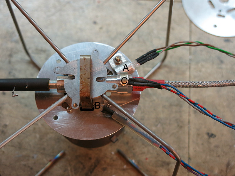
Data Logging arrangement
Subsequent more refined stoves were tested by actual measurement, using LM35 temperature sensors and a LabJack T7-Pro data logger (thank you Toby of Labjack). The edge of the Stove Base Plate (A), the side of the central block of the Stove Body (B), and the nut on the Hose Connector (C) were the main monitoring points, as well as the top of a large Campingaz CV470 canister near the Lindal valve. Special clips were made to hold the LM35s against the aluminium stove parts for good sensing. While the contact area was limited in some cases, there is little heat flow away from the sensors (minor convection and down the wires), so they should be very close in temperature to whatever they are clipped to.
All results were roughly corrected to ambient. Doubtless there are small errors of 1 or 2 degrees centigrade here and there, but they don’t matter in the present context.
Background
The big round Stove Base Plate (sensor A) is heated by conduction down from the Burner Chamber through the washers and M2 bolts, by direct contact with the flames inside the burner chamber, and it will also get radiant heat from the flames, the top of the glowing burner chamber and the very-definitely glowing splash plate. The plate loses heat by conduction to the Stove Body (lots) and by convection (air flow) to the outside world (less). It is expected to get hot quickly: it does. However, the temperature the Stove Base Plate reaches is not particularly important by itself, although it can be around 100 C. Pfzzt! Don’t touch.
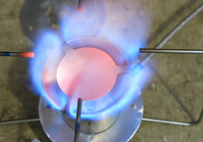
Stove roaring away full bore
The square central block of the Stove Body (sensor B) is heated by conduction from the Stove Base Plate through 4 small aluminium support pillars and 4 steel screws. The 4 small support pillars conduct a lot less heat than full contact over the whole top surface of the stove body would. This heat flow may also be impeded by layers of insulation (red fibre washers) placed between the support pillars and the Stove Base Plate, although in winter conditions they are not needed. There is also quite a lot of heat coming in through direct radiation and flame contact to the jet and the central boss. The central block does get hot.
The central block of the stove body loses heat to the needle valve handle (insignificant as it goes almost nowhere) and to the Hose Connector, and through the latter to the incoming liquid fuel. This latter is <i>very</i> important. This means the Hose Connector (sensor C) is possibly the most important measurement point. The hose connector receives heat from the central block by conduction and loses heat to convection (only a small amount) and to the vaporisation of the liquid fuel. Whatever temperature the hose connector is at will be very close what the liquid fuel sees as it reaches the heat exchanger section, before going through the needle valve to the jet. This temperature needs to be greater than +10 C, although +20 C is better for good vaporisation. As we will see later, the heat loss to the fuel is quite significant. Very definitely you do not want the hose connector failing the Frozen Finger test.
Heating Dynamics

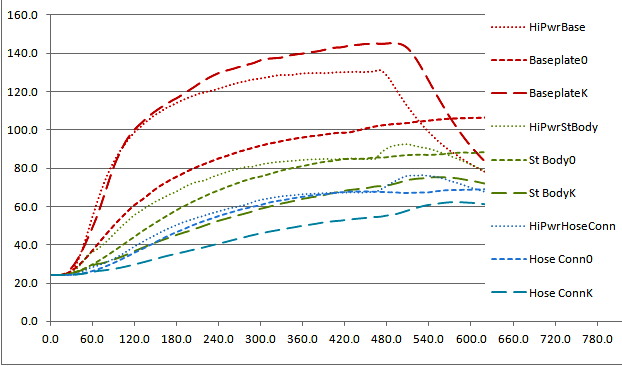
Stove heating up with differing amounts of thermal insulation
When the stove is lit the various temperatures are expected to shoot up quickly at first, then level off as equilibrium is reached. The greater the amount of insulation between the Stove Base Plate and the Stove Body (eg red fibre washers), the less the heat loss from the Stove Base Plate to the Stove Body and so the greater the heating rate for the Plate. Red is for the Stove Base Plate (A), green is for the Stove Body (B) and blue is for the Hose Connector (C). The suffices on the labels show how much insulation there is between the Stove Body and the Stove Base Plate: 0 layers of 0.5 mm thick red fibre washers, 2 layers, 4 layers, and finally K which is a thick insulator of a different material. Treat the K insulator as being close to ‘no conduction’: it’s close. OK, there will still be some conduction down the length of the steel screws, but steel is a poor conductor. In addition, there will be heat going directly into the stove body from the jet, which is heated by the flames. The stove was lit shortly <i>after</i> the zero time on the graph (I have only 2 hands.) Stove power is ‘Low to Medium’: a gentle cooking power. More than that tends to be wasteful of fuel.
The Stove Body and the Hose Connector will heat up at a rate which should at first glance be determined by the temperature of the Stove Base Plate and the amount of insulation. However, it seems that the rate of heating is not affected all that much by the amount of insulation, although the equilibrium temperature does vary a little bit according to the amount of insulation. Adding 4 layers of thin insulation (0.5 mm red fibre washers) is enough to drop the equilibrium temperature by a bit under 10 C, which really is not all that much. (Propane flame temperature is close to 2,000 C or 3,600 F in air.) My interpretation of all this is that a lot of the heat comes in directly through the jet, while the small area of the four support posts is a major limiting factor in the heat transfer from the plate. This latter was intended (honest). I remembered that full contact on the V2 stove gave far too much heat flow at first, and that some standoff and insulation had been really necessary.
However, while the Stove Base Plate temperature can easily head up towards 140 C (serious pfzzt territory), it seems that the Stove Body is limited to under 90 C and the Hose Connector is limited to under 70 C in practice. There is little physical distance between the latter two, so the temperature differential has to be due to a distinct heat flow. This heat flow is driven by the boiling of the liquid fuel near the Hose Connector end and inside the Heat Exchanger section.

Coleman Xtreme stove, photo by Coleman
Could I get the fuel to vaporise inside the hose, before it reaches the hose connector? The Coleman Xtreme stove does this by running a thin brass rod up the rigid bit of the fuel line (blue arrow) just before the heat exchanger pipe goes over the top of the flames (red arrow), but that works for that design because the rigid fuel line is supported by the rigid leg it is clipped to. Actually, the Xtreme is a brilliant design which very few people really understood. I could get some heating of the fuel if I ran a copper wire from the aluminium heat exchanger inside the stove body up the hose, and I have done that on the V2 stove. However, in this case I held off doing this to see whether it was really needed. To cut a long story short: I don’t think it is needed.
These results are all with the stove on approximately the same low/medium power and an ambient of 24 C (Australian summer) in my lab. If the ambient was dropped to, say, -6 C, all the curves would drop by 25 – 30 C. It would take the Hose Connector a little longer to reach an adequate fuel vaporisation temperature: that’s what priming is all about. That said, in winter I remove the red fibre washers for faster priming, so it is not that slow. However, it is worth noting that the Stove Body warms up a bit more and a bit faster than the Hose Connector, so we can expect that the fuel will still be vaporising sufficiently before it reaches the needle valve tip within a minute or so. Instead of this happening right at the Hose Connector, it will be happening somewhere along the Heat Exchanger – which is what is meant to happen. And yes, this has been field tested way below freezing: see below.
This extrapolation to -6 C assumes the canister has been allowed to cool down to ambient. If some care has been taken with how the canister is handled and stored, we can expect it to start at a much warmer canister temperature. My canister is carried in my pack next to my back and my water bottles, so it is rarely below 0 C when I take it out. I quickly wrap it up in something like my quilt to keep it warm until I want to cook. But even if it does cool down a bit it can be warmed up again: I can put it in a bowl of water for a bit before the stove is lit. That means the fuel may be starting around 0 C, and the canister presure will be higher. The vaporisation temperature will be reached quickly.

Field testing at around -7 C (1,600 m) showed that the stove primed quite quickly (10 – 20 seconds) at low power. Warm milk for muesli breakfast came quite quickly. I think the current arrangement is sufficient.
However, one customer of my V2 stove had huge problems with priming: his stove continued to fireball way up in the air no matter what he did. Eventually he sent me a video of how he was priming, and the problem was immediately obvious. He was trying to prime at full power (to get it going faster), and the stove was just not warming up. Evaporation of the big load of incoming liquid fuel was sucking too much energy from the stove body, and the big rush of air through the air inlet holes in the stove base plate was cooling that down as well. What flaring was happening was outside the burner chamber and not warming it up very much. I dare say the stove might have sorted itself out eventually – at a high cost in fuel and nerves.
I persuaded him to try priming at low power. It worked just fine on first try.
High Power
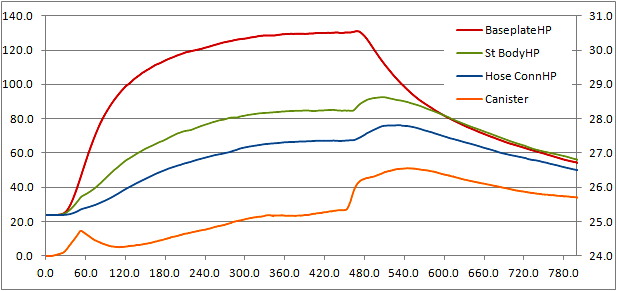
The interpretation of this next graph is the same as for the previous one. I have omitted some intermediate curves for clarity. It compares the previous Medium setting with the High Power setting.
Thermal behaviour at high power
Let us look at what happens if you enthusiastically ramp up the power as soon as the priming is done. You may well get some mini-fireballs at first as drops of liquid fuel come out of the jet (despite the priming), but clearly the Stove Body is going to heat up quite a bit faster (as long as the flames are heating the burner chamber). One might call it ‘flaring’ rather than ‘fireballs’. The high power performance is shown by the dotted lines, and there is no red fibre washer insulation used (as for insulation code 0).
But there are several interesting things shown here. The first is that the round Stove Base Plate does not heat up significantly faster at high power with no insulation (dotted line) than at low/medium power with serious insulation (long dashes). The lack of a large difference was a bit unexpected at first. We know that the burner chamber is heating up pretty fast and getting pretty hot at any power setting (it glows red), and the spacer washers between the burner chamber and the Stove Base Plate are limiting the conducted heat flow. The amount of heating of the Stove Base Plate from direct flame contact inside the burner chamber is about the same anyhow, and may be dominating at the start. Well – it would be, considering how close the flames are to the base plate! Radiation downwards will become significant as the splash plate starts to glow.
It is interesting that the Stove Base Plate reaches a slightly lower equilibrium temperature at high power than it does with the heavy insulation at medium power. I interpret this to mean that the greater amount of air being dragged in through the air inlets in the Stove Base Plate at high power is actually doing some cooling of the Stove Base Plate. That was genuinely meant to happen after all, but it is gratifying to have some confirmation.
The Stove Body heats up a bit faster at high power – possibly reflecting the faster temperature rise of the Stove Base Plate. This is to be expected, and is fine. There may be more heat inflow through the jet at high power as well. The same applies to the Hose Connector, the curves for which are partly obscured. But, and this is a very important point, the equilibrium temperature the Stove Body is headed for is about the same for high power as it was for low/medium power. If more heat inflow is available, from the hotter Stove Base Plate and hotter jet, but the temperature stays about the same, there must be more heat loss at high power.
The obvious path for greater heat loss is the incoming fuel which is being vaporised. We will come to this shortly.
Heating after Shut Down
Some strange bumps may be seen in the data for the Stove Body and the Hose Connector at the right hand side of the above graph. The bumps start at the point where the stove was turned off (at the control valve on the stove). The Stove Body and the Hose Connector actually get hotter quite fast for a short while when the gas is turned off. What is happening here?
The temperature of the Stove Body is set by a balance between heat coming in from the very hot Stove Base Plate (and even hotter Burner Chamber) and heat going out into the vaporisation of the incoming fuel. When the stove is turned off at the control valve the heat loss to the incoming fuel ceases very quickly but the incoming heat flow (from the burner chamber and the Stove Base Plate) continues, so the Stove Body now heats up much faster. However, note the way the temperature of the rather light Stove Base Plate is falling: as it falls towards the temperature of the Stove Body the Stove Body stops getting hotter, and starts to cool off like everything else. Naturally, the Hose Connector temperature tracks the Stove Body temperature.
Canister behaviour
A similarly interesting thing happens to the temperature of the canister, shown here. For this experiment the canister was allowed to receive radiation from the stove, rather than being hidden from it outside a windshield. I recommend this arrangement in any cold weather. The graph shows only the High Power data, with the canister in orange and its scale at the right. The steel shell of the canister is being measured by an LM35 at the top of the canister near the edge of the Lindal valve. This is well above the top of the fuel inside the canister at the start, and there is not much ‘communication’ between the steel at the top and the fuel at the bottom in this half-empty canister. The steel shell is after all a poor conductor. At first the top of the canister shell warms up due to radiation from the burner chamber, while the fuel inside down at the bottom is cooling due to evaporation. Then at around 60 seconds the canister is inverted, the cold fuel hits the warmer steel wall where the sensor is, and the sensor temperature drops.
Since the fuel is no longer evaporating inside the canister (liquid feed now) there is no heat loss inside the canister from boiling, and the canister and the fuel both start to warm up again (see from about 120 seconds onwards) due to the radiation from the stove. At 460 seconds the fuel supply was switched off at the canister and the canister was turned upright again. With no fuel in contact any more, the steel shell at the sensor starts to warm up again rather fast from radiation from the stove. Then the stove goes out and the radiation warming ceases, and the canister starts to cool again.
Why is there a short the delay between the canister being switched off and the Stove Base Plate starting to cool? That is the difference between controlling the gas flow at th stove/jet and trying to control the liquid flow back at the canister. There was liquid fuel in the hose and it took a while for that to be used up. So when you turn the stove off at the canister the behaviour of the stove lags the behaviour of the canister, by the time it took for the hose to be emptied of fuel. It is not a big deal. You can try to anticipate this in the field, but it is tricky.
Safety
Given all the above, is the stove safe to use with or without the insulation? The answer is yes, to both. The highest temperature recorded is just above 90 C, in one of those bumps. For the aluminium metal in the block and needle valve this is a trivial temperature: an aluminium frying pan in the kitchen gets significantly hotter than that every time you use it.
But what about the other materials used? The materials in contact with the aluminium stove body are Viton O-rings, PFA tubing and either a plastic control knob or some carbon fibre tubing.
* The Viton O-rings are rated to 200 C for continuous operation. That is adequate clearance above the 90 C. I use Viton rather than the cheaper nitrile because it has a slightly higher rating.
* The PFA tubing used is rated to 260 C for continuous operation at zero pressure. At 24 C it is rated for use up to 2,700 kPa (400 psi), at 100 C it is rated up to 1300 kPa (190 psi) and at 200 C up to 710 kPa (103 psi). A typical workshop compressor gets to just over 100 psi. Note that these are ‘RATED WORKING PRESSURES’ according to the vendor: actual BURST pressure for this tubing is about 5 times higher than these figures. That’s an engineering safety margin, and a considerable one too. The highest pressure a commercial canister should reach at 25 C is about 520 kPa (75 psi), which is a small fraction (19%) of the rated working pressure of 2,700 kPa for the PFA at that temperature. Basically, PFA is good stuff!
* The resin in the carbon fibre tubing optionally used for the handle extension should be able to handle up to about 110 C, or possibly a bit more. That depends on exactly what the resin is. Note that the resin is thoroughly reinforced by the 2D-wrapped carbon fibre filaments. As the exterior of the tube gets a fair bit of air cooling, this should be adequate. Field testing has not shown any problems.
* The clear plastic handle on either the Ti wire or the short aluminium handle should be able to take 110 – 120 C without problems. It does not seem to get hot in ordinary use: the plastic may be transparent to IR radiation. The reason for the other longer handles was that you might find the proximity of the glowing burner chamber a bit too much for your fingers. But if you don’t mind – then the short handle is fine. In the field I have used all three and the tips of my fingers to adjust the valve.
A further safety factor which is not obvious is the sensitivity of the valve. On the V3 it takes about half a turn to go from ‘off’ to ‘full power’. A typical commercial stove might take about 1/8 of a turn or even less for the same range of adjustment. I find that with many commercial stoves, by the time I have cracked the valve open to light the stove, it is going at full power. The better needle valve design used in the V3 stove allows me to light the stove at a very low power – which is much safer.
Stability and other things
 Stability of the pot
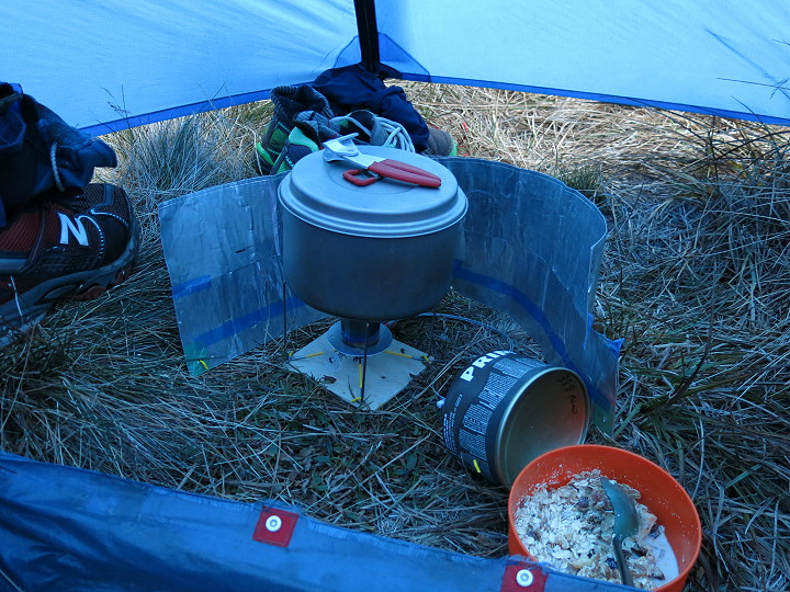
The third photo in this article is repeated here. It shows the stove in the field. I had been warming up some water to make warm milk for breakfast. I had used the stove like that for dinner the evening before as well. At no stage did the pot seem at all unstable. I was able to stir the dinner without holding the pot, although I make it a practice to always hold the pot with the grips while I am stirring. Fishing dinner out of the snow grass is so messy, and you risk kneeling in it when you get out of the tent.
You can see in the photo that the windshield goes around the pot and the canister. I find this a useful arrangement as it warms the canister just a bit. Normally I have the concave base of the canister facing the stove to protect the nylon/acetal canister connector, but nothing ever gets all that hot anyhow. In this case the canister was the other way around.
One thing I had not fully anticipated was the virtue of the much smaller 3-ply base plate you can see here. I often use a 3-ply base plate for the stove, but so often it is hard to find a suitable clear horizontal area for the larger base plates. This one is so small it fits in between the snow grass tufts quite easily. And you may note the tiny yellow hooks going over the legs at the corners of the 3-ply: they are micro-stakes made of 1.6 mm Ti wire holding the stove down, through holes at the corners of the 3-ply. The resulting stability is great. The same stakes are being used to hold the windscreen in place so I don’t accidentally knock it flying when I am tired.
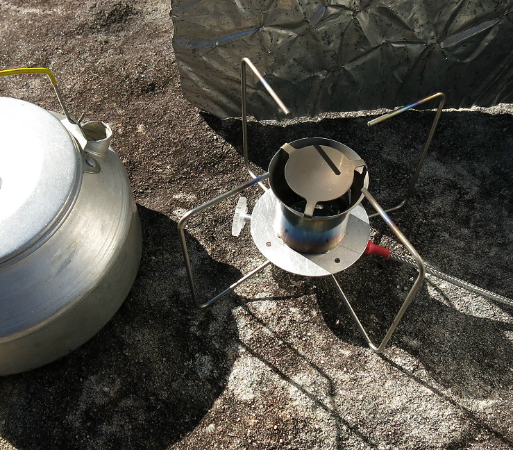
Stove on sheet rock
However, if I am cooking on sheet rock I can’t get the micro-stakes in. (Ti is good, but not that good!) Instead I find a smooth flat spot and carry on, as shown here. Yes, the windshield in this photo is a different one and looks a bit crinkled: it is the one that lives in my day-walk pack and is probably well over 10 years old. 10 hard years … and many cups of morning coffee.
I have been field testing some Primus Winter Gas canisters which we reviewed in the middle of 2016. Sadly, I have to report that even the Primus brand seems to have some dirt or something in it these days. I had to clean the jet on the evening of the third day of the trip up the mountains (photo of stove inside tent above) as it was obvious that the jet was partly blocked. Slacken 4 screws, remove burner chamber with a 5 degree twist, remove jet with tiny spanner, inspect by looking through it (yes, dirt was visible), clean with pricker, replace. It only took a few minutes to return to proper operation, but the dirt did annoy me – especially as you would expect that a canister labelled ‘Winter Gas’ might be used inverted.
We have a whole series of articles on CO emissions. (The URL here is to Part 1 of 6 parts.) My summary for many stoves is that anything which gets too close to the burner face can quench the flame and create CO. Under normal use the tips of the visible pot supports on the V3 do get red hot, but the glow does not extend to anywhere near the bends. This means that there is very little opportunity for CO to be emitted, and some basic testing with a CO meter has confirmed that. The stove is a low-CO emitter by design.
Since the bends never get very hot, that also means the pot supports will stay very strong. I have heard tell of some little titanium pot supports on some Asian stoves getting red hot and then bending a bit. I don’t think that will happen here.
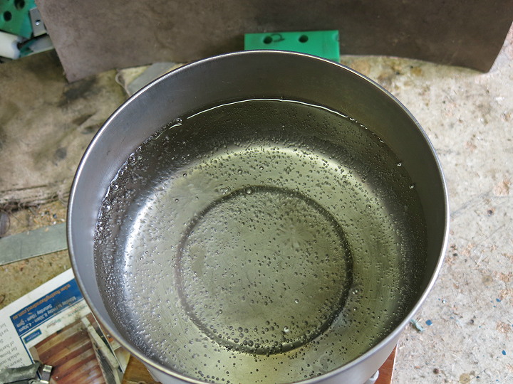
Flame spread and boiling pattern
Finally, flame spread. Unlike some commercial stoves which have very narrow flames which can easily burn your dinner (Pocket Rocket maybe?), the flame on a Vortex burner is spread out and distributes the heat over a wide area. You can see the really wide pattern of bubbles here as a pot comes to the boil. This does mean that a narrow beer can pot is not going to work too well, but they are very inefficient anyhow.