Topic
DIY Backpacking Stove: An Ultralight Vortex Burner (Part 2: Research and Development)
Forum Posting
A Membership is required to post in the forums. Login or become a member to post in the member forums!
Home › Forums › Campfire › Editor’s Roundtable › DIY Backpacking Stove: An Ultralight Vortex Burner (Part 2: Research and Development)
- This topic has 34 replies, 8 voices, and was last updated 8 years, 7 months ago by
 Roger Caffin.
-
AuthorPosts
-
Jun 29, 2016 at 2:22 pm #3411414
Companion forum thread to: DIY Backpacking Stove: An Ultralight Vortex Burner (Part 2: Research and Development)
In part 2, Roger Caffin explains the research and development behind the vortex burner as a solution for an ultralight winter DIY backpacking stove system.
Jul 6, 2016 at 7:43 am #3412594I don’t think IR will reflect off the burner chamber.
Maybe a parabolic shape of the chamber would emit a little more up towards the cooking pot, but the IR that’s absorbed on the sides isn’t wasted – it heats up that metal which then re-emits.
I bet burning efficiency is the main factor.
And, I wonder what Roger thinks of Trump? Brexit?…
Jul 6, 2016 at 4:14 pm #3412743Hi James
Yes, I do understand about IR radiation. (Retired PhD research physicist, remember.)
The parabolic shape – easy enough to make in drawing brass if you have a large press. After all, that’s how most of the commercial Vortex Burner stoves do it. That was the only viable technology available to Primus when they started making such stoves, way back when. But try making that shape in Titanium (which is (what I wanted to use). I think there are three ways you could do it:
* Forming red hot Ti (and I do mean RED hot)
* Machining out of solid (the time and cost …)
* 3D powder metal laser sintering (the cost of such a machine)None of these are commercially viable in my workshop!The thing is, the Burner Chamber design I have ended up with (as outlined in Part 1 & 2) WORKS, works well, and is manufacturable by me. The rest of the design will be revealed in better detail in the forthcoming Parts of the series.
Cheers
Jul 6, 2016 at 4:19 pm #3412744Hi Jerry
The IR will reflect off the Ti metal, and be absorbed and reradiated. However, it doesn’t matter, as ultimately the energy has to come out of the stove. Efficiency is fine, and the burner can simmer gently as well as roar.
Cheers
Jul 6, 2016 at 8:07 pm #3412777Roger, No, you missed it. You can slit the side and draw the rest.
Sort’a like working with sheetmetal to form a curve, ‘cept you are working with a cylinder.

In practice, you can simply make a slit then die it down to the correct diameters in a press. Of course you have to allow for the thickness of the metal, over-bending as needed and possibly inserting a steel screw/rivet to hold it (but a little leak is OK.) As I mentioned it will act as a vortex in the combustion chamber. insulating the sidewalls also. High heats will eventually degenerate the Ti. Centering the bends will be the worst of the problems.
Jul 6, 2016 at 10:38 pm #3412792Hi Jim
No, I didn’t miss it. I have already tried doing what you suggest, and I have to report that it ain’t easy! It is easier to form the alloy used in the tube than the 6Al-4V alloy, but only slightly. Very large forces are still needed.
I would have to develop new steel dies for this, and hope that a 10 ton press is sufficient for the forming job. I have some reservations, but maybe. Many months of work would probably be required.
I would have to ‘seal’ the joint line to prevent local oxidation and corrosion. While the surface of the Ti tubing does develop a very effective protective oxide layer very quickly on open surfaces (humidy helps, believe it or not), Tim Clarke’s experience is that tiny pin-holes through the metal do ‘burn’ out rather quickly. I suspect that the butt joint on the surface would behave in a similar manner to tiny holes. So, how to seal that joint (or several joints)?
I don’t think there are any ‘sealants’ which would handle the high temperatures AND the thermal cycling.
I don’t think ordinary spot welding would work here.
You can’t braze this stuff.
MIG welding might work – after a lot of practice at sheet metal welding, but I don’t have a MIG welder and I have no experience there either.
An electron beam welder would probably work, but I don’t have one (and cannot afford one either).But more to the point, what would the design gain?

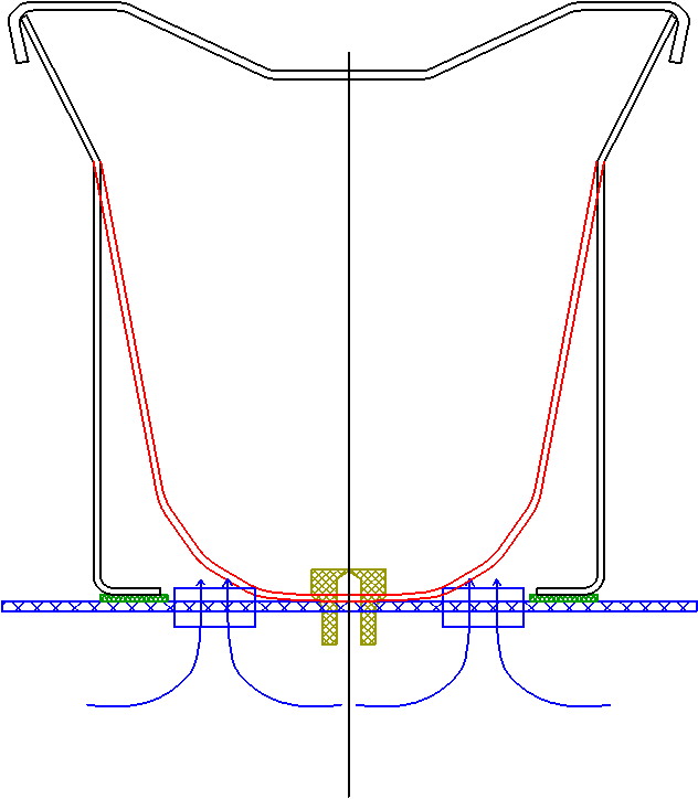
I have superimposed the parabolic design (red) onto the parallel tube design (black) here. The volume difference in the corners is small – remember that the OD of the tube is only 38 mm. The flames are kept out of the corners to a large extent by the flow of air in through the inlets as shown. The main part of the flame vortex is up near the splash plate anyhow, although burning up the middle certainly happens.
So – given all this, would the behaviour of a conical/parabolic burner chamber be all that much different from one made from straight tubing? I have to say I cannot see that there would be any real gain for all the hassle.
But I might be wrong. Perhaps someone might like to make some parabolic chambers for testing? I would be very willing to give them a test!
Cheers
Jul 6, 2016 at 11:19 pm #3412798Roger,
Have you seen these?

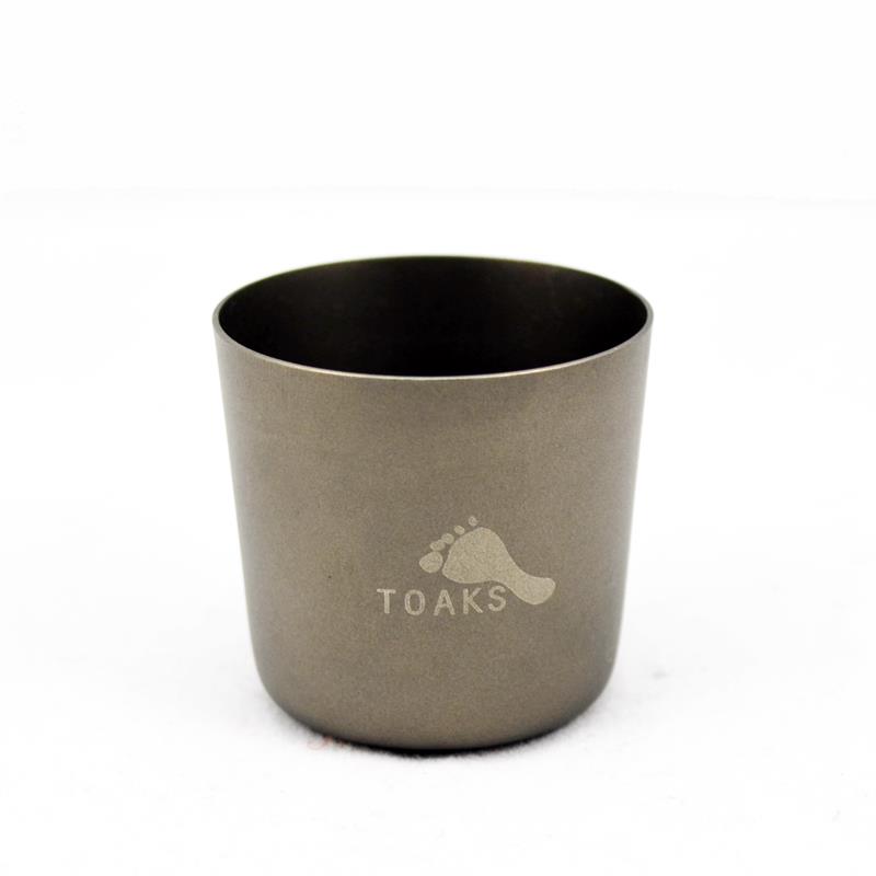
I am pretty sure that they are a CP Grade and if so it would be pretty easy to reshape. 38 mm at the top and 10 grams is a good starting point. Best wishes.
http://toaksoutdoor.com/titaniumshotglass.aspx
Jul 7, 2016 at 12:32 am #3412807F AS C I N A T I N G
No, I had not seen them.
Some of the Chinese titanium fabricators are getting VERY good. They seem to be able to make stuff which can not be made in USA. Does anyone worry about this?The shot glasses are more expensive than the tubing, and I would have to develop a new set of dies for the flaring. But very interesting all the same. I have copied the page for some consideration, thank you!
Cheers
Jul 7, 2016 at 3:34 am #3412815Roger,
“I would have to ‘seal’ the joint line to prevent local oxidation and corrosion. While the surface of the Ti tubing does develop a very effective protective oxide layer very quickly on open surfaces (humidy helps, believe it or not), Tim Clarke’s experience is that tiny pin-holes through the metal do ‘burn’ out rather quickly. I suspect that the butt joint on the surface would behave in a similar manner to tiny holes. So, how to seal that joint (or several joints)?”
I do not believe so. As I said, a small screw will work on the overlap pinning the two bends together. OR, you could leave it loose and create a vortex air inlet. Two might work better than one. This will cycle around the burner (by centripetal acceleration) cooling the whole burner. I would guess about 200C solving the overheat problem. IR would be reflected up and out along the whole chamber, increasing efficiency rather than just dumping heat secondarily. Welding, brazing become superfluous. Necking it down, and centering it, become the only real problem.
Yes, I read Tim’s articles. I believe his burnouts were caused by localized combustion at the surface. Your stove does not do that. It burns in a donut…well a vortex. Almost all the combustion has happened before the heat has rotated around.
Jul 7, 2016 at 7:21 am #3412845Hum … interesting ideas.
I suppose it’s me who is expected to do all this too? :-)
I will think about it for a bit, especially the dies needed. Mind you, that Toaks shot glass is also an interesting idea.In the meantime I have to replace a substantial part of the roof of my barn/workshop. It’s probably >100 yrs old, the iron has rusted so the roof leaks, and some of the battens are a bit light and a bit old. The rafters – are straight sapling trunks – well, mostly straight. My CNC lives under al this. Ah well.
Cheers
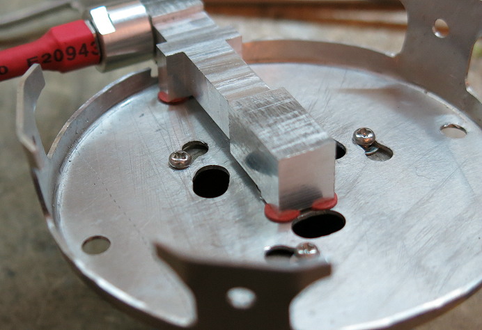
Jul 22, 2016 at 7:08 pm #3415751One of the photos in the article shows a layer of red fibreboard between the Stove Body and the Stove Base Plate. It was effective, but I have not been able to find where to buy the stuff today. What is shown is some of my ‘old stock’ from 20+ years ago.

However, while I cannot find bulk red fibreboard for sale, I was able to find small washers made of red fibreboard (on eBay of course). So now I put 4 of these between the body and the base plate, as shown here.
Close examination of the stove body will show that it has been machined away for most of the contact region between it and the base plate, to reduce the contact area as well. Now the body is attached to the base plate with 4 screws through the red fibreboard washers, and only those screw regions are anywhere near the base plate. In effect the screw regions form small ‘bosses’. The combinaton of reduced contact area and fibreboard washers seems to work fine. The Base Plate can get over 100 C, but the Stove Body only gets ‘hot’ – which is essential to vaporise the fuel of course.
Cheers
-
AuthorPosts
- You must be logged in to reply to this topic.
Forum Posting
A Membership is required to post in the forums. Login or become a member to post in the member forums!
LAST CALL (Sale Ends Feb 24) - Hyperlite Mountain Gear's Biggest Sale of the Year.
All DCF shelters, packs, premium quilts, and accessories are on sale.
Our Community Posts are Moderated
Backpacking Light community posts are moderated and here to foster helpful and positive discussions about lightweight backpacking. Please be mindful of our values and boundaries and review our Community Guidelines prior to posting.
Get the Newsletter
Gear Research & Discovery Tools
- Browse our curated Gear Shop
- See the latest Gear Deals and Sales
- Our Recommendations
- Search for Gear on Sale with the Gear Finder
- Used Gear Swap
- Member Gear Reviews and BPL Gear Review Articles
- Browse by Gear Type or Brand.


