


Hey. I’ve been thinking about building a test rig to measure the thermal resistance for different insulations or fabrics for a couple of years but never gotten around to it. I now have an upciming clas in school(engineering) where it could be useful for some quick and dirty tests even if we probably will have access to a credited laboratory for the final tests. Anyway, I need some help with the electronics and was hoping somebody here could help me out or point me in the right direction?
What I want to build is a hot plate test machine, heat up a large metal plate to 35 degrees celcius, place the testpiece on top and measure the wattage required to keep the plate at 35 degrees celsius along with the exact plate and air temperature and you can calculate the thermal resistance according to:
R = (Ts-Ta) x A/H
R=thermal resistance
Ts=surface temperature
Ta = air temperature
A=test area
H = power input
The thermal resistance can then be converted to CLO if that’s wanted.
I have acces to the ASTM testing protocoll which specifies a setup similar to my two sketches,

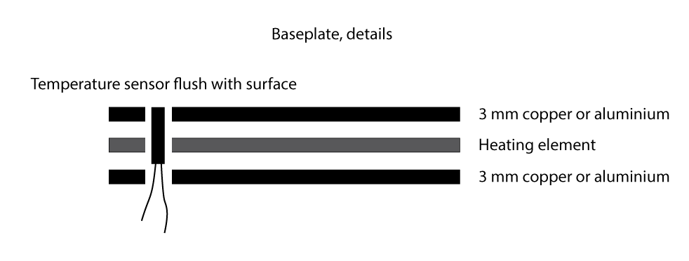
And a close up of the test plate
So what I need some help with is with component selection and creating a schematic for how to connect it all together. The system needs to keep the hot plate at a constant temperature according to the readings from the thermometers inserted in the hot plate. I know how to solder and how to put together basic wirings but this is over my head.



