Topic

MSR Whisperlite Universal flame control question (Roger Caffin please read)

  • This topic is empty.
Viewing 25 posts - 26 through 50 (of 51 total)
Roger Caffin BPL Member
PostedFeb 22, 2015 at 1:34 pm

> The newer pump valves have very little taper so essentially end up being an on/off
> and not a metering valve.
Not so. You can make a metering valve with almost zero taper if you want. Then it is the length of the needle in the hole, or the length of the restriction, which becomes thevariable factor.

Mind you trying to meter liquid fuel at ultra-low flow rates is a bit of a fool's game anyhow. Any bit of dirt in the orifice and … Which explains the Whisperlite International shaker jet thing.

A figure to remember: the liquid fuel expands into a vapour with an expansion ratio of about 250:1. That makes the liquid flow extremely small.

Cheers

Roger Caffin BPL Member
PostedFeb 22, 2015 at 2:35 pm

Hi Bob

Yes, I know quite a bit about micro metering valves – I was a research scientist for 40 years after all. But there are a few problems with them.

For a start, many of them are designed for very high pressures, something we do not have in a Whisperlite. In fact, running them at low pressure can be a serious technical problem.
Second, they are never light. They don't need to be.
Third, prices range from $60 to >$300 for fairly common small ones – more than the cost of a stove.
Fourth, none of them are designed to cope with potentially dirty fuel in the field. I used to vacuum micro-filter my kero, which usually avoided problems. For white gas you would have to pressure filter.

So yeah, there are possible solutions. But are they economic and practical ones? Opinions differ.

Cheers

Bob Gross BPL Member
PostedFeb 22, 2015 at 3:33 pm

If it is so difficult, then how does my inkjet printer's cartridges meter out 3 picoliter droplets? And, this is in a cartridge that costs $10.

–B.G.–

Roger Caffin BPL Member
PostedFeb 22, 2015 at 4:06 pm

Hi Bob

Understood. There are differences in the two applications. Forgive me if I go into lecture mode – force of habit.

The micro-metering valves are designed to provide a continuous flow at a certain rate. This could be something like 1 uL/min, but the flow might last an hour or a day. This is done by having a very small aperture and relying on standard fluid impedance theory – if anyone really understands the flow regime, which they don't. Often the flow through the hole is actually limited by obscure hydrodynamic factors as well, which is why they specify the valves for high-pressure use. But the flow is continuous. The rate then depends on the effective cross-section of the hole.

Yes, there are PhD theses and published research papers on how fluid flow through an orifice works. The maths is horrible.

The injet printer does not have continuous flow at all. It operates by 'drop on demand' instead. Typically it does this by exploiting some other physics. What happens is as follows.

First, the ink fills up a tiny chamber by capillary action. Obviously, the lining of the tubes carrying the ink must be wettable for this to happen. Then, when the printer wants one drop of ink, a tiny heater at the back of the tiny chamber glows for a microsecond or two, turning the immediately adjacent water in the ink into steam. That might be 1% of the ink volume in the tiny chamber. You will have seen all those gold-plated electrical contacts the the head of the printer: they are for the heaters.

The pressure inside the tiny chamber rockets up and the ink 'tries to escape'. Some of the ink does actually go back up the tube by which it came in, but that tube is very small so what escapes there is very little. The rest of the ink in the tiny chamber finds an escape via the small hole at the front of the chamber. Translation: a tiny drop of ink is spat out forwards, to hit the paper and be absorbed there. Now repeat 10 or 20 times in a vertical row, and at a kHz rate or more, and you have a B&W ink jet printer. Have 5 o6 columns of these holes and you have a colour ink jet printer. Yes, the print head is a marvel of modern micro-engineering – but if you want a million of them, technology can provide.

Why does the ink not dribble out of the holes at the front of the chamber? Surface tension keeps it in, just like with DWR-coated fabric. Obviously, the hole in a stove valve is much bigger.

HTH
Cheers

K P BPL Member
PostedFeb 22, 2015 at 4:31 pm

Reading through this thread for the first time in its entirety reminds me of watching the Big Bang Theory and listening to Sheldon explain some nuance of String Theory :)

K

Bob Gross BPL Member
PostedFeb 22, 2015 at 4:36 pm

Some day we may have a microcontroller metering fuel through a similar set of jets as the inkjet cartridge. Of course, then we will have to have a battery to power all of that, and then a user-control interface, and then …

Oh, the future is so exciting.

Professor Caffin, will this be on the final exam?

–B.G.–

Roger Caffin BPL Member
PostedFeb 22, 2015 at 4:49 pm

Hi Bob

> a microcontroller metering fuel through a similar set of jets as the inkjet cartridge
Actually, something similar has already been done, but for printing carpet tiles, not paper. An array of jets was used with a Coanda-effect 'valve' on each one, to spit micro-litre drops of ink onto carpet tiles. Yes, hundreds of Coanda-effect valves across a carpet tile. You needed that much ink to make the printing visible on the carpet pile, which absorbed a LOT of ink. Unfortunately drying the carpet tiles afterwards was a bit of a bottle neck.

The project was run by a fellow worker. I still have a lot of the print mechanism (in pieces) in my workshop. Maybe some of the bits will be useful one day?

You could however have custom-printed tiles, each one different. At one stage he was printing a different Playboy Bunny on each tile …

Why do I know all this? Because when ink jet printers were first being developed, companies like Hewlett Packard were only too happy to explain all about their wonderful technologies in their corporate science publications (eg Hewlett Packard Journal). But those hey-days of corporate research labs are long gone.

> Professor Caffin, will this be on the final exam?
We are plotting far worse than that for the future. You will have to pass the exam before you can buy a stove! Evil cackle follows …

Cheers

PostedFeb 23, 2015 at 11:51 am

Professor Caffin, we micro meter or perhaps milli meter liquid all the time. Slide carburetors are one good example. Measuring flow also is a matter of measuring the differential pressure across the orfice. The equation itself even is not hyper complex.
Yes, I agree that even with a flat orfice you can adjust the flow of liquid fuel however, for example, on the whisperlite the theoretical orfice size maximum is limited by the area of the eighth inch chord (used to pass liquid fuel to the feed hose) milled onto the side of the quarter inch valve stem thread which is a 1/4-32 thread. I haven't calculated that area yet. The stem moves out of the seat therefore at 1/32 inch per revolution. I would anticipate that the area open at the valve seat itself will equal the chord area within a fraction of a turn. A longer taper should stretch this out some.
As Roger said the density of the fuel is reduced by approximately 250 times on the way to the jet so the flow adjustment at the pump will need to be 250 times more sensitive than at the stove. Evidence of this is how the taper and size of the valve seat at the stove is on the Dragonfly. It looks very similar to the shaker cleaning needle.
So, what makes the new universal simmer so well. One post suggested it was the design of the vaporization tube which is bent slightly different than the older whisperlite international? The tank valve appears to be the same. The jet sizes are the same. I have added heat gathering material to the vaporization tube on the international which does help with low flame stability without lowering tank pressure but makes it difficult to disassemble the stove.
Did someone come up with a reasonable source for the hose fittings? I'm totally ready to make some pressure and flow measurements and perhaps construct a valve.
I like the microcontroller idea. Maybe we would pulse modulate the orfice. Some of TI's MSP series controllers could operate from the heat of the flame. All you would need to do is tap a button to switch fuels and flame strength.
Thanks for the memories. I still have some old HP Journals lying about. Also on the injet stories. I have worked with Video Jet in the past. It used electrostatic fields to form drops that it planted on the sides of jars and bags sometimes a foot away. I used microscopy and strobes to view the individual drops, adjust the high voltage fields so they were spherical. Pretty messy sometimes.

Roger Caffin BPL Member
PostedFeb 23, 2015 at 1:07 pm

Hi Bryant

> The equation itself even is not hyper complex.
That's the engineering version. Try to calculate the pressure drop across a small orifice from first principles (ie laws of physics) withOUT invoking any arbitrary constants. Could be another hundred years before we can do that.

For what it is worth:
I don't believe the design of the pump has anything to do with simmering.
Talk of fuel/air pumps is just wrong: they all pump just fuel.
I don't believe the design of the preheat tube on the Whisperlite has much to do with simmering either.
I DO believe the design of the needle valve is responsible for maybe 90% of the ability (or lack thereof) to simmer. There is more to the design than just the cross-section: there is also the length of the taper in the hole. A one hundred square micron hole in a thin plate (the classical orifice plate) has a different impedance to a length of tubing with a one hundred square micron bore.

Coleman used to have a competent stove designer, but I am not sure he is there any more – since Coleman was bought out. Some of the designs they have come up with in recnet years are just wierd! They came, and they went. Ever tried using a Denali?

Posting URLs for technical stove discussions is ALWAYS permitted! :-)

Cheers

PS:
> I used microscopy and strobes to view the individual drops, adjust the high
> voltage fields so they were spherical. Pretty messy sometimes.
We found that the secondaries were the real mess. They were smaller, so they went … elsewhere.

Stuart R BPL Member
PostedFeb 23, 2015 at 1:36 pm

What else meters a low flow rate of fuel under low pressure?
How about the idle valve on a RC model engine (10cc or less).
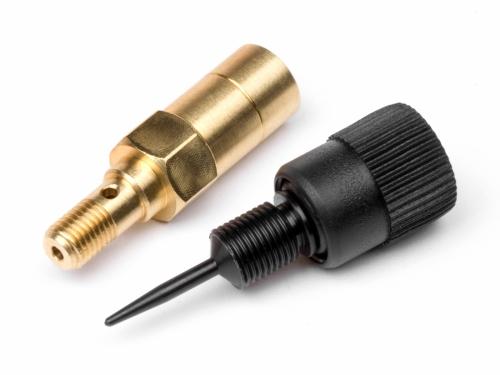
It can be done. I use one of these on my inverted canister stove.

needle valve set

Roger Caffin BPL Member
PostedFeb 23, 2015 at 2:01 pm

Hi Stuart

Good photo – an excellent illustration of what I was saying. See that long tapered section on the tip of the needle? You poke that into a long hole and it creates a long tapered restriction. You undo the needle one turn and the impedance does not change all that much because of the long 'tube' the needle creates inside the brass holder. It's not a thin orifice plate; it's a long tapered tube in effect.

At another level – hum, needle valves for model aero engines eh? I must investigate. Am I right in thinking that the needle is actually plastic? That could be a limitation.

Cheers

PostedFeb 23, 2015 at 2:23 pm

I have a pre-shaker international and it doesn't really simmer. I can make it simmer by constantly adjusting it, and sometimes relighting it. Not would I would call "simmerable".

PostedFeb 23, 2015 at 3:45 pm

Roger, I concur, the derivation of that formula is for sure a complex exercise in fluid dynamics. Straight away, I am unsure of the fluid control dynamics of a long tapered needle in a fitted tube vs a long tapered through a orfice plate however I can imagine increased eddie flow (especially in a non-steady state condition) and component wear with the plate. Perhaps this is why MSR added the spiral groove to the very end. But that long taper will allow finer control per revolution even even though a plate. On the new pump valves it appears that the hole that the end is more of a short tube where the (slightly tapered end pin with a spiraling grooved ) seats. It's really difficult to see. The older pumps appear to have just a hole through a plastic plate. And the older pumps had valve stems with a bit longer taper. I also remember seeing an MSR valve stem that was red plastic that had a long taper.

Thanks Larry, I have no experience with the older preshaker stoves. I only read references to them.

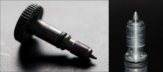
I am also uncertain where the whisperlite and Simmerlite valves actually seat. I looked around for some hi-spot blue to determine this. My first assumption was that it seated at the small maybe 2 mm taper at the end however a gentleman in Europe filed down the taper on an older whisperlite with an aluminum stem and control for simmering happened. The pictures he posted were unclear and I am awaiting to hear from him. His description sounded like he tapered the stem just forward the 1/4 inch thread.Modded stem

Roger Caffin BPL Member
PostedFeb 23, 2015 at 4:13 pm

Hi Bryant

Yeah, complex. Experts in hydrodynamics do not expect a solution anytime soon. There's a joke about an elderly physicist who was asked what he hoped to find out in heaven. He replied that chaos theory and hydrodynamics were two great mysteries, and that he had some hopes about chaos theory. The pictures are simple, but the maths are not.

The reason that a long pin in a long hole behaves differently from any pin in a thin plate is the boundary layer effect. The flow of gas or liquid (ie velocity) at the surface of the hole (and the needle) is essentially zero. The volocity ramps up to the middle between the two surfaces. When you have a long hole with a tapered pin in it, there is so much more surface area and boundary effect. That translates into drag, or impedance.

Micro-metering (which Bob raised) is normally reserved for very high pressure situations, when the pressures involved force the boundary layer to be very thin. We are not dealing with high pressures here. That said, the difference is really just one of degree.

Where do the Whisperlite valves seat? I don't know. The parallel shaft behind the tapered tip in your photos suggests that the actual shut-off may be back at the 1/4" diameter region. This makes for very poor control at low flows (of course), but does make for a more robust valve. I imagine the liquid fuel stove vendors are far more concerned about getting a hard shut-off for liability reasons. So if you tapered the 1/4" shaft bit slightly you might get slightly better control,but it might be a bit more open to wear just there.

As far as I can see from examination of a reasonable number of canister stove valves, the needle tapers back to the bigger threaded region (or to the O-ring groove) in such a manner that the shut-off has to be happening at the root of the taper, not any further back. You might expect that this could damage the valve seat at the edge of the hole over time – in fact it may reshape it slightly. But since the needle valve is still tapered there, a small amount of flattening at the rim or edge of the needle valve hole does not matter. Do up the screw another 10 degrees and it will seal just how it should.

While I used a commercial needle valve in my Winter Stoves, I machined the valve seat myself, and that is how I managed to get nice fine control.

Cheers

PostedFeb 23, 2015 at 4:41 pm

Great description Roger, thanks
Do you think the impedance/friction at the boundaries exceeds the impedance that the restriction (orfice) presents to the system or is it a component of the orfice itself?
T
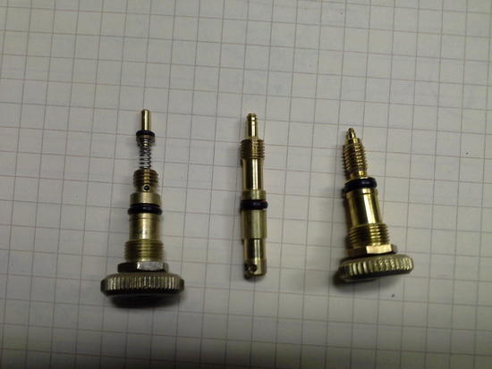
Below is a pix of 3 valves I'm investigating. The one on the right is from the Dragonfly pump, the middle valve stem is from a newer pump, the one on the right is from the Simmerlite.

The Dragonfly pump valve exhibits seemingly no simmer control on any stove. The new pump valve has very little simmer control (less than 2 minutes of arc). The Simmerlite valve will provide almost 30 minutes of arc (½ turn).MSR valve stems

Roger Caffin BPL Member
PostedFeb 23, 2015 at 5:16 pm

> is it a component of the orfice itself?
Um. Which is the greater – the boundary layer effect or the size of the hole?
I don't know.
I suspect that at very low flows the boundary layer may be more significant, but I don't know.

> The one on the right is from the Dragonfly pump, the middle valve stem is from a
> newer pump, the one on the right is from the Simmerlite.
Typo – you have labelled both 'on the right'.

I have never seen a valve which uses a spring-loaded needle plus an O-ring on the needle itself. Guessing wildly, I suspect that the fuel flow is against the spring? And that doing up the valve loads the spring so the O-ring shuts off the flow. How well that works in practice … how much dirt is in the fuel?

The so-called regulators on a few stoves like the SOTO do use springs, but somewhat differently. What stove is the spring valve off????

Cheers

PostedFeb 23, 2015 at 6:32 pm

Oh my, the center one (without a handle in the pix) is the newest pump valve. So there are 4 to look at now with the possibility of another if I fin a pix of the plastic one. I will retake the pix to be able to see the profile better.

Here is the preferred fluid boundry condition to undertake.BWCA

PostedFeb 23, 2015 at 6:39 pm

That spring loaded seat with the o-ring seal I presume is the regulator mechanism Eric was referring to earlier. I suspect that there is something going on there. We have nearly all the components of a pressure regulator. Maybe not under all conditions though. I would like to measure some pressures once the Dragonfly reached a steady state. I have a small can of swaglock fittings and some tubing and am eying the possibilies.

PostedFeb 23, 2015 at 6:55 pm

Whoops, the spring loaded seat valve is from the Dragonfly. I don't know if was utilized on other stoves from that time period.

Roger Caffin BPL Member
PostedFeb 23, 2015 at 7:56 pm

Hi Bryant

> The Simmerlite valve will provide almost 30 minutes of arc (½ turn).
Um – I think you mean 180 degrees of arc? 30 minutes is half a degree.

> The Dragonfly pump valve exhibits seemingly no simmer control on any stove.
Odd. The design is clearly meant to provide some pressure regulation, but if it doesn't then maybe we have a disconnect between the theory designer and the factory making. No feeedback or factory involvement by the designer, or maybe he was a fresh young hire (ie cheap) with very little experience.

And when the stoves coming back from the factory did not 'pressure regulate' they were meant to, the company just shut up about it. Unfortunately I find it very easy to believe that of the current company, going on their more recent acts. They seem to be long on lawyers but short on talent.

Such a passive design will never achieve perfect regulation; it would be struggling to achieve 'good' regulation. But no regulation – sad.

Cheers

PostedFeb 23, 2015 at 9:07 pm

Yup, polarly, would that br an order of magnitude? Oops

Perhaps it comes to play only under certain conditions.??? Maybe as a flow/flame stabilizer at low tank pressures. I'll have to think about what it will take to put that spring into a ½ compressed range. Maybe low tank pressure and simmering and the tubing gets hot.

It was/is a sad time when most if not all engineering and design decisions became fiscal.

Bob Gross BPL Member
PostedFeb 23, 2015 at 9:39 pm

Larry Penberthy must be rolling over in his grave.

He was probably the original Stovie.

–B.G.–

Viewing 25 posts - 26 through 50 (of 51 total)
Loading...