Topic

What size CF tube to match alum tube strength?


Forum Posting

A Membership is required to post in the forums. Login or become a member to post in the member forums!

Home Forums Gear Forums Make Your Own Gear What size CF tube to match alum tube strength?

Viewing 13 posts - 26 through 38 (of 38 total)
  • Author
    Posts
  • #3517401
    Paul French
    BPL Member

    @ssghawk

    Locale: Northern Texas

    Sam and Daryl,
    Thanks for great insight, experience and comments.I has been a blast.

    Can you please take a look at the following picture and give me your opinion on the thickness and height of these aluminum wing arms?

    Sam,
    Thanks for great insight, experience and comments.I has been a blast.

    Can you please take a look at the following picture and give me your opinion on the thickness and height of these aluminum wing arms?
    Regards,
    Paul

    I am going to try to make my JackPack clone out of Easdton .490 that gas .438 ID that will allow use of Daryl’s  3/8″ plastic tees.

    Do you think that I could eliminate the middle vertical in Jack’s design by reinforcing the bottom horizontal where the the back of the waste belt attaches?

    Did you ever weight and of the original JackPack tubing to determine its weight per inch?

    Regards,
    Paul

    #3517411
    Roger Caffin
    BPL Member

    @rcaffin

    Locale: Wollemi & Kosciusko NPs, Europe

    The devil is indeed in the details.

    This is my winter pack; my summer pack is very similar. 3 month long trips in Europe and extended XC ski touring.

    The core of the pack is the (Easton arrow) tubular frame. It has a LenoLock mesh panel strung tightly across it, to give strength to the frame and to allow air to circulate past my back. You can see string zigzagging behind the mesh: that is what keeps it tight.

    The frame itself consists of two straight uprights – probably 355 size, and 5 curved cross pieces – a smaller size. The curve goes across my back. I use a bending machine to get the curves.

    The junctions are the devil bit. The brackets are pressed aluminium, pop-riveted together  and secured to the tubes with Loctite Black Max superglue. The ones at the bottom are shown here.

    There is a slot in the bottom side of the bracket for webbing for the shoulder straps. A loop of webbing goes through the slot and is retained by a short length of whipper snipper cord.

    Do NOT, under ANY circumstance, EVER loop the webbing around the cross bar. I did at the start, and it tore the cross bar out of the bracket. Many times, in the Pyrenees. Rather embarrassing at the time, but Sue put up with the time for repairs until I figured it out and fixed it – in the field.

    For the middle cross bars I used a smaller bracket:

    Mainly because it was lighter. On that score, note that I also punched all the steel ‘nail heads’ out of the pop rivets. Two reasons: rust and weight.

    The shoulder straps are supported by the 2nd cross bar from the top, PLUS by the load lifters from the pack bag. I do not put all the load on the cross bar! The two shoulder straps interlock as well.

    One strap comes up from the nearest corner, goes behind the frame, and down to the other corner, where it is anchored and forms the lower part of the other strap. Some thinking needed.

    Of course, the big question is where did I get the brackets from? You can’t buy them. I made up two forming dies out of steel to match the two sizes of Easton tubing. Yeah, a few months work as I did not have the CNC then.

    The red fabric is Dimension Polyant VX07 for the bag and black VX42 for the base. The shoulder straps are also VX42 (or heavier?). I added some felt shoulder pads later. Yeah – 1/2″ wool FELT. It has outlasted all the CCFs you can think of.

    Cheers

    EDIT: the hip belt – a nominal thing to stop the pack slewing around when scrambling or skiing. I don’t think it carries any significant amount of weight. The main load is carried by the mesh on my back. The shoulder straps help of course, but are definitely NOT the main connection.


    #3517460
    Daryl and Daryl
    BPL Member

    @lyrad1

    Locale: Pacific Northwest, USA, Earth

    Paul,

    “Can you please take a look at the following picture and give me your opinion on the thickness and height of these aluminum wing arms?”

    Took a look at photo.  No experience with wing arms.  No help with determining best thickness and height of wing arms.

    Daryl


    #3517465
    Paul French
    BPL Member

    @ssghawk

    Locale: Northern Texas

    Roger,

    Simply beautiful.

    <span style=”text-decoration: underline;”>How Not to Destroy the Top Bar(s</span>)

    “One strap comes up from the nearest corner, goes behind the frame, and down to the other corner, where it is anchored and forms the lower part of the other strap. Some thinking needed.”

    So the top bar carries no significant weight since any weight related to the shoulder straps is really carried by the lowest bracket on each bottom corner where the shoulder straps are connected? Other weight is carried by the mesh against the back. Correct ?

    <span style=”text-decoration: underline;”>Material specs</span>.

    What was the approximate thickness of the aluminum(?) used in the brackets?

    <span style=”text-decoration: underline;”>Shade Tree Mechanic Bracket Dies and Forming Press</span>

    Possibly over agreesive in my thinking but, subject to the material type and thickness,I probably could use two pieces of say 4″ long 355 tubing filled with sand/cement /something that won’t crush as part of the dies. Probably could make the top die out of oak easily, but very rougjly shapped with wood working power tools.Bottom dies would be a flat surface (Loctite Black Max superglue ultimately will fill any gaps when assembled). Then a manually pumped hydralic shop press (or maybe even a king kong bench vise) might just form the brackets. Not elegant and with lage tolerences but should do the job when on the frame?

    <span style=”text-decoration: underline;”>Curving the Horizontals</span>

    ” I use a bending machine to get the curves.”

    Are you talking about this type of machine?

    Central Machinery® 38470 Compact Bender

    Back to a shade free approach. Could they be bent manually as per this YouTube. (I know definately not professional and the separate curved poles will not match):

    YouTube video

    Do you see any fallacies here?


    #3517520
    Roger Caffin
    BPL Member

    @rcaffin

    Locale: Wollemi & Kosciusko NPs, Europe

    So the top bar carries no significant weight since any weight related to the shoulder straps is really carried by the lowest bracket on each bottom corner where the shoulder straps are connected? Other weight is carried by the mesh against the back. Correct ?
    Correct.

    .Bottom dies would be a flat surface (Loctite Black Max superglue ultimately will fill any gaps when assembled).
    I doubt that the flat bottom would work well enough. The gaps would probably be too big for a superglue. I made a symmetrical die. But … one could try.

    Are you talking about this type of machine?
    No. Custom rolling bender. MYOG.

    Very controlled curvature and very repeatable. Counted turns of the adjustment screw (3.75 from memory).

    The packed sand (salt, sugar, whatever) plus knees approach will probably fail with the 7075 E9 tubing. Too much force needed – uncontrolled.

    Ch

    #3517552
    Paul French
    BPL Member

    @ssghawk

    Locale: Northern Texas

    Roger,

    Custom rolling bender. MYOG. Very cool.

    I was a motor pool Sgt in the military and I worked my way through college as a manufacturing plant engineer (fancy term for machine repair and rebuilding mechanic). So I have the skills to build this but I no longer have a shop as I switched into forensic accounting 25 years ago. A bigger problem is how I build one of these without the wife knowing.

    Where there is a will…………

    #3517591
    Roger Caffin
    BPL Member

    @rcaffin

    Locale: Wollemi & Kosciusko NPs, Europe

    A bigger problem is how I build one of these without the wife knowing.
    That, Sir, is entirely YOUR problem!!!!
    You could (maybe) tell her that you cannot justify the cost of a fancy new pack (much $$) no matter how much you need one, so you are going to MYOG instead with a huge cost saving.

    Where there is a will
    There are usually a lot of hungry relatives and their lawyers.

    Cheers

    #3517615
    Sam Farrington
    BPL Member

    @scfhome

    Locale: Chocorua NH, USA

    Thanks, Roger, for the review of your pack design, materials and construction.

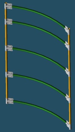
    RE:  Paul’s request:  “Can you please take a look at the following picture and give me your opinion on the thickness and height of these aluminum wing arms?”

    Would suggest building the frame first to make sure it will work with and fit the body, before deciding on the dimensions of the pack.

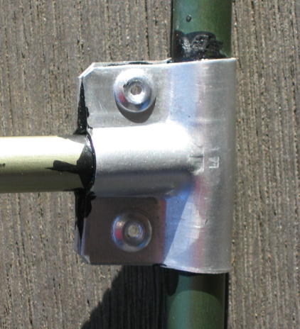
    If those sidearm bars are ALU alloy as they appear to be, they will flex out of shape.  Any flex in the sidearms will make it impossible for the sidearms to hold the belt snugly to the hips.  That is why Jack S used two tempered ALU tubes for each arm.  I don’t recall, but think they were highly tempered Easton  5/8″ OD tube.  That is also why I decided to use two tubes for each arm taken from tempered X-C ski pole ends, tapering from just below 5/8″ OD to about 3/8″ at the baskets.  Of course, with a hipbelt strap and buckle installed, the sidearms will not flex further open, and Jack S did install those on his sidearms.  But I got away from front buckles altogether, and to do that, the tips of the sidearms cannot be allowed to flex further open from the position to which they are adjusrted and set; that is, they as well as the crossbar tubes must be rigid to maintain a constant position and distance between the sidearm points.

    I tried using Easton .340 tempered tent tube for the sidearms.  It is plenty rigid, but I was worried about the abuse it might sustain sticking out from the pack.  I will use highly tempered tent tube, however, for the crossbar tubes on the frame above and below the hipbelt.  If it flexes, however, a more rigid material will have to be substituted.

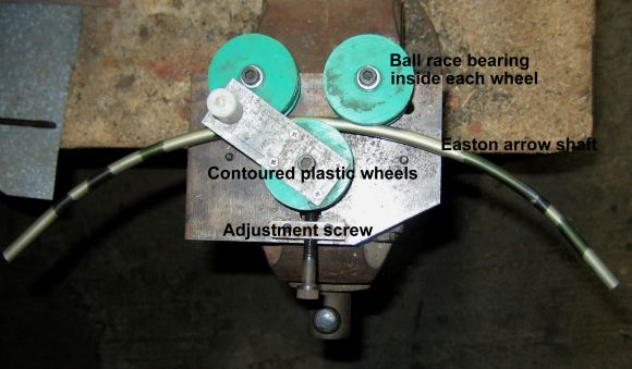
    Many thanks again to Roger for bending some Easton .340 tube for me a few years ago on his home made device pictured in a post above.  I have found that with sand I can bend that tube about half as much as Roger’s device can; that is, with around twice the radius for the bend.  The sand must be fine, tightly packed, the tube ends capped before bending, and the temperature well above 70 degrees F for at least a day.  The tubes were cut longer for bending, placed at a right angle to and over a the side at the bottom of a large diameter soft plastic construction bucket laid on its side.  Grasping each end with gloves, I sat on a stool and leaned over the curve of the bucket, bending just a little at each of many points on the desired curve.  It worked fine except for a few botched tubes.  But Roger’s bends with his device are much more precise.  Doubt that I could do that today with the back issues, so glad that I have two sets of curved tubes now to work with.  To bend the X-C ski pole pieces, will use a 3″ radius Ridgid brand 5/8″ tube bender bought as a kid for a fraction of what they sell for today.  But as with the bucket bending, just a little bit of bend at multiple points in order a get as close to a continuous curve as possible, and the sand etc.

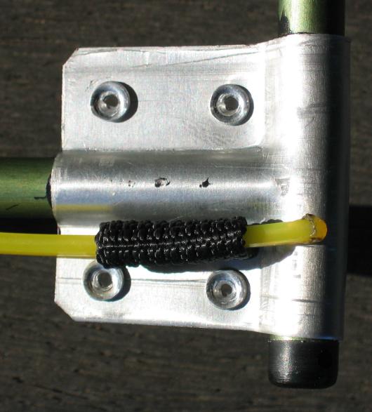
    As with Daryl’s KISS pack, the Tees I plan to use are made from hose barbs, and are very rugged nylon branded ‘WATT’ and sold in the big box stores.  They are bored to the desired ID, with most of the barbed sections cut off and buffed.

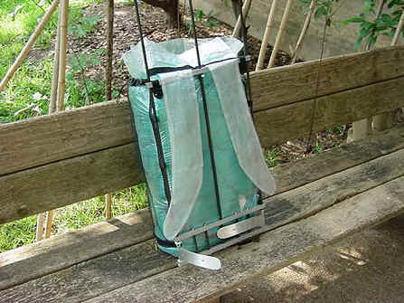
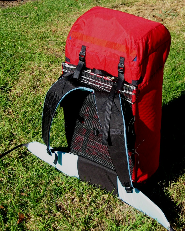
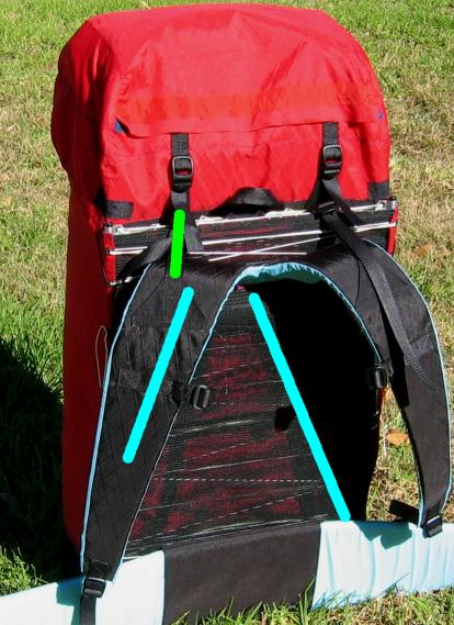
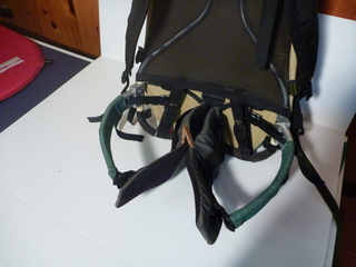
    Did you mean thickness and Width of the bars?  The height of the wings vis-a-vis the ground varies from the frame to the points.  However, the higher the sidearms can be placed on the pack, the less the top of the pack will tend to roll from side to side.  The next pack will have the wings set higher than the one shown in the earlier post.  Also, here is a photo of that pack with the belt pushed away to give an idea of what lies behind it:

    Apologies to those who have read all this before, but with posters constantly coming and going on BPL, repetition is often needed, so I’ve come to accept the ‘Groundhog Day’ character of these MYOG threads.

    #3518011
    Paul French
    BPL Member

    @ssghawk

    Locale: Northern Texas

    Roger,

    “………..and their lawyers.”

    A recent study in the US indicated that approximately 40% of last year’s graduating lawyers are not working as lawyers or or working at legal positions earning after tax wages that barely cover their law school student loans.  So the competion for any case even on a contingency compensation basis is  fierce.


    Sam,

    “The tubes were cut longer for bending, placed at a right angle to and over a the side at the bottom of a large diameter soft plastic construction bucket laid on its side.”

    In the military we had to do alot of things like that. Never pretty, but we kept things running.

    Not wanting to be embarrased with pictures of my completed product with the curved sections all with obviously different curves (and not wanting to spend $180 at Harbor freight for the proper Roller machine) I am thinking about buying the 135(?) degree “Aluminium Alloy Connector Angled Pole ”

    like this:

    Camping-4-Pcs-Aluminium-Alloy-Connector-Angled-Pole-for-13mm-Tent-Pole

    $19 delivered for 4pieces in 13 mm and then Locktight Black max.

    “If those sidearm bars are ALU alloy as they appear to be, they will flex out of shape.”

    I am thinking of using the thickest aluminum that I can bend around to make the hinge part that will rotate around frame vertical.(Bend around as in a 3 lb sledge and a large vise.) Once around the vertical, the piece will be Locktighted and riveted to itself. If I get too much flex it will probably mean that the arm needs to be taller (something like a 3/16′ thickness by 3.5 or 4″ tall rather than 3/16′ thickness by 2.5″ tall) Possibly I will layup a couple layers of carbon fiber to add strength. Bill Fornshell made the frame with the aluminum arm that I had in my post above and based upon everything he wrote I would guess that his aluminum wing arm was probably workable or at least very close to workable. You have obviously proven that your design without a belt buckle works but I like the stability of the tight buckel.

    “here is a photo of that pack with the belt pushed away to give an idea of what lies behind it:”

    That picture was very helpful. Man, you did one heck of a lot of tube bending. It looks perfect.


    Great stuff gentlemen.


    #3518116
    Sam Farrington
    BPL Member

    @scfhome

    Locale: Chocorua NH, USA

    Paul,

    I guess we agree that if you are going to use an adjustable front buckle, there is no need for a rigid closure around the hips.  However, if you still want the benefit of sidearms, they will have to attach to the frame so that they are rigid vertically, if not horizontally,   Saying that the wings are ‘hinged’ suggests this, so this comment is just to add emphasis.  For example, If you look at some of the latest iterations of Osprey packs, hidden underneath the hip belt covers are mechanics that prevent the hipbelt and buckle from rotating up at the front.  Not going to spend $$$ to buy and cut open an Osprey to see the mechanics, especially since did not find them very comfortable when trying out at EMS.  But the idea is to prevent the pack from slipping downward, and pulling at the front of the belly, which is the curse of conventional packs.  Maybe not a problem for those with six-pack abs, but desk soldiers also like to backpack.  Found that it could be done, but only if there is a fixed rigid approx. right angle between the pack frame (vertical) and the hipbelt (horizontal).  Jack’s pack frame is one way to do this, along with other benefits discussed earlier in this thread.

    The reason for using tubes for the sidearms is based on the idea that a girder will be much more rigid than a bar.  Tubing is the simplest way to apply this.  Not surprising that pack frames have been made of tubing since the Kelty era began.

    Also, except for the three points of hipbelt attachment, at the small of the back and at the two sidearm points, there must be some daylight between sidearms or wings and the hipbelt.  This is critical to allowing the belt to move without abrading it, and your hips as well.  Insufficient separation here was an issue with my earliest prototypes and it had to be fixed.  Likewise, the sidearms must project just enough distance forward that their points cannot force the hipbelt to press and rub against the body.

    So to sum up, the wings cannot be floppy, at least vertically, and they cannot cradle the hips too closely,as there must be a significant degree of separation to allow hip movement.

    As for bending tubes, grinding a telescope mirror as a teen taught me that doing things in small increments can produce incredibly accurate results.  When the frame project is done, I intend to include a photo of a number of Easton .340 tent tubes, prebent to curves and arranged in or around an hourglass shape.  That should add some clarity and show that the curves can be consistent.

    #3518130
    Daryl and Daryl
    BPL Member

    @lyrad1

    Locale: Pacific Northwest, USA, Earth

    http://www.oregonphotos.com/Warmlite2.html#anchor4337

    This has been posted before but a fresh look might remind people what the Jack Pack looked like.

    #3518164
    Paul French
    BPL Member

    @ssghawk

    Locale: Northern Texas

    Sam,

    Good points.

    “grinding a telescope mirror as a teen

    Very impressive. I am pretty sure that with a detailed instruction book and the right tools even now, I would probably destroy 2 or 3 such mirrors before I got one right.

    I have two of the JackPacks (not in front of me at the moment as I am at the offfice) that have two about 5/8″ tubes about 2″ apart as the upper and lower portion of each Wing arm. (Different than the original wind arms included in Daryl’s picture.) I am trying to duplicate the JackPacks that I have as much as possible, but lighter weight. Those 2 Wing arm on my real JackPack attach to the vertical with a fitting that probably was special made for Jack. I think I possibly could make a fitting like that as I have a welder somewhere but any fitting I make will be heavier than what is on my JackPack.

    I follow your comment concerning how the wing arm must be attached to the vertical and you have convinced me to start with a 3/16′ thickness by 3.5 or 4″ tall aluminun wing arm. The entire 3.5 or 4″ will be wrapped around the vertical thus transfering the weight over that 3.5 or 4″ area. This will be one of the most critical stress points and I might just test it and a vertical to the point of destruction just for kicks.

    I also am trying to size my verticals so that I can slip a resonable tolerence smaller OD inside the main vertical (and Black Locktight it) at least for the bottom foot to further strengthen the vertical where the hinge is wrapped around and 6″ or so above that point.

    I do not yet have weight ionformation for these components and the weight may exceed the weight of my jackPack which would be a non-starter. Time will tell.


    and they cannot cradle the hips too closely,as there must be a significant degree of separation to allow hip movement.

    Good catch. Another thing that I had not thought of. I will have to study my JackPack and see how Jack solves that problem.


    Thanks again for the great ideas that are preventing me from recreating the wheel.

    Regards


    #3518280
    Sam Farrington
    BPL Member

    @scfhome

    Locale: Chocorua NH, USA

    Daryl and Paul,

    That earlier picture is one of Jack’s prototypes.  There were others pictured in other catalogs, but the one shown in my earlier post is the one that was sold for years until Easton, the supplier of the fittings, stopped making them in the smaller quantities Warmlite needed for sales, and the pack was discontinued.  I’ve lived not far from Jack’s NH shop and home for years, have made appointments to buy DYI parts and materials, and this is what they’ve told me when visiting.

    Paul, I was trying to be clear, but think I may have just complicated matters.  I would not use the metal bars for the reasons stated earlier; but if you do, they must be hinged somehow to the almost vertical tubes at each side of the bottom of Jack’s ladder frame.  That’s clear in Daryl’s picture of the older prototype also.

    I won’t harp about pictures, as I’m in the middle of the project myself, and have nothing new completed to photograph at this point.  So I apologize for perhaps getting too deep into the details without being able to provide pictures yet.  When more progress is made, I’ll post some pictures of the new project on a new thread, as all that is a stretch away from this thread.  Best wishes for success.

Viewing 13 posts - 26 through 38 (of 38 total)
  • You must be logged in to reply to this topic.
Forum Posting

A Membership is required to post in the forums. Login or become a member to post in the member forums!

Get the Newsletter

Get our free Handbook and Receive our weekly newsletter to see what's new at Backpacking Light!

Gear Research & Discovery Tools


Loading...