Testing the Burner
Having covered various technical details, let’s jump to some testing on the bench. Testing means making up a prototype or two. I had done so, even if they were a bit rough around the edges. Testing usually means further modifications, to cover up the revealed defects.

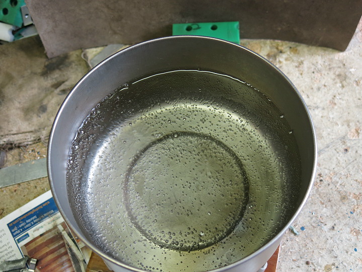
Bubble testing (V2) stove body
Experimenting is so much fun, as long as I had first checked for unexpected leaks using a water bath. Stray bubbles are not welcome: they tend to lead to little flames, and little flames lead to – well, problems. (This is bubble testing the V2 stove; the V2 stove body is longer. But I had the photo.)
I knew what area of air inlet I needed to get the fuel/air ratio right, but sometimes during early testing the flame would not come out of the burner chamber after I lit the stove. The flame stayed down inside, roaring away. With all the flame inside, the burner chamber naturally got very hot, very quickly: this could be dangerous stuff. Looking carefully in the short time available before I turned the stove off, it seemed that the flames were not forming a vortex. Turning the stove up in power did not work. So I turned it down, right down.
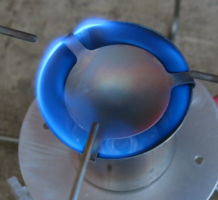
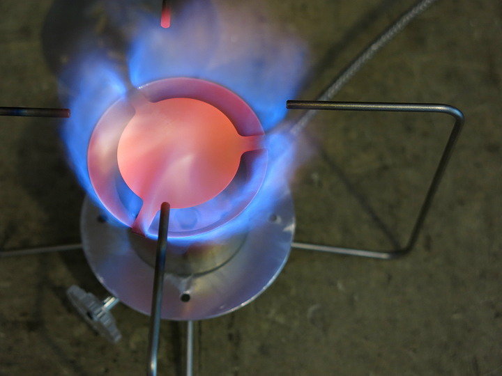
A low (but controlled and stable) flame coming out of burner
Eventually, at very low power, with a somewhat low volume of air being sucked in by the very slow jet stream, the flame went quiet and suddenly ‘popped’ out at the top. That apparently established the required vortex pattern inside, and I could turn the stove up to full power without worries. This ‘popping out’ was very reliable. Strange are the ways of gas dynamics in very small volumes.
I am going to classify this turning-down bit as part of the priming cycle. You start at LOW power till the burner chamber warms up and the flame pops out the top, then you slowly increase the power. In practice we are talking about the first 10 seconds to get the flame established. Since priming the whole stove for liquid feed takes a bit longer, this slow start does not matter. In practice in the field I have not even noticed the delay: I just start at low power and put the pot straight on. Why waste gas?
Let me add something here about priming. One of my V2 customers was having all sorts of problems with flaring when changing to liquid feed – and yet he had waited a full minute before inverting the canister. It was not until he sent me a video of his whole lighting cycle that I worked out what the problem was. He was starting with the stove going flat out, in the hope of reducing the priming time, but it does not work that way. The high rate of fuel flow was bringing in a very large quantity of liquid fuel to be evaporated (cooling the stove body), and the high air flow through the stove base plate was very effectively cooling the stove base plate. So liquid fuel was coming out the jet and flaring. The flames, being way up in the air, were not even heating up the burner chamber. I dare say the stove would have sorted itself out in due course, but it would have used a lot of fuel in doing so, and generated a certain excess of excitement.
I explained this to him and got him to try starting and priming the stove at LOW power. Half an hour later he emailed me to say ‘success’. Great was everyone’s joy.
Design all done – yes? Not quite, there are a few extra ‘minor’ details to deal with before we get onto testing.
Needle Valve Internals
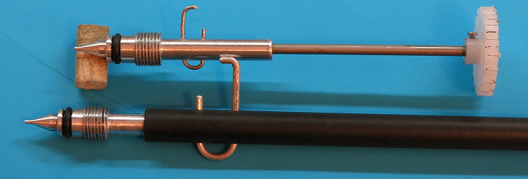
In a word: a short shank. But there is always the question of whether to put the O-ring inside, between the tip and the thread, or to put the thread inside between the tip and the O-ring. The complication is that the outside diameter of the O-ring must be less than the inside diameter of the thread, to avoid damage to the O-ring surface during assembly and cleaning. The two choices are illustrated below, although the top needle valve is missing the O-ring in the big groove. Ignore the bits of wire sticking out at the sides: I will explain them shortly.
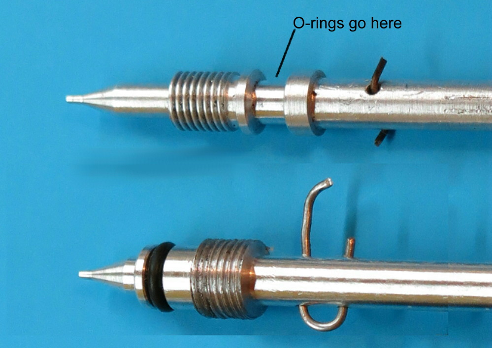
Needle valves with O-rings before and after threaded section</p>
I decided to put the O-ring inside, leaving the thread outside away from the fuel. This is a common approach used on many commercial stoves. So the lower needle (with O-ring) is the current design. There is a fraction of a millimetre clearance for the O-ring as it goes in, but that is enough to prevent the threads from damaging theO-ring. The design of the tip was discussed previously.
Needle Valve Handle
Basic minimal handle, a bit close to the flames
Let us jump forward to having a functioning stove on the bench. All very fine, but it turned out that the small control knob (clear plastic, bottom left) was very close to the burner chamber, and that burner chamber can glow red at times. If I left my fingers on the control knob for any long length of time the radiation started to make my fingers a bit hot! The knob could cope with the heat as the material is rated to 120 C, but my fingers are not. I could make the aluminium handle much longer, but that would make packing the stove up difficult. A longer handle would not fit neatly in my cooking pot. Clearly, an extension handle could be useful.
Two different lock pins through handles
I could try to make the extension hinged, but that would have been rather complex. (Translation: I have yet to figure out a viable miniature hinged design of adequate strength.) Instead I looked at some alternatives shown here: a thin wire going inside the handle or a larger tube going on the outside of the handle.
Titanium Wire
For the first idea, that of a Ti wire going inside the handle, I could use a length of 2.4 mm Ti wire for the extension. This means I have to bore a hole in the handle after the rest of the needle has been machined, which was tricky but possible. I could use 0.7 – 1 mm stainless steel wire as a locking mechanism: again fully retained so it does not get lost of course. (Which explains the wires in a previous photo.) However, there were complications. I will illustrate some of them.
Drilling a 1 mm hole in hard 2.4 mm diameter Ti wire is not easy: the very fine drill tip on the small Ti wire tends to wander off-axis from the very curved surface of the Ti wire – and break. Or the drill bit jams in the hard Ti wire, flexes and shatters. Those fine drill bits are expensive (I only buy good branded drill bits). This made me hesitate. However, later on and after some experimental work, I was able to drill 1 mm holes in the Ti wire on the CNC on a ‘production’ basis, without breaking any bits. But first I explored some other ideas.
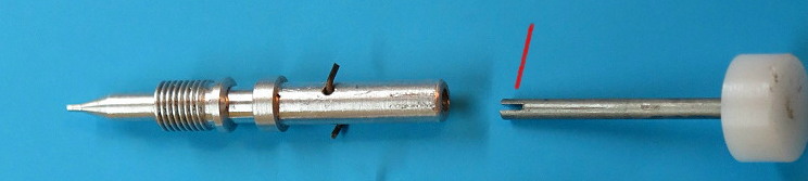
Slit Ti wire handle with mating section
Remembering how the handles on the Svea and Optimus 8R were made, I tried changing the connection at the end of the Ti wire to a simple slot, as indicated by the red line. Drilling the hole in the aluminium handle is not a problem: in comparison with the Ti wire the aluminium is ‘soft’. The slot in the Ti wire had to be cut with a good slitting saw. However, this too was problematic, as the slitting saw was very thin. Thin slitting saws can flutter and break. The slitting process turned out to be tricky as well: the slot tended to flare outwards so the Ti wire would not fit in the hole. I suspect the flaring is due to residual stress inside the wire from the drawing process. )
At this stage I had figured out what I thought I wanted for this approach: some sort of mechanism which would let me push the Ti wire into the hole and have it retained there. Nothing worse, so to speak, than having the control handle fall off the stove just when you need it most. (Oops – it’s flaring: turn it off quick.)
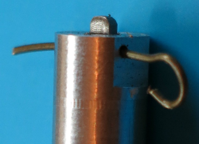
Close-up of spring clip, with Ti wire reversed to show flat
For my next bright idea I milled a flat at the end of the Ti wire (with a small carbide cutter) and put a spring wire through the aluminium handle a bit off-centre. The spring wire will stop the Ti wire from rotating inside the handle, and ideally keep it in place: it is a sort of key. The photo here shows a test unit which exposes the mechanism. The big aluminium rod is the valve handle, and the little bit sticking out at the top is the Ti wire with an indented flat on it. This is not a real valve, just a bit of a test unit. The dimensions are a bit critical if this is to work well, but the CNC can handle that. Machining this was easy, but the result did not work. Either the Ti wire would not engage with the spring wire, or it would fall back out too easily.
Several iterations of the design later I figured out the real problem and found a solution. The problem was that the short length of spring wire going through the hole has almost zero spring movement. I needed to have two sloppy holes, one on either side of the Ti wire, and a long loop of spring wire. By making the loop about 10 mm long I could adjust the tension satisfactorily, at least in the short term. Of course, there is no room for a 10 mm long loop sticking out of the handle, but this loop could be folded over to lie flush against the handle. It worked, with some tuning, but it had ceased to be an elegant solution – especially for the machinist.
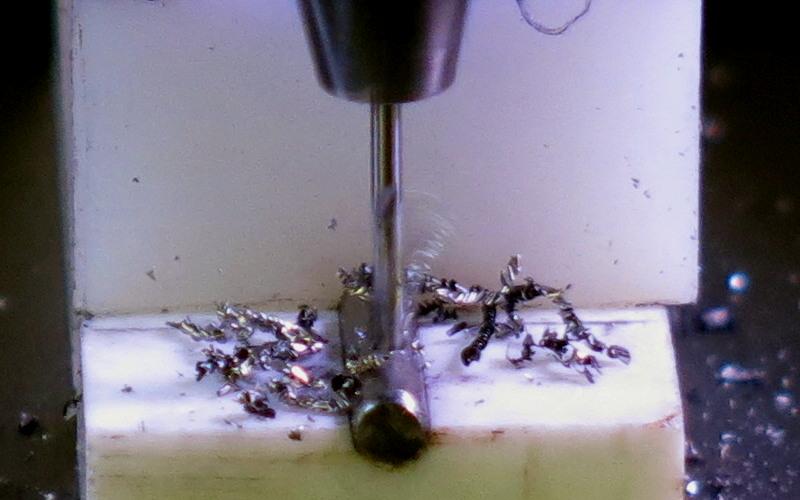
Drilling a 1 mm hole through 2.4 mm hard titanium
Later on I returned to the original locking pin idea. I was eventually able to ‘production-drill’ the hard Ti wire on the CNC without breaking drill bits. That’s a Swedish 1.0 mm drill bit there, although I have also used Swiss drill bits. So now I have some handles with spring clips and some handles with locking pins. This is pure showing off over the technology. But while this approach was possible, it was extremely delicate and fiddly. I won’t be making any more of them.
Tube Handles
For the second idea I had some choices: 7000-series aluminium tubing (Easton poles), Titanium tubing (in stock), and carbon fibre tubing left over from making up my CF tent poles. A 1 mm wire locking pin is indicated, although the photo below shows a somewhat ‘fat’ 1.6 mm Al wire pin I experimented with at the start.
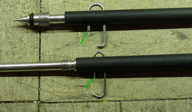
Carbon fibre tube handles with different lock pins
The idea is that the long arm of the U shaped bit of wire is retained in its hole by the bend at the end, while the shorter arm goes into a hole in the handle. With a tiny bit of tuning I can make the end of the wire (green arrows) stay just in the wall of the carbon fibre tube without blocking the insertion of the handle. That means the wire can’t fall out and be lost, and it will be (fairly) easy to get the wire into the matching hole in the aluminium handle. As far as a knob at the end of the CF tube goes, I found it was not needed. The surface of the CF tubing used was rough enough and large enough in diameter. I did not test the other materials as the CF tube worked fine.
A minor technical detail (yet again). If the hole for the lock wire is drill ever so slightly off centre, then trying to get the lock wire in the hole when the handle has been rotated 180 degrees is extremely difficult. Rather than sweating over the accuracy of alignment, I just redrilled the 1 mm hole through the handle to 1.5 mm. Problem solved – with the added benefit that it was now easier to get the lock pin in place with either rotation.
Comparison
I really did try the short aluminium handle as it is the simplest solution. but I burnt the hairs off my fingers a couple of times in the field. No (significant) damage done, but clearly not a good solution.
The Ti wire handle looks awfully neat, but it is a pain to make. The Ti wire itself is too thin to be reliably gripped, especially at -10 C, so a knob of some sort is required. The knobs shown in the photos are essentially the same as I have previously used on the V2 stove, but a shade smaller. Alternately one could have a loop at the end of the wire. The two choices actually work out at about the same weight. But in the field I found I was not happy about the hassles of finding the extension handle and fitting it. Others may differ – and I do have a few Ti wire handles available.
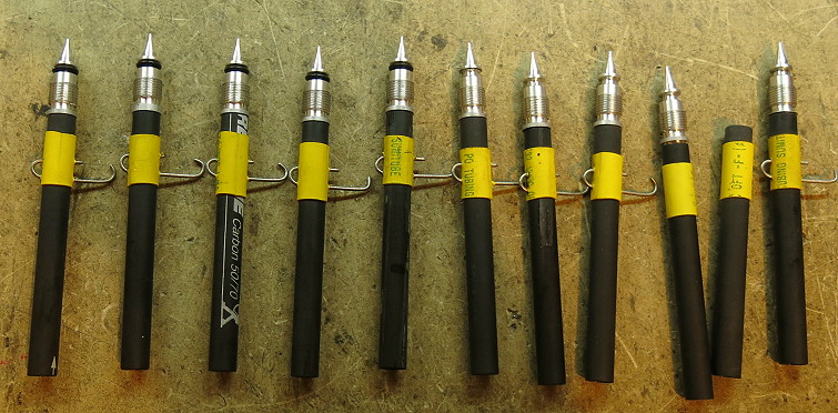
An array of finished needle valves with CF handles (2 incomplete at the right end)
The CF tube version ended up being very simple to make and to use. To be sure, the diameter is less than the round plastic knob, but in practice (ie in the field) I found it was quite enough. The surface is a bit grippy. The 1 mm wire lock ended up being 1 mm stainless steel wire, for ease of bending. If you push the wire lock to the left the handle comes off the valve, to make it easy to pack the stove away. Poke the wire to the right and, provided you have aligned the handle with the valve, the wire slides through the hole and locks. Some fine tuning of the dimensions during assembly means the pin end of the Ti wire never comes clear of its hole.
At first I put a little shoulder on the valve handle for the CF tube to butt up against while it is being fitted. Later on I used the other bit of wire going through the handle as a stop, against the end of the valve. In either case you poke the lock wire to the left clear of the valve shaft, slide the CF tube over the valve shaft and press the wire to the right. If you don’t have it lined up properly with the hole through the valve shaft the wire won’t go through, but you can spin the CF tube around a bit to get it aligned.
You might wonder at the amount of I spent on the handle. The work was only at the development stage: the production steps are short enough – and the rest of the stove took plenty of work I assure you. My experience with using my various stoves has emphasised to me the significance of the ‘User Interface’. And the valve handle seems to me to be the main ‘User Interface’.
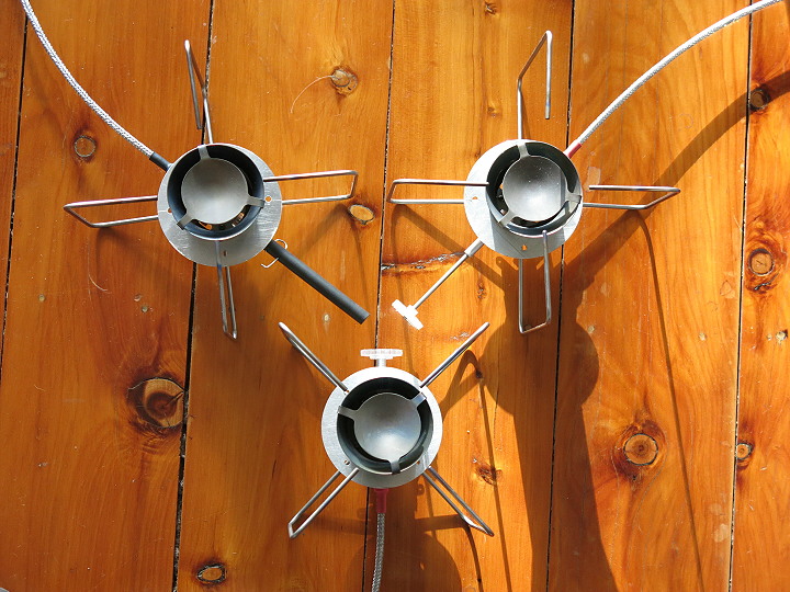
Three different handles for the stove
OK, without the gibberish, that means I like having an nice handle on the stove, and the burnt hairs on my fingers were a surprise. So I ended up with three alternatives: a fat CF tube handle, a thin Ti wire handle with a plastic knob at the end, and a short handle with the same plastic knob at the end. I have a few of the Ti wire version, but I prefer the CF tube for myself.
What it takes
With all these different ideas being tested, you might wonder about the ‘scrap rate’. I think the machining time used in making all the variations used for testing is probably far more significant, but indeed some scrap was generated. But only a few dollar’s worth really.
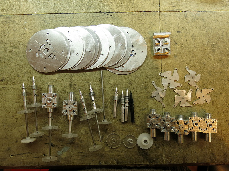
Left overs and rejects
You might recognise some of the bits. Some of them were almost usable, but their replacements were even better. I don’t like trying to use what I consider to be ‘sub-standard’ parts. I usually have to make 2 or 3 units to check out the CNC program anyhow. I wonder what my ‘scrap rate’ is like compared with NASA?
Efficiency, Boil time and CO
After all the performance testing I did for my Carbon Monoxide series
I have ceased to worry about these: they are meaningless for good canister stoves. To explain: provided the flame does not hit a cold object before combustion is mostly complete, the flame will not be quenched and combustion will complete. CO emission will be under 10 ppm, which is fine. And of course, the real heating power comes from the hot gases after the flame has burnt; it does not come from interfering with the flame while it is burning. Translation for commercial stoves: many of them have the pot too close to the burner, so the flame gets quenched. Why they are designed like that is anyone’s guess – maybe they were trying to avoid the need for a windshield? Stupid idea. That did come out very clearly in our series on CO emissions.
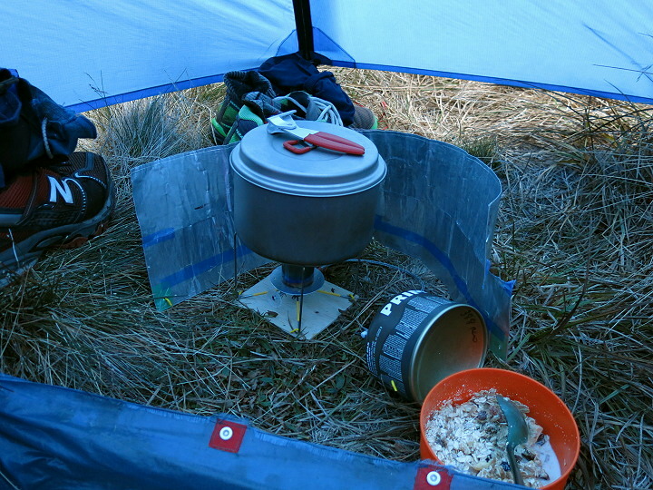
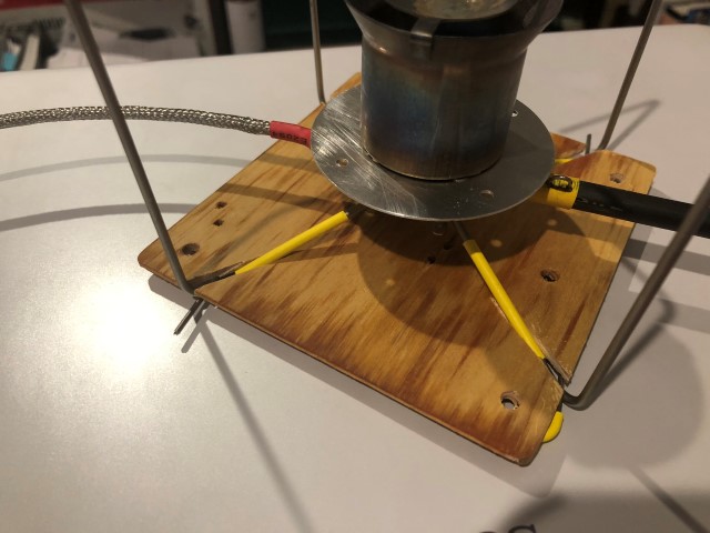
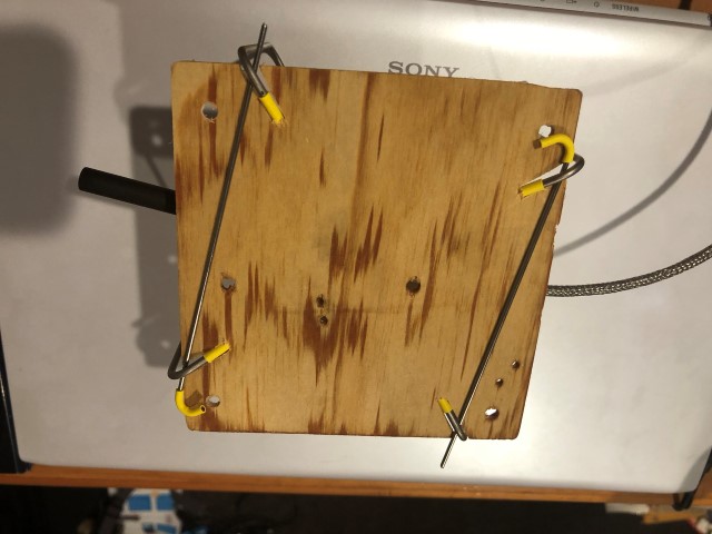
Breakfast, Australian Alps, about 1,500 m, about -7 C outside, warm milk for muesli
If combustion is complete then the efficiency of heating is not really set by the (canister) stove but by the use of a windscreen, the diameter of the pot, the use of a lid on the pot and how far up the sides of the pot the flames go. If the flames are visible up the sides then you are wasting fuel and should turn the stove down a bit. If you don’t have a decent windscreen to the windward and 3/4 of the way around the pot, the hot air will be blown away before it can heat the pot. (I opened the windscreen up a bit here for the photo.) If you have a tiny narrow beercan pot you probably cannot avoid having the flames go up the sides, but a larger pot with an adequate diameter will be far more efficient in heat transfer. If you don’t have a lid on the pot the loss of heat due to evaporation (steam) will be huge. You should see how fast an open pot of hot water can turn into ice late in the evening in the snow!
Some fine details about the actual field configuration shown above. All 4 stove legs have been pinned down through the little 3-ply base board with 1.6 mm Ti wire micro-stakes. The windscreen has also been pinned down with the same micro-stakes (1.05 g each). I love the stability. Both the stove legs and the micro-stakes have short lengths of yellow heatshrink on them so I can find them in the snow grass after I drop them. Trust me: the yellow is both necessary and it works. (Translation: the yellow bits were the only reason I found the dropped micro-stakes one evening – in the snow grass in the vestibule.) Normally I face the concave bottom of the canister to the flames to warm the fuel in the canister as well, although the acetal plastic in the canister connector can take the heat.
Water boiling, showing flame spread, in a Ti pot
I am not interested in ‘peak power’ or in minimum boil time. To be sure, you can put a bigger jet in the stove, have flames everywhere and reduce the boil time, but you will also be killing the efficiency. I am not interested in that. Actually, the shape of the flame spread is more important for any cooking: a highly focused spot (like from the MSR Pocket Rocket) will burn your food much faster than anything else. As the photo here shows, you get a good flame spread even with a Ti pot.
Heat exchanger pots will increase the efficiency a bit, because the fins tend to suck energy out of the flames. However, if the pot is too close to the burner this will quench the flames and create lots of CO, and HX pots are much heavier. Your call.
Is There More to Come?
Yes, there is. Part 4 is a post-construction analysis: how well does the design work, or possibly how ‘does it work’? Multi-channel data logging and graphs. It also covers a whole lot of ‘minor’ performance details at the end, which details actually can be quite significant in the field.