Introduction
I had a small hiccup in the development of the SUL Remote Inverted Canister Winter Stove V7. In brief, at peak power with a cold liquid feed, the vaporisation process inside the Stove Body could fail and the stove could flare, with tall wobbly flames. Shutting off the fuel at the canister when this happens clearly shows blobs of liquid fuel coming through the jet as the stove dies. This is not good enough – it’s not even safe. Much research was done to find out what was going wrong. In hindsight, the problem was fairly simple but had some interesting twists.
What is ‘peak power’? It’s what one gets when the needle valve is opened wide with a liquid feed. There is quite a roar. Signs of flame lift-off may happen, and that can be very dangerous. That said, I never run any stove at peak power: it is very wasteful of fuel as half the flames go up the side of the pot and are wasted.
I only run stoves just up to medium power; dinner gets cooked – or coffee brewed, quite quickly. Because of this, I never tested the V7 at peak power, which was my mistake.
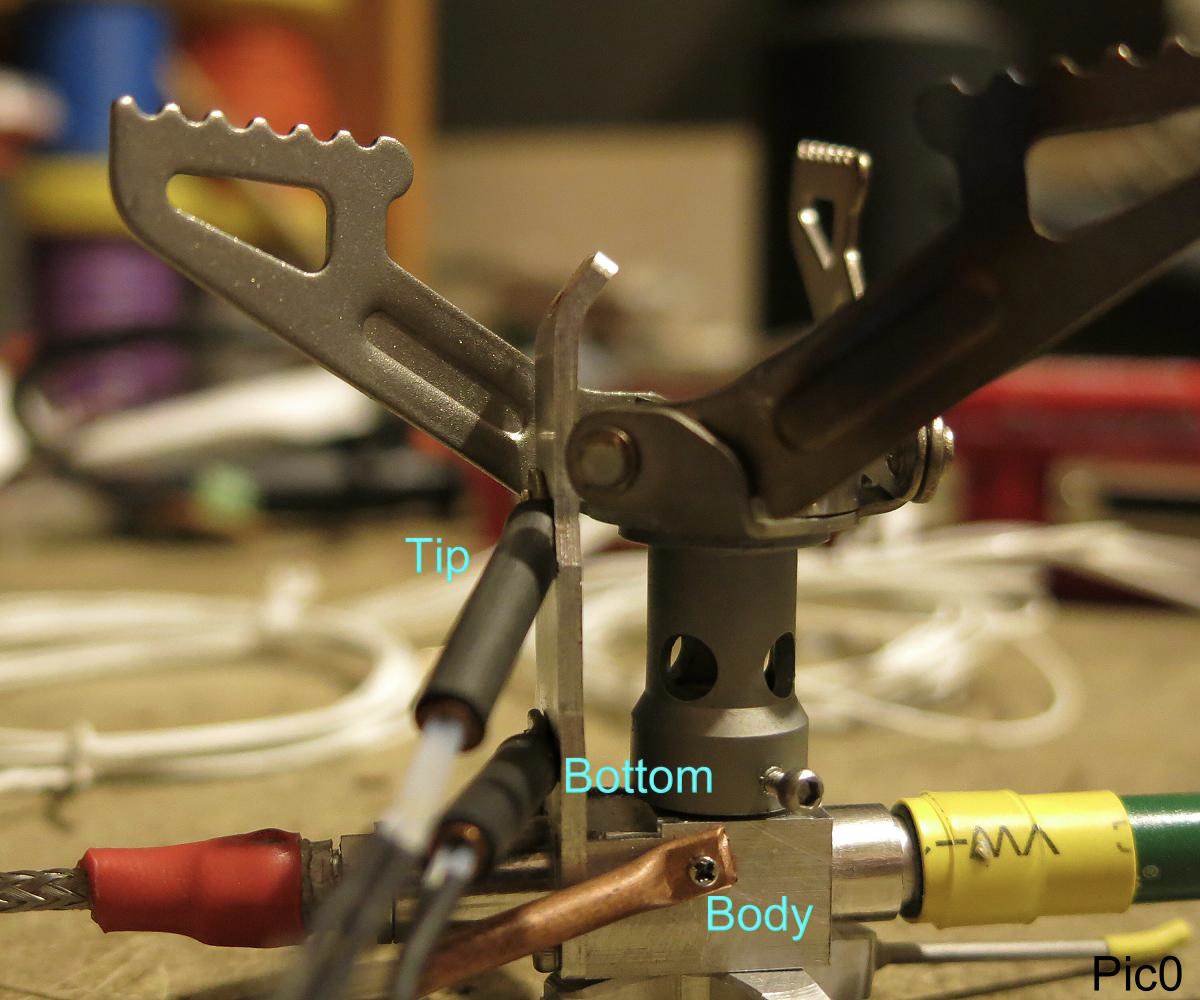
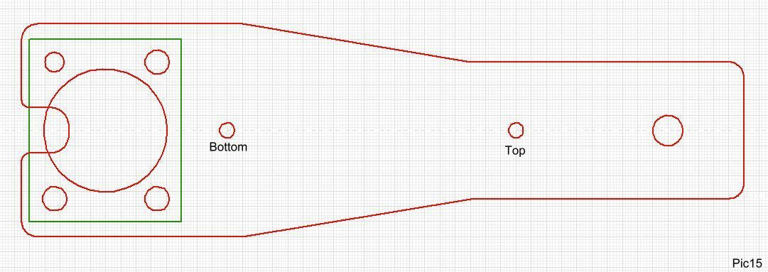
In what follows there will be frequent reference to “Tip”, “Bottom”, “Body”. These are the temperatures as measured near the Tip (top end) of the Heat Shunt (HS), near the Bottom of the HS where it is bolted to the Stove Body, and to the body of the stove itself. They are illustrated above and below. The Heat Exchanger (HX) is a small rod inside the Stove Body which spreads the incoming fuel into a thin film, for vaporisation. Details will follow.
This photo also shows short bits of copper tube attached via M1.2 SS bolts. They hold the temperature-measuring thermistors (in little glass beads) during testing. They also support the leads (they are a little delicate) and they make sure the leads do not cool the glass bead. These copper tubes do not form part of the stove in practice. The locations on the HS are also shown below as the two very small red circles on the central axis.
Later on I made steel clamps to clamp a copper tube to the Stove body, without any bolts. That made testing possible without drilling and tapping holes in either the HS or the Stove Body, which is very convenient.
Please Note: My drawings etc are simplified and not very artistic. Sorry about that.
Member Exclusive
A Premium or Unlimited Membership* is required to view the rest of this article.
* A Basic Membership is required to view Member Q&A events

Home › Forums › MYOG: SUL Remote Inverted Canister Winter Stove Update