Topic
Project: 4oz 1A USB Charger
Forum Posting
A Membership is required to post in the forums. Login or become a member to post in the member forums!
Home › Forums › Gear Forums › Make Your Own Gear › Project: 4oz 1A USB Charger
- This topic is empty.
-
AuthorPosts
-
Sep 19, 2012 at 8:08 am #1913639
Stuart, that's a really good point about the oscillation. I didn't think of that. So I'm not sure how best to reduce that on my boost regulator. e.g. So let's say that it's lower than ideal light and I'm charging my device with my panel, and it's pulling .5A so it's folding back the voltage on the panel. I can put a voltage divider on the enable pin of the regulator, to disable it at any given level, but when the reg shuts off, it'll obviously stop drawing current, and the panel voltage will bounce back up. repeat ad infinitum. I don't think I need the diode since the regulator will shut down. I guess I may simply not care if my phone doesn't complain. The output cap on the regulator may be enough to keep the oscillating output voltage of the reg ever getting high enough to even trigger charge mode, or the iPhone may be smart enough to wait a small amount of time seeing a 'good' charge voltage being charging. Either way, it's def a concern…test needed…come on UPS, I need my parts!
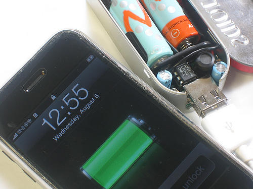
Sep 19, 2012 at 8:14 am #1913643I saw this alternative that I thought was promising for lightweight 'general use'. ($20, you assemble)
http://www.ladyada.net/make/mintyboost/index.html

It uses a buck regulator (step-up) to charge USB devices with 2 AA batteries. A rechargable AA battery can have up to about 2500mAH of charge! But they say this won't quite bring an iPhone up to full power, and will only last two partial charges on two new AA batts.
But then again each AA battery is about 1oz, so I'm guessing this is a 3oz charger, and you only get two partial charges out of it. For another oz. I'll take my infinite number of charges under clear skies :)
Sep 19, 2012 at 8:18 am #1913645"Jack, think I'm into this one for $100 bucks already :) I'm not sure how well they would sell at that price!"
People will pay Big Bucks to save grams. There might be one or two folk eyeing a summer-long hike and planning to take an iPhone.
"But maybe this project will give me some insight into building another one much cheaper."
You'd need to buy the bits wholesale and in quantity to drop prices. Hie thee to Shenzhen city!
"NOW TAKING ORDERS!!! (MUST PAY UP FRONT!!!)"
That's the spirit.
Keep us posted on development.
Sep 19, 2012 at 3:55 pm #1913788>David, "can the iPhone survive 12 or more volts — which is what a solar panel can put out — on its 5V input line?"
I'm not proposing using an 80-watt, 12-volt panel. But rather, an array of cells that puts out somewhat more than 5 volts (open circuit) at something less than 1 amp at 5 volts. The array will have a performance curve in full sun. The batteries will have a very differently shaped charging curve (almost nothing until near 5 volts, then steep as 5 volts is approached. Where those curves (amps versus volts) intersect is where the combined array and battery will charge. Until the battery nears capacity. THEN, yes, bad things could happen if the phone has no protective circuits and is left connected.
It would be akin to filling a gasoline tank with no auto-shut-off on the hose. How much empty tank? Filling rate? Don't leave it unattended for longer than that. Filling the hot tub, refilling propane cylinders, or drinking beer all take a certainly mindfullness so as not to overdo it. The OP seemed to understand circuits well enough to plot those graphs and select an appropriately small array of cells.
Going with cells only, no circuitry; reduces weight AND increases efficiency. It does place the burden of oversight on the user. You definitely couldn't "set it and forget it".
Sep 19, 2012 at 5:09 pm #1913825Touché on the beers David. It's easy to know when you've had enough…you run out of beer! Seriously good points!!
Sep 21, 2012 at 9:59 am #1914376How were you planning on waterproofing your electronics? Not having any other practical solution in my head, I've built mine into a heavy Otterbox:
http://www.backpackinglight.com/cgi-bin/backpackinglight/forums/thread_display.html?forum_thread_id=64564
If you've thought of a lighter solution, I'd love to see it…Also, I don't know if you considered building it with just the WeatherPro panels without the canvas backing; you might save some money and total weight…. I haven't posted my update to the thread above, but the bare panels held up fine on an overnighter a few weeks ago.
Sep 21, 2012 at 10:18 am #1914379As a continuation to the comments about battery chargers, I strongly recommend these:
New Trent iTorch 5200 mAh $33
http://www.amazon.com/New-Trent-IMP52D-Thunderbolt-Blackberry/dp/B0013G8PTS/ref=sr_1_4?ie=UTF8&qid=1348246805&sr=8-4&keywords=smartphone+battery+chargerAnker Astro2 8400 mAh $50
http://www.amazon.com/Upgraded-Version-External-Flashlight-Smartphones/dp/B0067UPRQ4/ref=sr_1_6?ie=UTF8&qid=1348246805&sr=8-6&keywords=smartphone+battery+chargerThese are both brands that have been in the business for at least a few years, and seem very high quality to me. Plus they have LED flashlights (the iTorch even has a laser) built-in!
My wife keeps the iTorch, but the Astro2 that I keep on me is 187 g, 6.6 oz… a bit heavy but enough to charge a smartphone several times over… I use it for travel
Sep 24, 2012 at 8:24 am #1915127Matt,
The Panels actually are the weather proof already, so I'm good there! Which is why I went with the canvas backed type instead of the individual bare panels. This was MUCH cheaper that buying them individually.
So I have a couple of issues with weatherproofing my controller electronics. First, obviously the open USB port can't be waterproofed. It has to be open to the world to accept the USB cable/Ipod cord. Second, there is a small amount generated by the inefficiencies inherent in the design and I don't want to insulate it too much so that is overheats. I'm requiring one amp from this guy, so I will be generating a bit of junction heat! The circuit does have a thermal shutoff, but that kind off defeats the purpose! Especially because I'll be setting this in the hot sun. So I'm looking at two options. The easiest, is plasti-dip spray. It's easy to apply, won't damage anything and can be scraped of easily enough to make changes. Of course that offers no mechanical protection. My other option is a small cover which I'd sew directly to the fabric on back of the 'last' panel. I'd use something akin to half of a square dental floss case. This would provide the mechanical protection and could be combined with the plastidip spray or even some liquidtape brush on if the heat buildup turns out not to be an issue! That being said, it's only a one sided board, so I'd only need to seal one side, which helps considerably for heat.
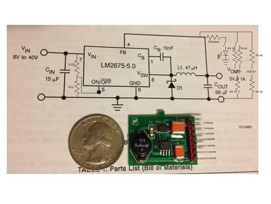
Sep 24, 2012 at 8:31 am #1915131So here's a pic of the actual board and a sketch of the modifications I plan to make to it. The LED is switched, and therefore can be a brighter 8mA light. The USB D- contact can also be switched from .5mA to 1A charging mode. Note that this charger will be mainly for Apple Devices since Apple requires the strange data voltages, so I may wire straight into the iPhone cable to further minimize weight and separable parts. I may also put a mini connector on the solar panel wires to the board, so I can swap this out for a 12V or other charge controller on the fly. I intend to use surface mount parts glued to the very small 'spare areas' of the board accessing the traces as needed. And I have no idea where to put the switches, which may have to go on the inside of the cover!
 Sep 24, 2012 at 4:06 pm #1915242
> The voltage out of a solar panel (before the regulator) will decrease as more current is pulled.
Correct. But I don't think many people really understand what happens with a solar panel. All the discussion has been about volts and amps, but that is the wrong way to look at the whole system. Let me explain.
What really matters with a solar panel is the incoming POWER from the sun. The solar panel can only deliver as much power as it gets (allowing for inefficiencies of conversion). What the output voltage is does not really matter, nor is it fixed. The panel voltage will adapt to the situation.
This means that you can stick a solar panel rated at 12 V onto a 7 V battery and it will happily deliver power to the battery at around 7 V and charge it up. Of course, if you try to use a 3 V solar cell you won't get very far. If you try to use a 100 V solar cell, bad things might happen as well.
The next thing to consider is how the rechargable Lithium battery behaves. Most rechargable Lithium batteries have internal circuitry to limit the input voltage. Very often that circuit also limits output current in the event of a short circuit. That is a safety feature they are required to have, to prevent fires. When the battery is fully charged the internal cell voltage rises of course; at some point the little safety circuit inside says 'enough' and shuts off. It won't accept any more charge. At that point the apparent external terminal voltage can rise several volts.
So my solar charging system sticks the output of the 12 V solar cell straight onto the 7.2 V recharable lithium battery, and charges it. When the battery is fully charged the safety circuit switches off and the battery stops taking charge. Ah, but that means the solar cell is no longer delivering power, so its terminal voltage rises up towards 13 V. Yes, the safety circuit in Lithium battery can handle that. The high voltage is then enough to push current through a series combination of white LED (3.6 V) plus 10 V zener diode. So when I see the white LED shining I know the battery is fully charged, and I can take it out.
Yes, this does mean that I recharge the 7.2 V lithium battery OUT of whatever it goes in. It may well be that the phone/whatever cannot take 13 V on the input. That's OK, I don't stress it. I carry two small lithium batteries and recharge one externally while the other one drives the phone/whatever.
Of course, this also works on a PAIR of 3 V rechargables for a UV Steripen. Been recharging them that way for years.
Cheers
Sep 24, 2012 at 5:09 pm #1915271Of course, here we are talking about charging an iPhone which does not have removable batteries and we don't know how much voltage it can take at its USB input charge line without breaking. The designers don't have much reason to design for voltages higher than the USB standard of 5.25V. Alas, Apple doesn't give out any useful specs for things like maximum input voltage.
Sep 24, 2012 at 6:24 pm #1915289Wow, that's a pretty clean looking board, you have some serious skills. I don't envy one who needs to glue surface mount components to the spare areas and "access traces as needed"!
If it was me, I'd just access the pin outs on the side (assuming that is what's going on). Do you have a bench to validate functionality, or will you just field test it cold turkey? Fun project indeed!
Sep 24, 2012 at 6:29 pm #1915291> an iPhone which does not have removable batteries
Oh well, defective design.
And now you have Apple maps…Cheers
Sep 24, 2012 at 6:38 pm #1915294"[…] an iPhone which does not have removable batteries […]"
"Oh well, defective design.
And now you have Apple maps…"Oh, it gets better: the CDMA (non-GSM) version used by Verizon, a major carrier in the US, does not permit shutting off the phone's radio without also shutting off the GPS receiver. So if you're in the backcountry, away from any cell towers, the phone goes into high power "search" mode, rapidly draining the battery. Unless you put it into Airplane Mode, which then kills the GPS receiver.
Why? It is a mystery.
(Not trying to create thread drift here, just sayin')
Sep 24, 2012 at 7:11 pm #1915304Why is it that, despite being highly opinionated and blunt, Roger and I don't get into arguments? I suspect we're "reading from the same book(s)" and they are mostly engineering references.
Roger: I agree with your logic and practice of using a 12-volt array to charge a 7.2 volt lithium battery. BUT, I think you could save weight with little loss of charging rate if you had a 9-10 volt array. Alas, that's not an off-the-shelf item, but if you wire individual solar cells in series, than you can choose a lower max voltage, save weight, and gain a bit of efficiency.
Question: Do even AA lithium batteries have the internal circuits you describe? Disposables and/or rechargeables?
Anecdote: I had a ChemEng friend from high school Math Club days who went to work at a lithium battery company back in the early days. The fastest way to empty a room was to yell "hot cell" and then everyone would belly-crawl out to the fire escapes. These were auto-battery-sized lithiums and held A LOT of energy. Their joke, since they were going into cruise missles, was, if it doesn't work, it blows up. If it works, it blows up.
Sep 25, 2012 at 10:57 am #1915438"Question: Do even AA lithium batteries have the internal circuits you describe? Disposables and/or rechargeables?"
Two different chemistries.
AA and similar disposable nonrechargable lithium batteries use lithium iron disulphide chemistry, and are not the same as the rechargeable lithium-ion technology used in cell phones.
There are no rechargeable AA Li-ion batteries on the market for a few reasons, one being that Li-ion tech gives 4.20V/cell which would kind of smoke your usual flashlight or digital camera, and because without careful charging, Li-ion batteries can overpressure and create messy and embarrassing explosions.
Sep 25, 2012 at 2:19 pm #1915504Hi David
Ah, but which of us is the ' highly opinionated and blunt' person?
Probably me.
OK, definitely me :-)> if you wire individual solar cells in series [to get a 9-10 V array]
Oh, true. It would work well.
But my gut feel is that the result might be more rather expensive, since you would have to buy a number of them. The 12 V units are really mass-produced, packaged and distributed.Would you get better results/performance? I am not sure about that. The limiting factor with solar cells is always the area of the cells (and the angle of incidence).OK, and the intrinsic efficiency of the cell. Hum … interesting question. Dunno.
Would it make all that much difference? Doubtful imho, but I might be wrong.> Do even AA lithium batteries have the internal circuits you describe? Disposables and/or rechargeables?
My understanding (I could be wrong) is that the 1.5 V AA primaries (Energiser brand) do have that internal circuit.
Don't think I have seen rechargable AA batteries yet. Not sure the chemistry which gives 1.5 V can be recharged.Are there other brands offering rechargable 1.5 V yet? If I am missing something here I am sure someone will help out.
Cheers
PS: rechargable 3 V and 3.6 V, yes, they are available. But we are talking about 1.5 V here.Sep 26, 2012 at 12:09 pm #1915802So the breadboard was a success in that it gladly accepted 12V and output 5V! I haven't hooked it up to my iPhone quite yet to do any time tests or mode tests. The LED circuit is a no brainer and really nice to see what's going on (no switch in the breadboard, it's just constantly connected and shows when the 5V is coming out). I changed the shutoff circuitry values slightly (I'll post an updated schematic later) to accommodate variation chip to chip better, so that circuit pulls .4mA so it's only a SLIGHT drain.

I also took apart a 30 dollar iPhone specific USB Car Charger from Griffin. I've had it for a while, and I thought it would be fun to do a comparison as it's pretty good quality. It's a 500mA unit so I did my measurements apples to apples with just the 10ohm load, although both circuits do function under the 5ohm load.
So here's how the fight went…
In the red corner, hailing from China, Griffin with an input of 11.93V pulled .287A to generate 5.1V out at .467A. That is a 3.424W use of power to generate 2.382W or a paltry 69.56% efficiency.And in the blue corner representing the USA, the brainchild of National, Texas Instruments, and the Wiz, the FUCD (Four ounce Usb Charging Device, I crack myself up) at the same 11.93V pulling only .217A, put up 5V at .455A. USA is the clear winner with a 2.589W use of power for a 2.275W output, yielding 87.9% efficiency!!! Just shy of the hoped for 90%, but I'll take it. Technically the LED and shutoff circuit are taking 50mW of power (most of that is the LED), so with the switch that was so wisely suggested, I'd be at about 89.8%.
More to come. Next, the iPhone test, then I'll finally let the sun do the powering and see if it can push a full 1A!!! Let me know if you have any additional optimization ideas!
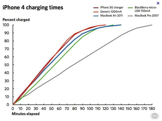
Sep 26, 2012 at 12:45 pm #1915821At a few points during this fun, I thought about limiting the system to just the 500mA setting for simplicity sake. But I found this graph, that basically says it really will charge almost twice as fast at 1A and if I can get that much juice from the panel, that's worth while.

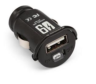
And since I destroyed my Griffin Charger, well the case anyway. I might go ahead and pick up one of these as maybe even use it as a test subject! http://www.thinkgeek.com/product/eea9/?srp=3
 Sep 26, 2012 at 9:30 pm #1916015
Oz, fantastic! I'll probably copy your work sometime, although I don't have the intestinal fortitude to surface mount the mods on the eval board. Two questions, the specs are a bit picky on coupling to the inductor, which should not be a problem if I take the mods off board. Do you not see that as a problem? That's probably much ado … What is the 2V rail for? I know nothing about charging smart-phones.
Thanks for documenting your progress.
Sep 27, 2012 at 6:14 am #1916060David, so the inductor pretty much takes up one end of the board, and the spec sheet details some of the proper component placement and routing on a PCB to help with noise. I'll put the mods on the other end of the board (or maybe on the backside beneath a ground plane) to reduce the probability of issues, but I really don't think it'll matter in full sun. My only real concern is the shutoff pin, and I may add a diode and capcitor to give just a bit of hysterisis to minimize (though it won't eliminate) oscillation in low light conditions.
I talked a bit about the 2V/2.5V rail on the USB Data lines in my original post, but basically they are an iPhone specific requirement to ensure that the charger is 'proper' and also it tells the iPhone which charging mode to use. The iPhone won't necessarily charge without it, you'll get a "not a compatible charging device" message if you don't add the Data Line voltages. In addition, the level of those voltages changes the internal charge controller in the phone and allows it to charge in 2 different modes depending on the capacity of your charger.
I still need to check if I need or want an additional diode if the phone discharges when the solar panel output too low of a voltage and shuts the IC off. So more to come!
Sep 27, 2012 at 8:10 am #1916097Rather than a $15+shipping, one-port charger from Thinkgeek, how about a $1.50+free shipping, two-port car charger off ebay? Or a 1.0A + 2.1A dual-port charger for $3.60+free shipping:
They're all made in China, right? Might as cut out the middleman (middlemonkey?) and have it shipped direct. That's been my approach for years now on camera batteries, chargers, etc.
Sep 27, 2012 at 8:26 am #1916103Roger: I was observing that neither of us holds back in technical realms.
Agreed on the mass-produced aspect of 12-volt PV panels.
http://www.lettingchiboboshine.org.au/pages/activities/investigating-the-characteristics-of-photovoltaic-solar-panels.php has this chart:

Here's a link to another chart:
http://www.flickr.com/photos/mitopencourseware/3323453932/
with a less flat curve as you approach short-circuit current, but again, max power is at 18 volts and near-max power is in the 15-19 volt range. Instead of 36 cells in series, 12 cells in series would give max power at 5.5 volts and a max voltage of 7 volts. Such a panel producing 1 amp or less could be hooked directly to a phone for charging (give or take that 2-volt, iPhone-specific signal WofOZ speaks of).
Ideally one would rewire a 3-row, "12-volt" array of 0.3 amps into a 5-volt, 0.9 amp array by changing the rows of cells from being in series to being in parallel while utilizing as much of the mass-produced packaging as possible.
Sep 27, 2012 at 9:09 am #1916115This just might be my favorite MYOG thread I've seen yet.
Some of this still goes over my head (realizing I remember less of my electronics course from years ago than I thought) but it's definitely encouraging me to give something like this a try. I don't think it would take long to refresh my memory of this stuff.
Sep 27, 2012 at 10:52 am #1916140Yea, not so much on the ebay one…I see your point, but if you take a few apart, the knockoffs (from china, or wherever) are generally assembled poorly with very bad quality control. If they don't have oversight of a good company, they buy the cheapest parts possible (which may be seconds or fakes), and monkey's often put them together. You can get great leftovers and surplus on ebay and for some electronics you can even do the knockoffs, but $15 bucks for a quality part designed by thinkgeek is well worth it to me.
An aptly timed comment though :)
-
AuthorPosts


- You must be logged in to reply to this topic.
Forum Posting
A Membership is required to post in the forums. Login or become a member to post in the member forums!
Our Community Posts are Moderated
Backpacking Light community posts are moderated and here to foster helpful and positive discussions about lightweight backpacking. Please be mindful of our values and boundaries and review our Community Guidelines prior to posting.
Get the Newsletter
Gear Research & Discovery Tools
- Browse our curated Gear Shop
- See the latest Gear Deals and Sales
- Our Recommendations
- Search for Gear on Sale with the Gear Finder
- Used Gear Swap
- Member Gear Reviews and BPL Gear Review Articles
- Browse by Gear Type or Brand.
